DDS Synthesizer on Verilog
In this post, I will share with you how I dealt with writing a DDS synthesizer on Verilog. It will be used to generate a sinusoidal oscillation, the frequency and the initial phase of which can be adjusted and calculated for use with an 8-bit unipolar DAC. How the synthesizer works is well written in the article of the journal Components and Technologies . Symmetry is used to reduce the used memory of the sine table.
For compiling under Linux, I used Iverilog, and for displaying GTKWave. For convenience, a simple Makefile was written, maybe someone will need it. Initially, using the iverilog compiler, we get the tb.out file, and then send it to the vvp simulator, which is installed along with iverilog. As a result, vvp will generate out.vcd, which contains all the variables (signals) used in the project. The display target, in addition to the above, will launch GTKWave with a file of variables and you can see the time diagrams of the signals.
SRC = nco.v TB = nco_tb.v all: iverilog -o tb.out $(TB) vvp -lxt tb.out check: iverilog -v $(TB) display: iverilog -o tb.out $(TB) vvp -lxt tb.out gtkwave out.vcd & clean: rm -rf *.out *.vcd *.vvp First of all, it is necessary to place in the memory a table of the future sine, for I wrote a simple Python script that breaks a quarter of the sine period into 64 points and generates it in a format that you can then copy into the source code. Since I conceived the DDS implementation for an external unipolar DAC with a bit width not exceeding 8 bits, the sine amplitude should be in the range from 0 to 256, where in the range 0 ... 127 lies a negative half-period, and in 128 ... 255 - a positive . In this regard, the obtained sine values (from 0 to pi / 4) are multiplied by 127, and then 127 are added to them. As a result, the values of the first quarter of the period are obtained, the amplitude of which is 128 ... 256.
Pay attention to the fact that with such a formation, the sine at the output of the DAC will have a constant component. In order to remove it, you must pass it through a capacitor.
import numpy as np x=np.linspace(0,np.pi/2,64) print(np.sin(x)) y=127*np.sin(x) print(len(y)) print(y) z=[] i = 0 for elem in y: if int(elem)<=16: print("lut[%d] = 7'h0%X;" % (i, int(elem))) else: print("lut[%d] = 7'h%X;" % (i, int(elem))) z.append(hex(int(elem))) i = i + 1 Since the sine function is symmetric (odd), then you can detect the first symmetry sin (x) = - sin (pi + x). The second symmetry is characterized by the fact that having a table for a quarter of a period, the second quarter can be obtained by passing the table in reverse order (since the sine on the half-period first increases, then decreases).
We form a sine
The main part of the DDS synthesizer is the phase battery. In essence, it is an element index from the Look Up Table (LUT). For each period of the clock signal, the value in it increases by a certain value, as a result, the output is a sine. The frequency of the output signal will depend on the increment value of the battery phase - the larger it is, the higher the frequency. However, according to the Kotelnikov criterion, the sampling frequency should be at least 2 times the signal frequency (to avoid the effect of spectrum overlap), hence the limitation on the maximum increment is half the phase accumulator. In general, the engineering criterion is the sampling frequency = 2.2 signal frequencies, therefore, having decided not to take it to the extreme, I removed another bit, leaving 6 bits per increment when the phase accumulator is 8 bits (although this is already the sinus of the shakalit).
Because of the symmetry used, only the lower 6 bits 2 ^ 6 = 64 will be used directly for the sample by index. The upper 2 bits are used to detect a quarter period of sine generation and, accordingly, a change in the direction of walking around the table. You should have something like this:
module nco(clk, rst, out ); input clk, rst; output reg [7:0] out; reg [5:0] phase_inc = 6'h1; reg [7:0] phase_acc = 0; parameter LUT_SIZE = 64; reg [6:0] lut [0:LUT_SIZE-1]; always @(posedge clk) begin if (rst) begin phase_inc = 6'h1; phase_acc = 0; out = 0; lut[0] = 7'h00; // lut[63] = 7'h7F; end else begin // 1 if (phase_acc[7:6] == 2'b00) begin // LUT out = {1'b1,lut[phase_acc[5:0]]}; end if (phase_acc[7:6] == 2'b01) begin out = {1'b1,lut[~phase_acc[5:0]]}; end if (phase_acc[7:6] == 2'b10) begin out = {1'b0,~lut[phase_acc[5:0]]}; end if (phase_acc[7:6] == 2'b11) begin out = {1'b0,~lut[~phase_acc[5:0]]}; end phase_acc = phase_acc + {2'b0,phase_inc}; end end endmodule When reset, we initialize everything with zeros, except for the value of the phase increment, it is set to one. To save the synthesizability of the code, we will fill the table with values also during the reset. In a real project, it is desirable to use the block memory built into the FPGA for such purposes and create a separate configuration file for it, and use the IP core in the project itself.
A bit of explanation about how symmetry works. At each cycle, it is checked (by the 2 high bits) in which quarter the phase accumulator is currently located. If senior = 00, then at the output in the high bit 1 (responsible for the positive half-wave), in the younger ones it is the value from the LUT in accordance with the index. After the value of the phase accumulator exceeds 63 (the first quarter will pass), 01 will appear in the high-order bits, and the low-order bits will be filled again with zeros.
To pass the LUT in reverse order, it is enough to invert the low bits of the phase accumulator (it will continue to increase in each clock cycle, and its inverted value will decrease).
To form a negative half-wave, we write 0 to the high-order bit of the output. And now the value from the sine table itself needs to be inverted. Here the point is that it is necessary to get a mirror copy of a quarter of the sine, and if this is not done, you will get the same pattern as in the first quarter, but lowered down 127. You can check this by removing the inversion in the code.
Change the frequency and initial phase
As already described above, to change the frequency, it is necessary to change the value of the phase increment. New entries will appear:
input [5:0] freq_res; input [7:0] phase; To change the value of the phase increment, we will simply latch it on each step:
always @(posedge clk) begin if (rst) begin //... end else begin //... phase_inc = freq_res; end end With the initial phase, things are not so simple. You must first write it to the intermediate register, and fill this phase with the battery only if the value of the initial phase at the input does not coincide with that previously memorized. Here there is another important point related to the state of racing. We already have a place where we write to the register phase_acc . It is impossible to record simultaneously in several places, since this will record the data that came first. Therefore, the design will look like this:
reg change_phase = 0; // // ( ) // : prev_phase <= phase; if (phase != prev_phase) begin // change_phase <= 1'b1; end if (change_phase) begin // phase_acc <= prev_phase; change_phase <= 1'b0; end else begin // phase_acc = phase_acc + {2'b0,phase_inc}; end Testbench
The testbench code for Iverilog and GTKWave has some designs (with a dollar sign) that are not used in the usual ISE Design Suite or Quartus. Their meaning is to select the monitored signals and download them to a file, then to transfer to the simulator. The testbench work itself is trivial - we do a reset, set the frequency / initial phase and wait some time.
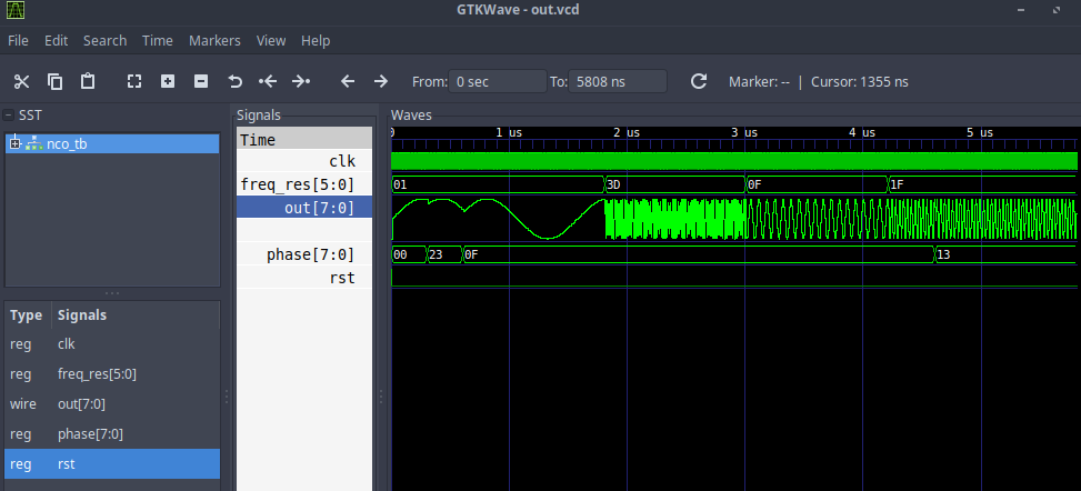
`include "nco.v" `timescale 1ns / 1ps module nco_tb; reg clk = 0, rst = 0; reg [7:0] phase = 0; reg [5:0] freq_res; wire [7:0] out; nco nco_inst ( .clk(clk), .rst(rst), .phase(phase), .freq_res(freq_res), .out(out) ); always #2 clk <= ~clk; initial begin $dumpfile("out.vcd"); $dumpvars(0, nco_tb); //$monitor("time =%4d out=%h",$time,out); rst = 1'b1; freq_res = 1; #8 rst = 1'b0; #300 phase = 8'b00100011; #300 phase = 8'b00001111; #1200 freq_res = 6'b111101; #1200 freq_res = 6'b001111; #1200 freq_res = 6'b011111; #400 phase = 8'b00010011; #1200 $finish; end endmodule Timing charts
At the output, we get something similar to a sine with varying frequency and initial phase at the time points set in the testbench. It is worth noting that with increasing frequency the resolution decreases over it (the number of samples per period), respectively, the clock frequency of the synthesizer and the size of its LUT plays a crucial role in reproducing pure sine (the more its form approaches the ideal, the less side components will be in the spectrum of the resulting signal and the already will be the peak at the generated frequency).

Here you can see that the signal with the second frequency has a not so smooth sine as the others. Consider it closer.

It can be seen that this is still a bit like the sine, the result will be even better after such a signal is passed through the anti-aliasing filter (Low Pass Filter).
Project sources are available here .
Sources
')
Source: https://habr.com/ru/post/457634/
All Articles