Generation of multi-phase PWM signal on TMS320F28027
A long time ago in a distant galaxy far I wrote a short article about the specialized Piccolo controller from Texas Instruments, which is designed to control power converters and electric drives. These controllers are very powerful development tools in many tasks and I wanted to write something else about them ... simple and useful.
Recently, I was puzzled to develop a controller for controlling the engine and, accordingly, a topic was formed for the article - today I will talk about the process of forming a three-phase PWM for controlling the engine, as well as explain the advantages of TMS320F28 from other controllers such as STM32F334, STM32G484, XMC4200 and others.
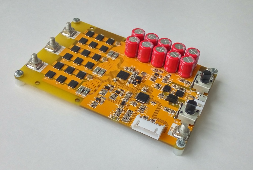
As a stand, I will use the developed controller, alas, I cannot tell in detail about the iron part. True, if I say that the controller is based on the TMS320F28027 + DRV8353RSRGZT bundle, then you can look at the driver datasheet and see the general concept of circuitry + there is debugging on this stone and the reference design is open to it.
In principle, BLDC motors, which “consume” voltage levels, and ordinary three-phase meters, which already want a sinusoidal output, can be controlled on the same type of circuitry. I will show both options, because The path to the sine lies through the formation of voltage levels.
Something about iron
The power part of the driver ideologically consists of 3 half-bridge converters, probably all frequency drives and controllers for controlling BLDC engines in all kinds of copters are similarly executed:
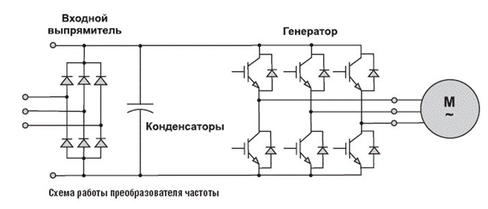
One difference - I do not have an input rectifier, since The original controller is powered by constant voltage. The power source in my case is an assembly from a li-ion battery in the form of 18650 cells. The DRV8353RSRGZT driver used can control just 3 power half-bridges, as well as in the used stone version there are also built-in op amps for working with shunts as current sensors, built-in dc / dc, which is able to digest up to 70 ... 80V and all this is very flexibly adjusted via SPI. For example, it is very convenient to be able to adjust the maximum impulse control current of transistors.
Also in this series there are drivers with a different set of functions, for example, there are with analog control, but not SPI or without built-in dc / dc and without OU. For the price, they are not very different and I took the most "fat" as you probably already understood. The whole thing looks very nice, but I rather lightly approached the design of the driver binding and I got out 2 significant problems. In fact, the problem is one - it is severe overheating:
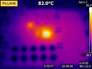
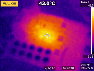
But this problem was caused by 2 reasons. Actually the essence of the problem lies in the overheating of the driver itself. On the thermogram, the driver is loaded with 5A current (for it is almost idle) and nothing warms except the driver and a little bit of the MK itself. Transistors are not even visible, they have the temperature of the printed circuit board, at 5A there is a meager loss of heat.
- Error number 1
My acquaintance pushed me into it, I honestly would have thought at the very least — the dc / dc is built into the driver, which accepts 15 ... 50V at the input and outputs 3.3V to power the MK, logic, comparators and operational amplifiers. It would seem that in my projects there are LM5008 and LM5017 microcircuits in the form of separate microcircuits and I quietly reduced 60V to 3.3V without noticeable heating at a current of 100-150 mA, but everything turned out to be more cunning - the overall efficiency of the converter was about 65-70% at current 300 mA! The fact is that the converter itself can produce 3.3V, but the efficiency will be miserable, the optimal output voltage is 10-12-15V. When the output was 12V 100 mA, my driver stopped warming practically, and the efficiency reached a pleasant 88%. Solution of the problem - with the built-in dc / dc we lower the input 15 ... 50V to 12V, and then from 12V reduce to 3.3V by the external cheap dc / dc.
- Error number 2
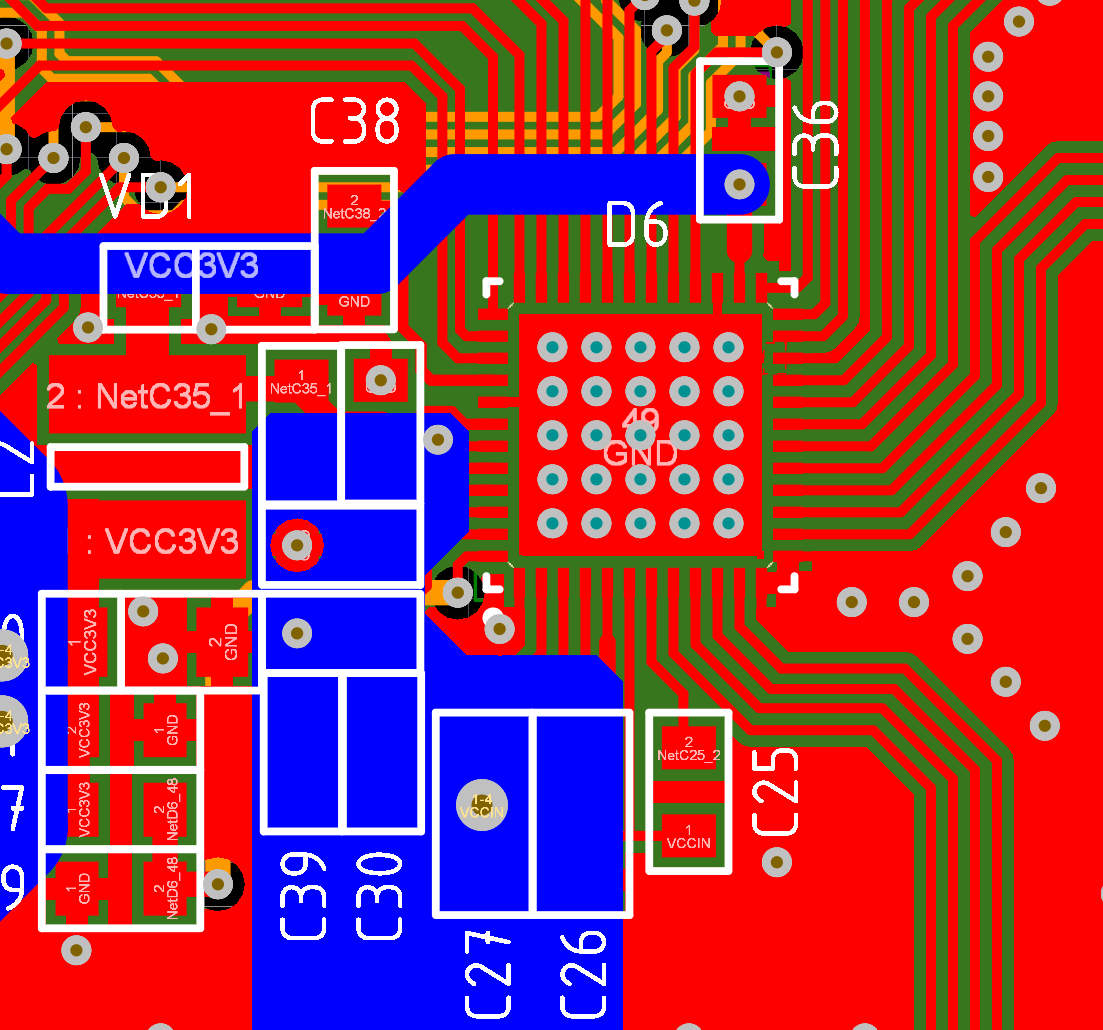
The second mistake is more obvious and the first thing I sinned on her as I could. The fact is that for microcircuits in the QFN package, the main heat removal takes place through the “belly”, it usually sits on GND and through several vias (via) cling to the earthen landfill and all the heat quietly goes there. Initially, I did not take into account the meager efficiency of the built-in dc / dc with a large voltage difference, so I was not embarrassed that the thermocouple (“belly”) clung to the solid GND polygon on the inner layer, on the outer layer I did not have copper under the belly as well GND. As a result, it turned out that ~ 0.5 W of heat is emitted on the chip, and in my case it dissipates into the inner layer of the board, that is, the efficiency is very bad. The solution to the problem is that you also need to make an earthen polygon on the outer layer (Bottom Layer) and not do this:
As a result, these errors were corrected in the second revision of iron: an external dc / dc converter 12-3.3V was added and the GND polygon was added to the lower layer and the chip pad was planted on it + an internal solid polygon was preserved. After such modifications, the temperature in a continuous mode of operation decreased from +82 to +43 o C:
As you can see, by reducing losses, the temperature has dropped significantly under the same conditions, as well as the heat is now more evenly distributed over the board area and does not overheat locally either the driver or the microcontroller. In principle, everything is on the hardware, nothing more interesting happened and it worked steadily. As a result, they can recommend using the DRV8353 driver.
The implementation of the hardware phase shift of 120 o
A feature of the three-phase network is that the current in the phases is not synchronous, but is shifted by 120 o relative to the neighboring one. What is this 120 o phase shift? Speaking in a simple way, this is the offset of the starting point of generation by 1/3 of the period. From the mathematical point of view, the signal period is 2π , which means that the second signal should be moved by 2π / 3, and the third by 4π / 3. From the point of view of electronics, the period is set by the period of reference of our timer. For example, with a clocking of 60 MHz, we want to get a PWM with a frequency of 50 kHz, which means that the timer countdown period will be from 0 to 1200 (60,000,000 Hz / 50,000 Hz = 1200). Now, to get 3 phases with a 120 o shift, we need not touch the 1st phase, add +400 to the current value for the 2nd phase, add +800 to the current value for the 3rd phase.
If we use microcontrollers on the cortex core, then we can implement the shift either by writing a mathematical formula or using event synchronization. It was always surprising to me why ST, NXP and others did not just register where the shift value would be written. Fortunately, TI did this in its TMS320F28xxx, to set the shift, you just need to write one register! To tell why the software solution is not optimal, I will not, just say that it considers the formula MK is not very fast. About the version with synchronization from events is already more adequate and on stm I would do just that, but this option does not allow changing the phase value on the fly, that is, for some phase-shifting bridge again, only the software version remains. Is the advantage of the ability to control the phase of the hardware? This is up to you, my task is to tell you that this is possible. For me, this is an obvious plus when we speak of electric drive control or voltage inverters with a three-phase output.
Now let's configure the generation of PWM signals in the form of 3-complementary pairs with dead time and phase shift. So far without sinus. I will use the following pairs: EPWM1A + EPWM1B, EPWM2A + EPWM2B and EPWM4A + EPWM4B. It is these signals that go from my microcontroller to the driver.
- Step 1
You need to configure the GPIO multiplexer using the GPAMUX register to work with PWM and disable the power supply pull-ups so that at the time of switching on all legs there is no log.1 and the keys are not opened. Protection over current course will save, but it is better not to do so. It is also worth remembering that in order to access the configuration registers, it is necessary to get it with the EALLOW command and then back to enable the overwrite protection with the EDIS command.
void InitGPIOforPWM (void) { EALLOW; GpioCtrlRegs.GPAPUD.bit.GPIO0 = 1; // Disable pull-up on GPIO0 (EPWM1A) GpioCtrlRegs.GPAPUD.bit.GPIO1 = 1; // Disable pull-up on GPIO1 (EPWM1B) GpioCtrlRegs.GPAMUX1.bit.GPIO0 = 1; // Configure GPIO0 as EPWM1A GpioCtrlRegs.GPAMUX1.bit.GPIO1 = 1; // Configure GPIO1 as EPWM1B GpioCtrlRegs.GPAPUD.bit.GPIO2 = 1; // Disable pull-up on GPIO2 (EPWM2A) GpioCtrlRegs.GPAPUD.bit.GPIO3 = 1; // Disable pull-up on GPIO3 (EPWM2B) GpioCtrlRegs.GPAMUX1.bit.GPIO2 = 1; // Configure GPIO2 as EPWM2A GpioCtrlRegs.GPAMUX1.bit.GPIO3 = 1; // Configure GPIO3 as EPWM2B GpioCtrlRegs.GPAPUD.bit.GPIO6 = 1; // Disable pull-up on GPIO6 (EPWM4A) GpioCtrlRegs.GPAPUD.bit.GPIO7 = 1; // Disable pull-up on GPIO7 (EPWM4B) GpioCtrlRegs.GPAMUX1.bit.GPIO6 = 1; // Configure GPIO6 as EPWM4A GpioCtrlRegs.GPAMUX1.bit.GPIO7 = 1; // Configure GPIO7 as EPWM4B EDIS; } - Step 2
We configure the generation of the PWM signal. It is necessary to obtain a frequency of 50 kHz and a phase shift of 120 o . In this case, I use the usual PWM, because this controller has HRPWM, it is important to remember. The PWM module is clocked at the core frequency, that is, 60 MHz, I did not show how to adjust the PLL frequency in the first article on the TMS320, but at the end of the article there will be an archive with the code and you can peek there.
void InitPWM (void) { // EPWM Module 1 config EPwm1Regs.TBPRD = 600; // Set priod EPwm1Regs.TBPHS.half.TBPHS = 0; // Set phase EPwm1Regs.TBCTL.bit.CTRMODE = TB_COUNT_UPDOWN; // Symmetrical mode EPwm1Regs.TBCTL.bit.PHSEN = TB_DISABLE; // Master enable EPwm1Regs.TBCTL.bit.PRDLD = TB_SHADOW; EPwm1Regs.TBCTL.bit.SYNCOSEL = TB_CTR_ZERO; // Sync down-stream module EPwm1Regs.CMPCTL.bit.SHDWAMODE = CC_SHADOW; EPwm1Regs.CMPCTL.bit.SHDWBMODE = CC_SHADOW; EPwm1Regs.CMPCTL.bit.LOADAMODE = CC_CTR_ZERO; EPwm1Regs.CMPCTL.bit.LOADBMODE = CC_CTR_ZERO; EPwm1Regs.AQCTLA.bit.CAU = AQ_SET; EPwm1Regs.AQCTLA.bit.CAD = AQ_CLEAR; EPwm1Regs.DBCTL.bit.OUT_MODE = DB_FULL_ENABLE; // enable dead-time module EPwm1Regs.DBCTL.bit.POLSEL = DB_ACTV_HIC; // Active Hi complementary EPwm1Regs.DBFED = 20; // dead-time on 20 tick EPwm1Regs.DBRED = 20; // dead-time off 20 tick // EPWM Module 2 config EPwm2Regs.TBPRD = 600; EPwm2Regs.TBPHS.half.TBPHS = 400; // Set phase = 400/1200 * 360 = 120 deg EPwm2Regs.TBCTL.bit.CTRMODE = TB_COUNT_UPDOWN; EPwm2Regs.TBCTL.bit.PHSEN = TB_ENABLE; // Slave enable EPwm2Regs.TBCTL.bit.PHSDIR = TB_DOWN; // Count DOWN on sync (=120 deg) EPwm2Regs.TBCTL.bit.PRDLD = TB_SHADOW; EPwm2Regs.TBCTL.bit.SYNCOSEL = TB_SYNC_IN; // sync flow-through EPwm2Regs.CMPCTL.bit.SHDWAMODE = CC_SHADOW; EPwm2Regs.CMPCTL.bit.SHDWBMODE = CC_SHADOW; EPwm2Regs.CMPCTL.bit.LOADAMODE = CC_CTR_ZERO; EPwm2Regs.CMPCTL.bit.LOADBMODE = CC_CTR_ZERO; EPwm2Regs.AQCTLA.bit.CAU = AQ_SET; EPwm2Regs.AQCTLA.bit.CAD = AQ_CLEAR; EPwm2Regs.DBCTL.bit.OUT_MODE = DB_FULL_ENABLE; EPwm2Regs.DBCTL.bit.POLSEL = DB_ACTV_HIC; EPwm2Regs.DBFED = 20; EPwm2Regs.DBRED = 20; // EPWM Module 4 config EPwm4Regs.TBPRD = 600; EPwm4Regs.TBPHS.half.TBPHS = 400; EPwm4Regs.TBCTL.bit.CTRMODE = TB_COUNT_UPDOWN; EPwm4Regs.TBCTL.bit.PHSEN = TB_ENABLE; EPwm4Regs.TBCTL.bit.PHSDIR = TB_UP; EPwm4Regs.TBCTL.bit.PRDLD = TB_SHADOW; EPwm4Regs.TBCTL.bit.SYNCOSEL = TB_SYNC_IN; EPwm4Regs.CMPCTL.bit.SHDWAMODE = CC_SHADOW; EPwm4Regs.CMPCTL.bit.SHDWBMODE = CC_SHADOW; EPwm4Regs.CMPCTL.bit.LOADAMODE = CC_CTR_ZERO; EPwm4Regs.CMPCTL.bit.LOADBMODE = CC_CTR_ZERO; EPwm4Regs.AQCTLA.bit.CAU = AQ_SET; EPwm4Regs.AQCTLA.bit.CAD = AQ_CLEAR; EPwm4Regs.DBCTL.bit.OUT_MODE = DB_FULL_ENABLE; EPwm4Regs.DBCTL.bit.POLSEL = DB_ACTV_HIC; EPwm4Regs.DBFED = 20; EPwm4Regs.DBRED = 20; } Now a little more ... write the period in the TBPRD register, or rather the "period / 2", because we assume the timer in both directions, it turns out that period 600 corresponds to the frequency of the output PWM signal of 50 kHz in the complementary pair mode. In the TBPHS register, we write the phase value to which we need to shift, in this case, 400 out of 600, which corresponds to 2π / 3. It is worth noting that we do not move the 1st phase, so the shift for it is 0, for the 2nd phase, the shift is 400, respectively, but for the 3rd phase, it would seem logical to write 800, but 800 out of 600 somehow not very ... therefore, the shift is written not relative to the 1st phase, but relative to the previous one, that is, the 2nd one. As a result, we find that in the 3rd phase we write 400 and this corresponds to 2π / 3 between phase 2 and 3, and since the 2nd one is already shifted, then between phases 1 and 3 will be "2π / 3 + 2π / 3 = 4π / 3 "and from the point of view of electronics, everything looks logical.
In order for the phases to understand who is moving with respect to whom, a boss is needed, therefore EPWM1 is configured with the PHSEN bit in master mode, and EPWM2 and EPWM4 are respectively slaves (slaves). Also with the help of the SYNCOSEL bits, the synchronization “point” is configured, that is, from where to where to calculate the shift. EPWM1 is synchronized with the start of the timer, that is, with a zero period, and EPWM2 and EPWM4 are already synchronized with respect to the signal edge of the previous channel: the previous channel for EPWM2 is EPWM1, and for EPWM4 it is EPWM2.
Now it remains to turn on the complementary pairs and set the dead-time duration. Using the POLSEL bits, we set a non-inverse PWM, that is, upon reaching the specified value of the comparator (reference), a log is generated at the output. 1. In OUT_MODE set the generation of dead-time and the front and the decline of the signal. Accordingly, in the registers DBFED and DBRED we write the duration of the dead time in cycles.
- Step 3
It now remains to record the value of the duty cycle (duty) in the CMPA register corresponding to each channel and the result can be observed.
EPwm1Regs.CMPA.half.CMPA = 300; // duty for output EPWM1A EPwm2Regs.CMPA.half.CMPA = 300; // duty for output EPWM2A EPwm4Regs.CMPA.half.CMPA = 300; // duty for output EPWM4A 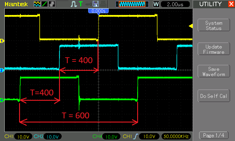
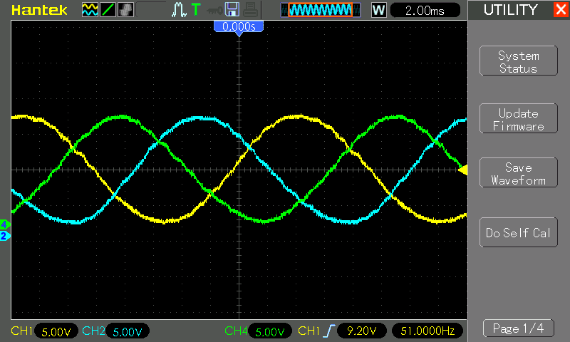
Voila! Oscilloscope probes are connected to the driver output. The yellow channel is our EPWM1, that is, the master. The blue channel is EPWM2 and it is shifted by 2π / 3 (or 400 samples) relative to the yellow channel, and the green channel is shifted by another 400 samples. Thus, we get 3 phases, where each phase is shifted by 120 o .
Now let's transfer the oscilloscope probes from the output of the power bridge to the control signals that come out of the microcontroller and check for the presence of dead-time inside the complementary pair:
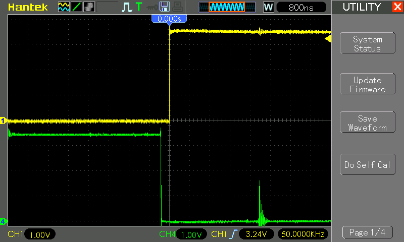
As you can see the dead time set corresponds to the real one. The duration of one sample is 1/60 000 000 Hz = 16.6 ns and we get 20 samples, which is equivalent to the duration of the dead time 20 16.6 ns = 332 ns, * which is approximately observed in the oscillogram.
Actually where this can be useful, in the form that it is now. The most obvious option is multi-phase dc / dc converters, for those interested to google interleaved dc / dc converter . This is an extremely interesting technical solution, which allows to significantly reduce the size of power inductances, reduce the output capacitance of capacitors, as well as increase efficiency. On a simple TMS320F28027 you can implement a 4-phase converter and all this will be very simple implemented in code and only in hardware.
We generate three-phase alternating voltage
In many problems it will not be enough to get discrete values of 0 or VCC at the output, a sine wave is needed. I have an article that tells about the formation of a single-phase AC voltage and uses the “tabular” method, that is, the values for the sine wave are initially calculated. In principle, this can also be done for a three-phase, but I would like to show an alternative option, namely, the calculation of the filling value (duty) in real time or on the fly.
There is one feature. The PWM frequency in this case is also 50 kHz and the phase shift is set between the periods of this signal. Accordingly, when we modulate a 50 Hz sine wave, the hardware phase shift is “lost”, it will still be present between the PWMs, but not inside the sinusoid, so it will have to be done softly. Trigonometry is a heavyweight thing for TMS320F28027, but for me it’s not really loaded, so let it count. If you have a task that requires a large number of calculations, then you need a controller with TMU and FPU, for example, TMS320F280049, which can turn mathematics much faster.
To load the fill values (duty) in PWM, we need a timer, the period of which will set the sampling rate. I need a period of 20 ms (1 / 50Hz = 20 ms) and I take the number of steps in a sinusoid, for example, 20, in the end, with a frequency of 0.02 s / 20 = 0.001 ms = 1 kHz, an interrupt should be generated and in this interrupt I will write the value in the PWM . For simplicity, take the usual timer CPU0 and set it up:
void InitTimer0ForGenerator (void) { EALLOW; PieVectTable.TINT0 = &cpu_timer0_isr; EDIS; InitCpuTimers(); ConfigCpuTimer(&CpuTimer0, 60, 1000); CpuTimer0Regs.TCR.bit.TIE = 1; CpuTimer0Regs.TCR.bit.TSS = 0; IER |= M_INT1; PieCtrlRegs.PIEIER1.bit.INTx7 = 1; // Enable TINT0 in the PIE: Group 1 interrupt 7 EINT; // Enable Global interrupt INTM ERTM; // Enable Global real-time interrupt DBGM } __interrupt void cpu_timer0_isr (void) { CpuTimer0.InterruptCount++; /* * - . ... */ PieCtrlRegs.PIEACK.all = PIEACK_GROUP1; // Acknowledge this interrupt to receive more interrupts from group 1 } The functions InitCpuTimers and ConfigCpuTimer are standard, all settings are in them, we just need to transmit the core frequency (60 MHz) and the counting period in microseconds (1000 μs = 1 ms), which is equivalent to the frequency of 1 kHz, and we had to. So where in the setting function we enable interrupts and pass the address of our interrupt handler, where everything will happen.
Now it is necessary to reinvent the sinus formula, this will require knowledge of school trigonometry and that's it. And so ... we have a function y = sin (x) let's build a graph of this function:
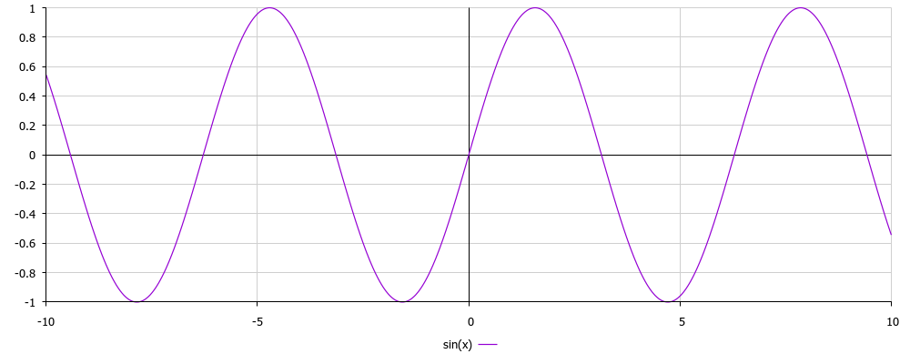
As you can see on the graph, the amplitude of y varies from -1 to 1, we want from 0 to 1, since at the minimum amplitude we have 0V, and at the maximum (equivalent of 1) we have + VCC. To "draw" -1 ... + 1 we need bipolar power, but it is not. It is necessary to shift the graph in a positive direction. If we just raise it up, it will become from 0 to +2, and we can only up to +1. So you need to divide by 2 and that's it! To begin with, let's just divide and plot for y = (sin (x) / 2):
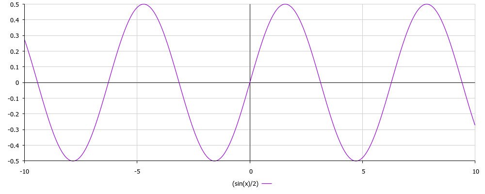
Aha Now the graph has a range from -0.5 to +0.5, that is, the amplitude is 1. Already better, but we have not yet gotten rid of negative values, so let's just shift the graph up by 0.5, for this you just need to add this value to the result and get the formula y = 0.5 + (sin (x) / 2) and plot the graph for this function:

Now everything has become quite beautiful: a sinusoid has an amplitude from 0 to 1, and there are no negative values. The formula y = 0.5 + (sin (x) / 2) describes the 1st phase, now you need to add a phase shift to get phases 2 and 3. To do this, subtract 2π / 3 and 4π / 3 from x, respectively, and we get the formulas for the remaining phases y = 0.5 + (sin (x-2π / 3) / 2) and y = 0.5 + (sin (x-4π / 3) / 2). We build 3 graphics and see if it looks like the truth:
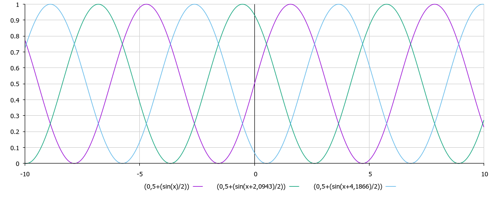
Not bad! The picture is similar to what they usually draw in textbooks of electrical engineering when they talk about a three-phase network or asynchronous motors. By the way, 2.0943 is 2π / 3, and 4.1866, respectively, 4π / 3, I just counted them right away and they figure in my code. Total we have 3 equations:
- Phase A - y = 0.5 + (sin (x) / 2)
- Phase B - y = 0.5 + (sin (x-2π / 3) / 2)
- Phase C - y = 0.5 + (sin (x-4π / 3) / 2)
From the side of mathematics, everything seems to be simple and clear, but now you need to adapt to microcontroller realities. The sinusoid is not analog, but it has “steps”, that is, it is discrete, because we can only set the voltage or 0V or + 15V (VCC) in my case. Earlier, I wrote that I will have 20 steps, which means that for 1 period I will have 20 calculations.
To begin with, we decide what to substitute for x . The period of our sinusoid is 2π , which means that the discretization step will be equal to 2π / 20 . Accordingly, the sinusoid will consist of 20 points, we as if build a graph by points, and approximate between them. As a result, the value in the first step will be sin (2π * (1/20), in the second step sin (2π * (2/20)), in the third step * sin (2π (3/20)) and so on, when we comes to 20/20 , then it will mean the end of the period and we will have to start counting on a new one. Based on the data, let's correct the formulas:
- Phase A - y = 0.5 + (sin (2π * (n / N)) / 2)
- Phase B - y = 0.5 + (sin (2π * (n / N) -2π / 3) / 2)
- Phase C - y = 0.5 + (sin (2π * (n / N) -4π / 3) / 2)
Here, we now consider the value of the sine at each specific point on the graph. Accordingly, n is the current step, N is the total of steps (20). After these formulas, we get a value from 0 to 1, but in reality we operate not with an abstract amplitude. In our case, the amplitude depends on the fill factor, since duty varies from 0 to 600 (from the PWM settings), then 0 is 0, and 1 is equivalent to 600. Based on this, let's recalculate into a real formula to get the value that will be loaded into the CMPA PIM register :
- Phase A - duty1 = A (0.5 + (sin (2π (n / N)) / 2))
- Phase B - duty2 = A (0.5 + (sin (2π (n / N) -2π / 3) / 2))
- Phase C - duty4 = A (0.5 + (sin (2π (n / N) -4π / 3) / 2))
Accordingly, A is the maximum amplitude value, that is, 600, n is the current step, N is the total steps (20). The values of duty1, duty2, duty4 are the recalculated real values of the fill factor (duty) that is loaded into the CMPA. Now let's write the code for the updated interrupt handler and declare all the necessary variables:
float activeStep = 0.0; float amplitude = 600.0; float allStep = 20.0; const float pi = 3.1415; // π const float piTwo = 6.2831; // 2π const float phaseShifted120deg = 2.0943; // 2π/3 const float phaseShifted240deg = 4.1866; // 4π/3 __interrupt void cpu_timer0_isr (void) { if (activeStep >= allStep) {activeStep = 0;} activeStep++; EPwm1Regs.CMPA.half.CMPA = ((uint16_t)(amplitude * (0.5 + (sinf(piTwo * (activeStep / allStep)) / 2)))); EPwm2Regs.CMPA.half.CMPA = ((uint16_t)(amplitude * (0.5 + (sinf(piTwo * (activeStep / allStep) - phaseShifted120deg) / 2)))); EPwm4Regs.CMPA.half.CMPA = ((uint16_t)(amplitude * (0.5 + (sinf(piTwo * (activeStep / allStep) - phaseShifted240deg) / 2)))); PieCtrlRegs.PIEACK.all = PIEACK_GROUP1; // Acknowledge this interrupt to receive more interrupts from group 1 } The code as you can see is the simplest, if you understand what was required to do simple mathematics in the problem to be solved. Each time the interrupt is called, we increment the activeStep variable, which contains the step number, it changes from 0 to 20 and then is reset. It turns out that in one period we perform 20 steps and 20 calculations for each phase. In order not to count in the formula constantly 2π / 3 and 4π / 3, I counted them immediately in order to be used as constants.
Calculations turned out to be a minimum, for this MK it is absolutely nothing. If desired, the number of points can be significantly increased, for example, up to 200. It all depends on the task. The PWM frequency is changed by changing the interrupt call frequency and the number of steps. You can also change the variable amplitude and change the voltage at the output of the power converter.
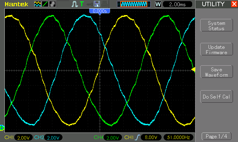
After downloading the code to the microcontroller, you will receive the corresponding picture:
If you stretch the Y curve, it will be better to see the signal defects. This is a consequence of a small number of discretization steps, the conditional rule here applies: the more points, the more beautiful the signal.
Conclusion
Today I talked about the process of forming a phase shift in multiphase systems, in principle there is nothing difficult, especially when using TMS320F28. Then there remains the matter of algorithms, in principle, in the vastness of Runet, there are many articles where the control of brushless motors, asynchronous and all other kinds is chewed, you just have to shift the logic.
I hope this material will be useful and not particularly boring in reading. As always, the source is attached:
')
Source: https://habr.com/ru/post/457548/
All Articles