OpenGL WBOIT: transparency without sorting
It will focus on “Weighted blended order-independent transparency” (hereinafter WBOIT) - the technique described in JCGT in 2013 ( link ).
When several transparent objects appear on the screen, the color of the pixel depends on which one is closer to the observer. Here is the well-known color mixing formula for this case:
The order of the fragments is important for it: the color of the near fragment and its opacity are designated as C near and α , and the resulting color of all fragments that are located behind it - as C far . Opacity is a property that takes values from 0 to 1, where 0 means that the object is so transparent that it is not visible, and 1 means that it is so opaque that nothing is visible behind it .
To use this formula, you must first sort the fragments by depth. Imagine how much a headache is associated with this! In general, sorting should be done in each frame. If you are sorting objects, then some objects of complex shape will have to be cut into pieces and sorted by depth into cut parts (in particular, for intersecting surfaces, this will definitely have to be done). If you are sorting fragments, then the sorting will occur in shaders. This approach is called “Order-independent transparency” (OIT), and it uses a coherent list stored in the video card's memory. Predicting how much memory you have to allocate for this list is almost impossible. And if there is not enough memory, artifacts will appear on the screen.
')
Lucky for those who can control how many translucent objects are placed on the stage, and where they are relative to each other. But if you make a CAD, then you will have as many transparent objects as the user wants, and they will be placed at random.
Now you understand the desire of some people to simplify their lives and come up with a formula for mixing colors that does not require sorting. Such a formula is in the article to which I referred at the beginning. There are even some formulas there, but the best in the opinion of the authors (and in my opinion too) is this one:

In the screenshot - a group of semi-transparent triangles arranged in four layers in depth. On the left, they are rendered using the WBOIT technique. On the right is a picture obtained using formula (1), a classic blending of colors, taking into account the order of the fragments. Further I will call it CODB (Classic order-dependent blending).
Before we start rendering transparent objects, we need to render everything that is not transparent. After that, transparent objects are rendered with a depth test, but without writing to the depth buffer (this is done like this:
C 0 in the formula (2) is the color of the opaque fragment, on top of which transparent fragments are drawn, of which we have n pieces, indicated by indices from 1 to n. C i is the color of the i-th transparent fragment, α i is its opacity.
If you look closely, then formula (2) is a little bit like formula (1). If you imagine that Is C near , C 0 is C far , and
  - this is α , then this will be the 1st formula, one to one. And true - this is the weighted average of the colors of the transparent fragments (the center of mass is determined by the same formula in mechanics), it will go beyond the color of the near fragment C near . C 0 is the color of the opaque fragment located behind all the fragments for which we have calculated this weighted average, and it will pass for C far . That is, we replaced all transparent fragments with one “averaged” fragment and applied the standard color mixing formula - formula (1). What is this clever formula for α that the authors of the original article offer us?
This is a scalar function in n-dimensional space, so recall the differential analysis of functions of several variables. Given that all α i belong to the range from 0 to 1, the partial derivative with respect to any variable will always be a non-negative constant. This means that the opacity of the “averaged” fragment increases as the opacity of any of the transparent fragments increases, and this is exactly what we need. In addition, it increases linearly.
If the opacity of a fragment is 0, then it is not visible at all, it does not affect the resulting color.
If the opacity of at least one fragment is equal to 1, then α is equal to 1. That is, the opaque fragment becomes invisible, which is generally good. Only here the transparent fragments located behind the fragment with opacity = 1 still shine through it and affect the resulting color:

There is an orange triangle on top, green underneath, and gray and cyan beneath the green, all on a black background. In blue, the opacity = 1, all others - 0.5. The picture on the right is what should be. As you can see, WBOIT looks disgusting. The only place where the normal orange color appears is the edge of the green triangle, circled in an opaque white line. As I just said, an opaque fragment is invisible if the opacity of the transparent fragment is 1.
You can see it even better here:

The orange triangle has an opacity of 1, while a green triangle with disabled opacity is simply drawn along with opaque objects. It looks as if the GREEN triangle shines in ORANGE through the orange triangle.
To make the picture look decent, the easiest way is not to assign objects with high opacity. In my working draft, I do not allow setting an opacity greater than 0.5. This is a 3D CAD, in which objects are drawn schematically, and special realism is not required, so that such a restriction is permissible there.
With low opacity values, the left and right images look almost the same:

And with high they differ markedly:

This is what a transparent polyhedron looks like:
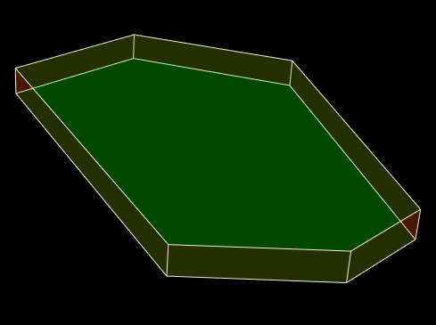
The polyhedron has orange side and green horizontal faces. Unfortunately, at first glance you will not understand it, i.e. The picture does not look convincing. Where the orange wall is in front, you need more orange, and where green is more green. It will be much better to draw edges with one color:
In order to somehow compensate for the lack of sorting by depth, the authors of the article came up with several options for adding depth to formula (2). This makes the implementation more difficult, and the result less predictable and dependent on the features of a particular three-dimensional scene. I did not go into this topic, so whoever is interested - I suggest to read the article.
It is argued that WBOIT is sometimes capable of something that classical transparency with sorting cannot. For example, you draw smoke as a particle system, using only two particles - with dark and light smoke. When one particle passes through another, the classic mixing of colors with sorting gives an ugly result - the color of smoke from light becomes sharply dark. The article says that WBOIT, taking into account the depth, allows you to achieve a smooth transition and looks more likely. The same can be said about the modeling of fur and hair in the form of thin tubes.
Now how to implement the formula (2) on OpenGL. The example code lies on Github ( link ), and most of the pictures in the article come from there. You can collect and play with my triangles. The Qt framework is used.
For those who are just starting to study the rendering of transparent objects, I recommend these two articles:
→ Learn OpenGL. Lesson 4.3 - Mixing colors
→ Order-Independent Transparency algorithm using link lists on Direct3D 11 and OpenGL 4
The second, however, is not so important for understanding this material, but the first is required to read.
To calculate the formula (2), we need 2 additional framebuffers, 3 multisample textures and a render buffer to which we will write the depth. In the first texture - colorTextureNT (NT means non-transparent) - we will render non-transparent objects. It has type GL_RGB16F. The second texture (colorTexture) will be of type GL_RGBA16F; In the first 3 components of this texture, we will write this piece of the formula (2):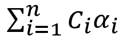 Fourth -
 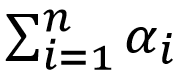 . Another texture of type GL_R16F (alphaTexture) will contain
 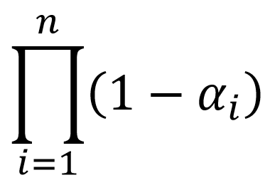 .
.
First you need to create these objects and get their identifiers from OpenGL:
As I said, the Qt framework is used here, and all OpenGL calls go through an object of type QOpenGLFunctions_4_5_Core, which I have denoted everywhere as f.
Now you should allocate memory:
And set up framebuffers:
On the second rendering pass, the output from the fragment shader will go to two textures at once, and this must be explicitly indicated with glDrawBuffers.
Most of this code is executed once, when the program starts. The code that allocates memory for textures and renderbuffers is called each time the window is resized. Next comes the rendering code, which is called every time the window is redrawn.
We have just drawn all the opaque objects on the colorTextureNT texture, and recorded the depths in the renderbuffer. Before you use the same renderbuffer in the next drawing stage, you need to make sure that all the depths of the opaque objects are already written there. For this, GL_FRAMEBUFFER_BARRIER_BIT is used. After rendering the transparent objects, we will call the ApplyTextures () function, which will start the final rendering stage, at which the fragment shader will read data from the colorTextureNT, colorTexture and alphaTexture textures to apply the formula (2). Textures should be fully recorded by that time, so before calling ApplyTextures () we use GL_TEXTURE_FETCH_BARRIER_BIT.
defaultFBO is a framebuffer through which we display an image on the screen. In most cases, this is 0, but in Qt this is QOpenGLWidget :: defaultFramebufferObject ().
Each time we call a fragmentary shader, we will have information about the color and opacity of the current fragment. But at the output in the colorTexture texture we want to get the sum (and in the alphaTexture texture the product) of some functions of these values. For this, blending is used. Moreover, since we calculate the sum for the first texture and the product for the second, the blending settings (glBlendFunc and glBlendEquation) for each attachment must be set separately.
Here is the contents of the PrepareToTransparentRendering () function:
And the contents of the CleanupAfterTransparentRendering () function:
In my fragment shader the opacity is denoted by the letter w. The product of color on w and w itself is displayed in one output parameter, and 1 - w - in another. For each output parameter, the layout qualifier is defined as “location = X”, where X is the index of the element in the array of attachments, which we passed to glDrawBuffers in the 3rd listing (specifically, the output parameter with location = 0 is sent to the texture bound to GL_COLOR_ATTACHMENT0 , and the parameter with location = 1 - to the texture bound to GL_COLOR_ATTACHMENT1). The same numbers are used in the glBlendFunci and glBlendEquationi functions to indicate the attachment number for which we set the blending parameters.
Fragment shader:
In the ApplyTextures () function, we simply draw a rectangle over the entire window. The fragment shader queries the data of all the textures we have created, using the current screen coordinates as texture coordinates and the current sample number (gl_SampleID) as the sample number in the multisample texture. Using the gl_SampleID variable in the shader automatically turns on the mode when the fragment shader is called once for each sample (under normal conditions it is called once for the entire pixel, and the result is written to all samples that were inside the primitive).
There is nothing remarkable about the vertex shader:
Fragment shader:
Finally, the contents of the ApplyTextures () function:
Well, it would be nice to release OpenGL resources after it's over. I have this code called in the destructor of my OpenGL widget:
When several transparent objects appear on the screen, the color of the pixel depends on which one is closer to the observer. Here is the well-known color mixing formula for this case:
The order of the fragments is important for it: the color of the near fragment and its opacity are designated as C near and α , and the resulting color of all fragments that are located behind it - as C far . Opacity is a property that takes values from 0 to 1, where 0 means that the object is so transparent that it is not visible, and 1 means that it is so opaque that nothing is visible behind it .
To use this formula, you must first sort the fragments by depth. Imagine how much a headache is associated with this! In general, sorting should be done in each frame. If you are sorting objects, then some objects of complex shape will have to be cut into pieces and sorted by depth into cut parts (in particular, for intersecting surfaces, this will definitely have to be done). If you are sorting fragments, then the sorting will occur in shaders. This approach is called “Order-independent transparency” (OIT), and it uses a coherent list stored in the video card's memory. Predicting how much memory you have to allocate for this list is almost impossible. And if there is not enough memory, artifacts will appear on the screen.
')
Lucky for those who can control how many translucent objects are placed on the stage, and where they are relative to each other. But if you make a CAD, then you will have as many transparent objects as the user wants, and they will be placed at random.
Now you understand the desire of some people to simplify their lives and come up with a formula for mixing colors that does not require sorting. Such a formula is in the article to which I referred at the beginning. There are even some formulas there, but the best in the opinion of the authors (and in my opinion too) is this one:
In the screenshot - a group of semi-transparent triangles arranged in four layers in depth. On the left, they are rendered using the WBOIT technique. On the right is a picture obtained using formula (1), a classic blending of colors, taking into account the order of the fragments. Further I will call it CODB (Classic order-dependent blending).
Before we start rendering transparent objects, we need to render everything that is not transparent. After that, transparent objects are rendered with a depth test, but without writing to the depth buffer (this is done like this:
glEnable(GL_DEPTH_TEST); glDepthMask(GL_FALSE); ). That is, this is what happens at the point with some screen coordinates (x, y): transparent fragments that are closer to opaque pass the depth test, regardless of how they are located in depth relative to the already drawn transparent fragments, and transparent fragments that are further opaque, do not pass the depth test, and, accordingly, are discarded.C 0 in the formula (2) is the color of the opaque fragment, on top of which transparent fragments are drawn, of which we have n pieces, indicated by indices from 1 to n. C i is the color of the i-th transparent fragment, α i is its opacity.
If you look closely, then formula (2) is a little bit like formula (1). If you imagine that
Is C near , C 0 is C far , and - this is α , then this will be the 1st formula, one to one. And true - this is the weighted average of the colors of the transparent fragments (the center of mass is determined by the same formula in mechanics), it will go beyond the color of the near fragment C near . C 0 is the color of the opaque fragment located behind all the fragments for which we have calculated this weighted average, and it will pass for C far . That is, we replaced all transparent fragments with one “averaged” fragment and applied the standard color mixing formula - formula (1). What is this clever formula for α that the authors of the original article offer us?This is a scalar function in n-dimensional space, so recall the differential analysis of functions of several variables. Given that all α i belong to the range from 0 to 1, the partial derivative with respect to any variable will always be a non-negative constant. This means that the opacity of the “averaged” fragment increases as the opacity of any of the transparent fragments increases, and this is exactly what we need. In addition, it increases linearly.
If the opacity of a fragment is 0, then it is not visible at all, it does not affect the resulting color.
If the opacity of at least one fragment is equal to 1, then α is equal to 1. That is, the opaque fragment becomes invisible, which is generally good. Only here the transparent fragments located behind the fragment with opacity = 1 still shine through it and affect the resulting color:
There is an orange triangle on top, green underneath, and gray and cyan beneath the green, all on a black background. In blue, the opacity = 1, all others - 0.5. The picture on the right is what should be. As you can see, WBOIT looks disgusting. The only place where the normal orange color appears is the edge of the green triangle, circled in an opaque white line. As I just said, an opaque fragment is invisible if the opacity of the transparent fragment is 1.
You can see it even better here:
The orange triangle has an opacity of 1, while a green triangle with disabled opacity is simply drawn along with opaque objects. It looks as if the GREEN triangle shines in ORANGE through the orange triangle.
To make the picture look decent, the easiest way is not to assign objects with high opacity. In my working draft, I do not allow setting an opacity greater than 0.5. This is a 3D CAD, in which objects are drawn schematically, and special realism is not required, so that such a restriction is permissible there.
With low opacity values, the left and right images look almost the same:
And with high they differ markedly:
This is what a transparent polyhedron looks like:
The polyhedron has orange side and green horizontal faces. Unfortunately, at first glance you will not understand it, i.e. The picture does not look convincing. Where the orange wall is in front, you need more orange, and where green is more green. It will be much better to draw edges with one color:
WBOIT with depth
In order to somehow compensate for the lack of sorting by depth, the authors of the article came up with several options for adding depth to formula (2). This makes the implementation more difficult, and the result less predictable and dependent on the features of a particular three-dimensional scene. I did not go into this topic, so whoever is interested - I suggest to read the article.
It is argued that WBOIT is sometimes capable of something that classical transparency with sorting cannot. For example, you draw smoke as a particle system, using only two particles - with dark and light smoke. When one particle passes through another, the classic mixing of colors with sorting gives an ugly result - the color of smoke from light becomes sharply dark. The article says that WBOIT, taking into account the depth, allows you to achieve a smooth transition and looks more likely. The same can be said about the modeling of fur and hair in the form of thin tubes.
Code
Now how to implement the formula (2) on OpenGL. The example code lies on Github ( link ), and most of the pictures in the article come from there. You can collect and play with my triangles. The Qt framework is used.
For those who are just starting to study the rendering of transparent objects, I recommend these two articles:
→ Learn OpenGL. Lesson 4.3 - Mixing colors
→ Order-Independent Transparency algorithm using link lists on Direct3D 11 and OpenGL 4
The second, however, is not so important for understanding this material, but the first is required to read.
To calculate the formula (2), we need 2 additional framebuffers, 3 multisample textures and a render buffer to which we will write the depth. In the first texture - colorTextureNT (NT means non-transparent) - we will render non-transparent objects. It has type GL_RGB16F. The second texture (colorTexture) will be of type GL_RGBA16F; In the first 3 components of this texture, we will write this piece of the formula (2):
Fourth - . Another texture of type GL_R16F (alphaTexture) will contain .First you need to create these objects and get their identifiers from OpenGL:
f->glGenFramebuffers (1, &framebufferNT ); f->glGenTextures (1, &colorTextureNT ); f->glGenRenderbuffers(1, &depthRenderbuffer); f->glGenFramebuffers(1, &framebuffer ); f->glGenTextures (1, &colorTexture); f->glGenTextures (1, &alphaTexture); As I said, the Qt framework is used here, and all OpenGL calls go through an object of type QOpenGLFunctions_4_5_Core, which I have denoted everywhere as f.
Now you should allocate memory:
f->glBindTexture(GL_TEXTURE_2D_MULTISAMPLE, colorTextureNT); f->glTexImage2DMultisample( GL_TEXTURE_2D_MULTISAMPLE, numOfSamples, GL_RGB16F, w, h, GL_TRUE ); f->glBindRenderbuffer(GL_RENDERBUFFER, depthRenderbuffer); f->glRenderbufferStorageMultisample( GL_RENDERBUFFER, numOfSamples, GL_DEPTH_COMPONENT, w, h ); f->glBindTexture(GL_TEXTURE_2D_MULTISAMPLE, colorTexture); f->glTexImage2DMultisample( GL_TEXTURE_2D_MULTISAMPLE, numOfSamples, GL_RGBA16F, w, h, GL_TRUE ); f->glBindTexture(GL_TEXTURE_2D_MULTISAMPLE, alphaTexture); f->glTexImage2DMultisample( GL_TEXTURE_2D_MULTISAMPLE, numOfSamples, GL_R16F, w, h, GL_TRUE ); And set up framebuffers:
f->glBindFramebuffer(GL_FRAMEBUFFER, framebufferNT); f->glFramebufferTexture2D( GL_FRAMEBUFFER, GL_COLOR_ATTACHMENT0, GL_TEXTURE_2D_MULTISAMPLE, colorTextureNT, 0 ); f->glFramebufferRenderbuffer( GL_FRAMEBUFFER, GL_DEPTH_ATTACHMENT, GL_RENDERBUFFER, depthRenderbuffer ); f->glBindFramebuffer(GL_FRAMEBUFFER, framebuffer); f->glFramebufferTexture2D( GL_FRAMEBUFFER, GL_COLOR_ATTACHMENT0, GL_TEXTURE_2D_MULTISAMPLE, colorTexture, 0 ); f->glFramebufferTexture2D( GL_FRAMEBUFFER, GL_COLOR_ATTACHMENT1, GL_TEXTURE_2D_MULTISAMPLE, alphaTexture, 0 ); GLenum attachments[2] = {GL_COLOR_ATTACHMENT0, GL_COLOR_ATTACHMENT1}; f->glDrawBuffers(2, attachments); f->glFramebufferRenderbuffer( GL_FRAMEBUFFER, GL_DEPTH_ATTACHMENT, GL_RENDERBUFFER, depthRenderbuffer ); On the second rendering pass, the output from the fragment shader will go to two textures at once, and this must be explicitly indicated with glDrawBuffers.
Most of this code is executed once, when the program starts. The code that allocates memory for textures and renderbuffers is called each time the window is resized. Next comes the rendering code, which is called every time the window is redrawn.
f->glBindFramebuffer(GL_FRAMEBUFFER, framebufferNT); // ... ... We have just drawn all the opaque objects on the colorTextureNT texture, and recorded the depths in the renderbuffer. Before you use the same renderbuffer in the next drawing stage, you need to make sure that all the depths of the opaque objects are already written there. For this, GL_FRAMEBUFFER_BARRIER_BIT is used. After rendering the transparent objects, we will call the ApplyTextures () function, which will start the final rendering stage, at which the fragment shader will read data from the colorTextureNT, colorTexture and alphaTexture textures to apply the formula (2). Textures should be fully recorded by that time, so before calling ApplyTextures () we use GL_TEXTURE_FETCH_BARRIER_BIT.
static constexpr GLfloat clearColor[4] = { 0.0f, 0.0f, 0.0f, 0.0f }; static constexpr GLfloat clearAlpha = 1.0f; f->glBindFramebuffer(GL_FRAMEBUFFER, framebuffer); f->glClearBufferfv(GL_COLOR, 0, clearColor); f->glClearBufferfv(GL_COLOR, 1, &clearAlpha); f->glMemoryBarrier(GL_FRAMEBUFFER_BARRIER_BIT); PrepareToTransparentRendering(); { // ... ... } CleanupAfterTransparentRendering(); f->glMemoryBarrier(GL_TEXTURE_FETCH_BARRIER_BIT); f->glBindFramebuffer(GL_FRAMEBUFFER, defaultFBO); ApplyTextures(); defaultFBO is a framebuffer through which we display an image on the screen. In most cases, this is 0, but in Qt this is QOpenGLWidget :: defaultFramebufferObject ().
Each time we call a fragmentary shader, we will have information about the color and opacity of the current fragment. But at the output in the colorTexture texture we want to get the sum (and in the alphaTexture texture the product) of some functions of these values. For this, blending is used. Moreover, since we calculate the sum for the first texture and the product for the second, the blending settings (glBlendFunc and glBlendEquation) for each attachment must be set separately.
Here is the contents of the PrepareToTransparentRendering () function:
f->glEnable(GL_DEPTH_TEST); f->glDepthMask(GL_FALSE); f->glDepthFunc(GL_LEQUAL); f->glDisable(GL_CULL_FACE); f->glEnable(GL_MULTISAMPLE); f->glEnable(GL_BLEND); f->glBlendFunci(0, GL_ONE, GL_ONE); f->glBlendEquationi(0, GL_FUNC_ADD); f->glBlendFunci(1, GL_DST_COLOR, GL_ZERO); f->glBlendEquationi(1, GL_FUNC_ADD); And the contents of the CleanupAfterTransparentRendering () function:
f->glDepthMask(GL_TRUE); f->glDisable(GL_BLEND); In my fragment shader the opacity is denoted by the letter w. The product of color on w and w itself is displayed in one output parameter, and 1 - w - in another. For each output parameter, the layout qualifier is defined as “location = X”, where X is the index of the element in the array of attachments, which we passed to glDrawBuffers in the 3rd listing (specifically, the output parameter with location = 0 is sent to the texture bound to GL_COLOR_ATTACHMENT0 , and the parameter with location = 1 - to the texture bound to GL_COLOR_ATTACHMENT1). The same numbers are used in the glBlendFunci and glBlendEquationi functions to indicate the attachment number for which we set the blending parameters.
Fragment shader:
#version 450 core in vec3 color; layout (location = 0) out vec4 outData; layout (location = 1) out float alpha; layout (location = 2) uniform float w; void main() { outData = vec4(w * color, w); alpha = 1 - w; } In the ApplyTextures () function, we simply draw a rectangle over the entire window. The fragment shader queries the data of all the textures we have created, using the current screen coordinates as texture coordinates and the current sample number (gl_SampleID) as the sample number in the multisample texture. Using the gl_SampleID variable in the shader automatically turns on the mode when the fragment shader is called once for each sample (under normal conditions it is called once for the entire pixel, and the result is written to all samples that were inside the primitive).
There is nothing remarkable about the vertex shader:
#version 450 core const vec2 p[4] = vec2[4]( vec2(-1, -1), vec2( 1, -1), vec2( 1, 1), vec2(-1, 1) ); void main() { gl_Position = vec4(p[gl_VertexID], 0, 1); } Fragment shader:
#version 450 core out vec4 outColor; layout (location = 0) uniform sampler2DMS colorTextureNT; layout (location = 1) uniform sampler2DMS colorTexture; layout (location = 2) uniform sampler2DMS alphaTexture; void main() { ivec2 upos = ivec2(gl_FragCoord.xy); vec4 cc = texelFetch(colorTexture, upos, gl_SampleID); vec3 sumOfColors = cc.rgb; float sumOfWeights = cc.a; vec3 colorNT = texelFetch(colorTextureNT, upos, gl_SampleID).rgb; if (sumOfWeights == 0) { outColor = vec4(colorNT, 1.0); return; } float alpha = 1 - texelFetch(alphaTexture, upos, gl_SampleID).r; colorNT = sumOfColors / sumOfWeights * alpha + colorNT * (1 - alpha); outColor = vec4(colorNT, 1.0); } Finally, the contents of the ApplyTextures () function:
f->glActiveTexture(GL_TEXTURE0); f->glBindTexture(GL_TEXTURE_2D_MULTISAMPLE, colorTextureNT); f->glUniform1i(0, 0); f->glActiveTexture(GL_TEXTURE1); f->glBindTexture(GL_TEXTURE_2D_MULTISAMPLE, colorTexture); f->glUniform1i(1, 1); f->glActiveTexture(GL_TEXTURE2); f->glBindTexture(GL_TEXTURE_2D_MULTISAMPLE, alphaTexture); f->glUniform1i(2, 2); f->glEnable(GL_MULTISAMPLE); f->glDisable(GL_DEPTH_TEST); f->glDrawArrays(GL_TRIANGLE_FAN, 0, 4); Well, it would be nice to release OpenGL resources after it's over. I have this code called in the destructor of my OpenGL widget:
f->glDeleteFramebuffers (1, &framebufferNT); f->glDeleteTextures (1, &colorTextureNT); f->glDeleteRenderbuffers(1, &depthRenderbuffer); f->glDeleteFramebuffers (1, &framebuffer); f->glDeleteTextures (1, &colorTexture); f->glDeleteTextures (1, &alphaTexture); Source: https://habr.com/ru/post/457284/
All Articles