Getting started with stm32 or do not repeat my mistakes
A small story about the rake, met on the path of knowledge of ARM on the example of stm32f103c8t6 and stm32l151rct6.
My acquaintance with microcontrollers began with AVR. I worked on them for quite a long time, having gone from boards with scratched tracks and assembler in AtmelStudio4 to normal loot and samopisnyy makefiles for working in notebook (in my case - KWrite) and the command line.
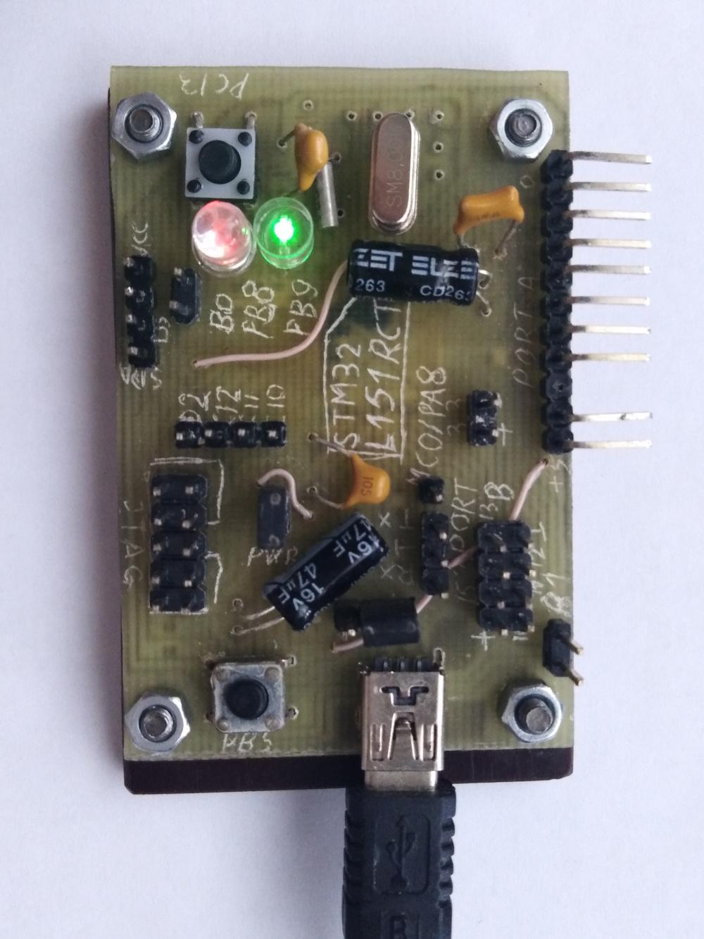
But it is time to poke a stick and in their older brothers - ARM. The choice of a particular family was long and passive (because there is no direct need, that's not in a hurry), but in the end it ended up on stm32f1, as if it were, perhaps, raspiarennom. Buy a programmer, a debugging board like Discovery or a blue pill? What are you, I'm the same AVR-cam master! Any fee can be made LUT, and even as you need, without too much weight. Therefore, I buy naked stm32f103c8t6 and begin to shamanize with the trace of the board. What do I need? At least two ports on the combs ... oops, withdraw ports entirely uncomfortable. Yes, okay, I will bring out 8 legs - from the port A the younger ones (0-7), from B - the older ones (8-15). Still, of course, LEDs and buttons, as without display and control. That's what surprises me in the ready-made debug boards so the absence of at least 2-3 LEDs and 1-2 buttons that would not conflict with anything. How do they even imagine debugging? Under the buttons themselves are asked PA8, PA9, they are conveniently located. Another useful USB, jumpers BOOT0, BOOT1 and battery connector for hours. And connectors for quartz, so very beautiful (later never used the connectors for quartz). To power the controller, you need no more than 3.6 V, and with USB goes 5 V. You need to install a stabilizer. I read a lot how people choose stabilizers with low voltage drops ... why? The difference is one and a half volts, but here there is enough oak 78l33. And now the JTAG connector. Atmel programming connector was a standard ISP10 or ISP6. Probably JTAG is also standard. It turns out, yes ... but only for a separate manufacturer or even a device. We look at the connector on the st-link: beautiful, 10-pin. We look at some programmer for AVR: oops, already 20-pin. We look somewhere else: more incompatible connectors to god of incompatible standards. Well, if so, we will invent our own. If anything, the adapter between them will be no more difficult than an ISP-6 adapter on an ISP-10. It seems that everything is ready, you can make a fee. As it turned out, the 0.5 mm pitch is quite achievable at the amateur level, it was not even necessary to paint almost with a marker.
Now than to stitch it. Since there is USB, probably, it can do it. I read the datasheet - yeah, it does not know how via USB, but it does through UART1. Oops, I forgot to withdraw it. Moreover, it also conflicts with the button, with the one that hangs on PA9. Well, okay, I will bring it out on the wiring, but there is still one more button. A bit of shamanism and the board is ready and even defined in stm32flash.

It seems to have figured out the iron, it's time to move on to the code. After reading several articles on the Internet, I found a ready-made archive for gcc-arm-none-eabi. To figure out exactly how to set the assembly sequence, I will later. So far I'm doing hello-worlds on buttons and LEDs. Since this is my first acquaintance with this family, no wrappers like HAL are just manual work with registers. However, this is quite a natural approach, it seems to me, it was possible not to mention. A little annoying all the time to pull the power and BOOT0 on the board, but oh well, someday I will do a JTAG programmer. Oddly enough, the rake with disabled peripheral clocking did not come. I remembered my youth when I wrote three-dimensional graphics processing on TurboPascal. Here I have a display on ili9341 from raspberry pi and a controller as much as 72 MHz. That's what happened - up to 200 points per model and 11 fps. Of course, all transformation matrices are counted in fixed-point numbers.
At some point, I wanted to make a wearable device so that it would work on battery for a long time. I looked at the datasheet and was upset: the famous ARM for consumption is several times worse than the same AVR-ok! If the second (poked into the first controller that turned out to be the ATmega88p) consumes 0.8 μA per clock, then the first even in the most economical sleep mode * - 25 μA ± 1.4 μA on the RTC. This is no good. However, stm32f103 is not positioned as an economical series. I look on the STmicroelectronics website for other series of controllers and choose the stm32l1 series: in addition to the consumption of about 1 μA, there is also a capacitive sensor and LCD controller. True, the maximum frequency is smaller, only 36 MHz (or 24 MHz if USB is used), but I'll survive it somehow. It was decided: I take a pair of stm32l151rct6 as much as 32 KB of RAM (there is still 256 KB of flash, but I have little idea how it can be hammered. Unless absolutely wild govnokodom or arrays of data).
- ) do not confuse sleep modes (sleep, stop) with disconnecting (standby)
At the same time, I make a st-link v2 programmer from a spare stm32f103, simply because I am tired of messing with BOOT0 and power, and even faster it. However, I will leave UART programming - you never know. There was also a bit of shamanism, but nothing outstanding. Unless finding the command line for openocd turned out to be a problem. For future generations I will leave it:
openocd -f interface/stlink-v2.cfg -f target/stm32f1x.cfg -c "init" -c "reset halt" -c "flash write_image erase "$(firmware).bin" 0x08000000" -c "reset run" -c "exit" For stm32l151 it is necessary, of course, to correct the target to "target / stm32l1.cfg"

Slightly running forward in chronology, but not to return. Gentlemen, do not save on textolite thickness! Or at least add props, or do not use smd-components. It so happened that on the programmer board I provided only two mounting holes in random places. And the places were quite far from the JTAG connector. And after some time, I noticed that the programmer is unstable. It works, it does not, then through the UART you have to erase the "victim", then pick up. It turned out that the resistor, going from the output of the controller to the connector, broke down. He simply fell off the contact pad from the case. I soldered the resistor. Then he soldered the rest. Then he guessed that even the small deformation of the board, which occurred during the sticking-pulling out of the cable, was enough for the unfortunate components. As a result, stuck a backup right next to the connector. While holding.
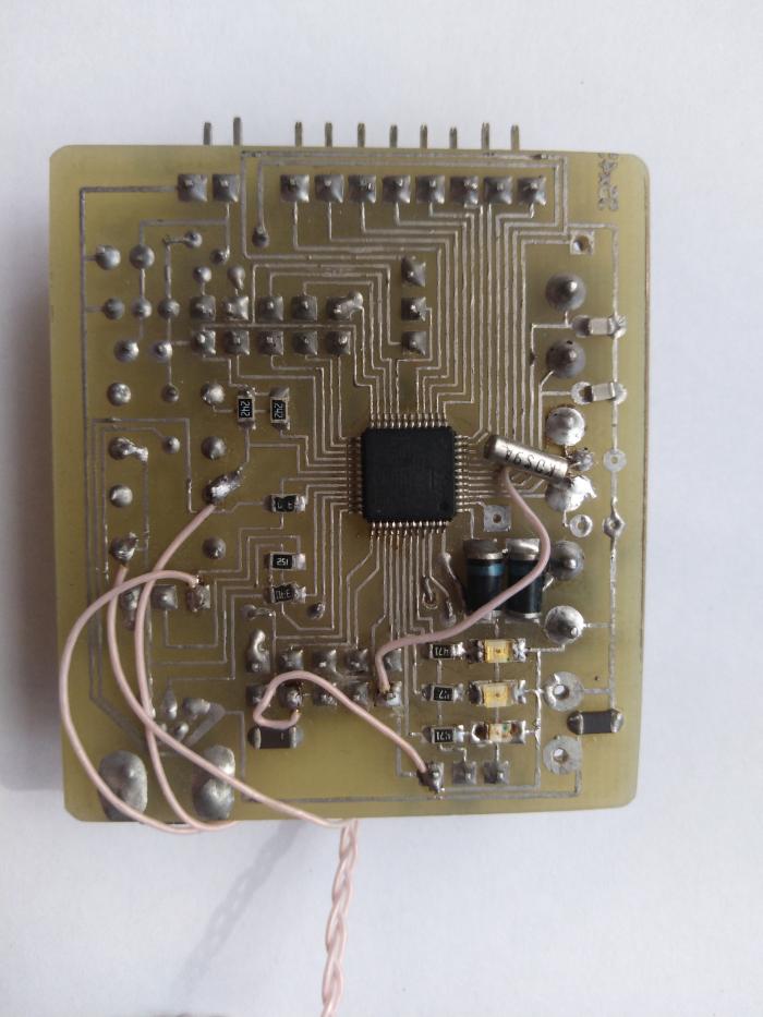
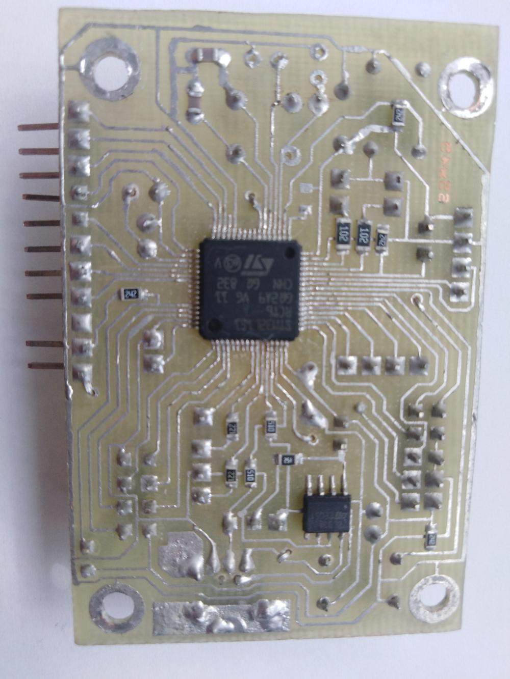
As the reader has already guessed, programming still goes in a text editor, while compilation and firmware are in the console. Naturally, the purchased debugging board for l151 inspired me no more than any IDE. Rubbing the traces of the rake left by the first board, I breed the second one (considering the programmer to be the third, but it is not a debug board). Since I am about to debug an energy-efficient device, I need to be confused with power. I will not change the 78l33 stabilizer, but I ripped the output with a jumper so that I could get stuck with an ammeter (I hope, nevertheless, for a microammeter, but how it goes there). Let combs be the same as on the previous board - compatibility! Well, a couple of LEDs and buttons, of course. The rake with UART1 glitters appealingly, but I still put its connector and do not get it on my forehead. Of course, I already have JTAG, but insurance doesn't hurt. Just like the previous one (and the programmer board, too) managed to be diluted on the same side, not even too many jumpers.
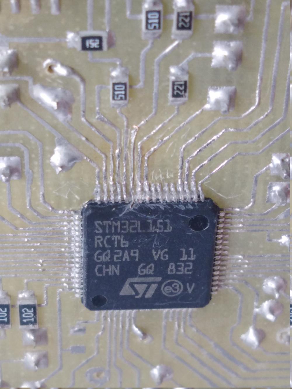
But when soldering the controller there was a problem. I somehow naively believed that the body of the microcircuit should have a key denoting the first leg. Who would expect that the greats from ST will make TWO keys, symmetrically. So which side to solder it now? Thinking, I decided that these were not keys, but technological grooves. You never know, for the positioning of the chip in the manufacture, for example. Or press the base to fill with plastic. Then you need to navigate by the inscription. It is logical that the inscription should be readable if the chip is positioned "standard", that is, when the first leg is in the upper left corner. So he began to solder. Whether the defect is LUT, or the crooked hands, but the microcircuit is soldered crookedly, the benefit was noticed in time, before it was completely sealed. It does not matter, there is an old way of soldering centipedes with a razor blade: it is not wetted by solder and thin enough so as not to bend too much. It turned out that the hands were not straight enough, because the legs were bent. But not up, but to the side, it is good though not much and they managed to straighten them somehow. The second attempt at sealing was already under a microscope, but before that I decided to correct the legs. And one of them broke off. What are they made of, that one cannot bend or bend once? Output components have no such problem. Well, everything, I think, the chip in marriage, will have to solder another. But suddenly it is not a critical leg? Well there, general purpose output, or one of the meals. So far I solder without it, but we'll see. This time, I managed to solder exactly, although the leg got on the I2C, with which I wanted to have fun, but at least not on vital connectors like USB, JTAG, UART or BOOT. I connect - it does not work, the programmers do not see the board. For a time, the shaman with the legs disappearing, but it does not help. Wandering on datasheet view stumbles on the picture of the controller, located somewhere in the basement of the document. Here's how it was possible to come up with the inscription SIDE! That is, if you turn the controller so that the inscription is read, the first leg will be in the lower left corner. Along the way, it turned out that one of the "technological grooves" is still the key. However, it is not explained how to distinguish it from the symmetric ... Well, at least some kind of clue. I take out the controller with a building hairdryer so as not to break the conclusions, and this time I seal it sideways. The broken output falls exactly on the TX output of the UART1, that is, on the programming and debugging connector. This is not good at all, but before changing the controller, you should at least make sure that you are guided by orientation so that when re-soldering to live it should not be killed by improper connection. I connect the programmer - it works. Hooray. Little things remained - to solder the connectors, diodes and other strapping. In the comments suggested another way - to ring the ground: they are usually connected inside the case and are not completely symmetrical. However, taking into account the step of conclusions, it can be difficult to get on the necessary conclusions. Anyway, it is the most reliable way.
I don’t want to work with the controller without UART1, and it’s not going to be any worse now. And if it does, it will still change, so I make a decision to play with the surgeon and make the controller a prosthetic leg from the MGTP hair. Just at hand, there is a good conductive glue lying around, with which the hair resolutely clings to the area on the microchip body. The glue that fell on the neighboring legs is ruthlessly removed with a scalpel. And what do you want to get into the half-millimeter platform and not to get on the adjacent protruding legs? I check - it works. Until it fell off, but in order not to fall off and then, I poured it with cyanoacrylate.
Perhaps I would have used this board if the leg had not fallen off again. And she is covered with glue. However, it is quite soft and is cut with a scalpel, so it is successfully brushed off. But for some reason I don’t want to use the same conductive glue for the second time. I'll try to solder a leg. The usual soldering iron tip didn’t crawl in there, but the bundle was tapered (actually, the tapered was originally the only one, but due to its obvious inconvenience, it was replaced with the usual one, with a wedge-shaped sharpening), which crawls there completely. Strangely enough, the "operation of transplantation" was successful and the leg earned as it should be (close-up picture of the leg on KDPV).
So, iron is ready, it's time to go to the code. It would be nice to find a ready-made example for gcc and the CMSIS library. What is better for this than the official website of the manufacturer? As it turned out, STmicroelectronics does not share my optimism. The fact that navigation on the site is done through an indecent place is already familiar, now it is difficult to find a site made by people for people. But they do not allow you to download anything from the site! It would have been possible after registration, but I had no desire to register anywhere before, and after such an attitude towards developers, even more so. Why do you need my mail or what do you need there? Collect personal data, send spam? Go through the forest, and I will find it freely available! By the way, I was a little surprised that the corresponding package was not in the repository, but perhaps ST came up with some kind of licensed hemorrhoids. Therefore, I send the rays of diarrhea to marketers who have invented such a policy, and for an inconvenient site too.
Anyway, the library was perfectly found on the Internet (I will not give links, you never know what will happen with the site). An alternative is to download the development environment or CubeMX, where these libraries are embedded. True, download them from the official site is just as impossible, so we are looking for third-party and install it on a virtual machine, just in case of “if suddenly something”.
With iron sorted out, with sorts too. It's time to finally deal with the controller. The first surprise was waiting when trying to use third-party code under Discovery. It uses the stm32l152 controller, which at first glance hardly differs from the stm32l151 installed by me. In addition to minor differences, it turned out that the LCD module was not installed in the "my" controller. A little sad, but I still did not plan to use it. Although such a difference could be more clearly distinguished than with the note in the datasheet. By the way, it is recommended in this case to connect the VLCD output with power, in my photo the corresponding 0-ohm resistor is not sealed, but in reality I still installed it. Without it, it also works, but you should not overload internal connections. More interesting was the behavior of a real-time clock. They stubbornly did not want to work, and on the Internet they simply write “do it, do it, it works.” And it does not work. In some places, however, it was mentioned about "known problems with the RTC in this series." Be that as it may, the clock still wound up, however, only on the built-in RC-generator. Attempts to make quartz an hour led to the endless waiting for the LSE readiness bit. I tried to check whether the legs of the microcircuit fell off the tracks on the board and pulled them in the usual GPIO mode. Fell off high-frequency quartz. WTF ?! In general, together, these two quartz do not want to work, but at least separately at least they function.
And then I guessed: superglue, which was filled with half of the controller (it’s liquid, you can’t put it on point, and who would have thought ...) leaks and the quartz interfere with each other. Well, outside it is not difficult to scrape the glue, but after all, it got numbed, even under the bottom of the chip. And if there are enough leaks on it for quartz, that will affect consumption. I am looking for in Google than people remove cyanoacrylate. Warm water (what ???) and dimethyl sulfoxide are offered. I do not believe in warm water, so I buy DMSO. After more than an hour of finding a drop of chemical on the surface of the glue, I did not notice the difference. But they noticed quartz and began to work more or less normally (I wonder why? Dimexide displaced moisture absorbed by glue?). However, this did not convince me, and the remnants of the glue still make my eyes callous ... even though they are on the underside of the board and are not particularly visible. By the way, the warm water, which I washed off dimexide, did not affect the glue (I'm not surprised). Found that there is such a thing as a glue remover, in the same tube as the glue itself, only purple. Well, at least it should work! As it turned out, it can and does work, but by its consistency it resembles sour cream and simply does not fit under the microcircuit. So what's the use with you, the remover ?! I can clean it outside. Last chance: Acetone is occasionally mentioned. A little bit afraid for plastic parts, but just to replace them is easy. Pour acetone in a glass jar, throw the board there and leave for the night. The next morning it turned out that acetone really works, and how! From the glue is not even a trace. Moreover, the pusher of one of the buttons dissolved. Interestingly, the second survived, probably, was made of a more sustainable plastic. I was a little surprised that the other plastic remained intact, even the inscriptions survived. Well, well, and the button can be replaced.
Now we managed to launch RTC from the watch quartz, touch the sleep mode, and communicate with other peripherals. And also, so that it would be completely feng shui, put a signature on the board. But not with a marker (suddenly bathing again in solvents?), But scratched with a scalpel. For centuries!
Well, for future generations I will leave code samples for both controllers, along with libraries, makefiles and so on. It only remains to install gcc-arm-none-eabi, openocd, stm32flash and other trifles.
stm32f103
stm32l151
In the comments several times advised not to do LUTom and order the manufacture of boards from professionals. For prototyping, as here - I see no point. Another thing is if you need multi-layered boards, or even a smaller step, or a BGA package, or something else that is difficult to do at home. And, of course, in the manufacture of the final version of the device and replication. It is not good if the customer disassembles the case. textolite welded, and find crooked sawn off the board without a mask and with jumpers from MGTF.
Findings:
- You can make debugging boards for yourself if you wish, they are no worse than purchased ones. But the programmer-debugger is still better to buy if it is not too expensive. Of course, you can make it, but you will not change the scheme, and if it is so, it will not be better bought. Cheaper, most likely, too. Is that if the controller is left over or with the delivery of the problem.
- Do not forget about the backup programming connector UART1, well, at the same time jumpers BOOT0, BOOT1. In addition to programming itself, it is quite convenient to debug a program using UART.
- On the LQFP64 package there are two keys, one of which is fake. Will have to navigate to the inscription to look feet to the left.
- Soldering components with a small step is only under a microscope. Otherwise, it is difficult to determine whether everything was soldered and whether there are any "snot". Well, either on the "professional" equipment like a special dryer, solder paste, etc. I don’t know, I’m writing about amateur technology.
- Do not save on PCB thickness. It bends and this may be enough to damage the smd resistors and, probably, capacitors. Lead is not scary, and components with bent pins (transistors, microcircuits), perhaps, will survive.
- Making connectors for quartz is a waste of time. You will not change them, so just solder to the board.
- Soldering a centipede with a razor blade is only in the most extreme case, when there is no hair dryer. Otherwise, the risk of damage is too great.
- Even if the chip fell off the leg, it can be restored! Even when the pitch is 0.5 mm. The main thing is to use soldering, not conductive glue.
- Never fill the chip with cyanacrylate glue (superglue)! It does not have the proper electrical, and mechanical, characteristics.
- Acetone is best for removing superglue from hard to reach places. Dissolves completely. The main thing is to make sure that the surrounding components are not affected. From inaccessible places and can be mechanically removed.
')
Source: https://habr.com/ru/post/456280/
All Articles