Aviation gas turbine engines
Hello! In this article I want to talk about how aviation gas turbine engines (GTE) work. I will try to make it the most simple and understandable language.
Aviation GTE can be divided into:
Moreover, the turbofan engines and turbofan engines can contain an afterburner chamber, in which case they will be turbofan engines and turbofan engines, respectively. In this article we will not consider them.
')
Let's start with the turbojet engines.
This type of engine was created in the first half of the 20th century and began to find massive use for itself by the end of World War II. The world's first serial turbojet aircraft was the German Me.262. TRDs were popular until the 60s, after which they began to be crowded out by the TRDD.
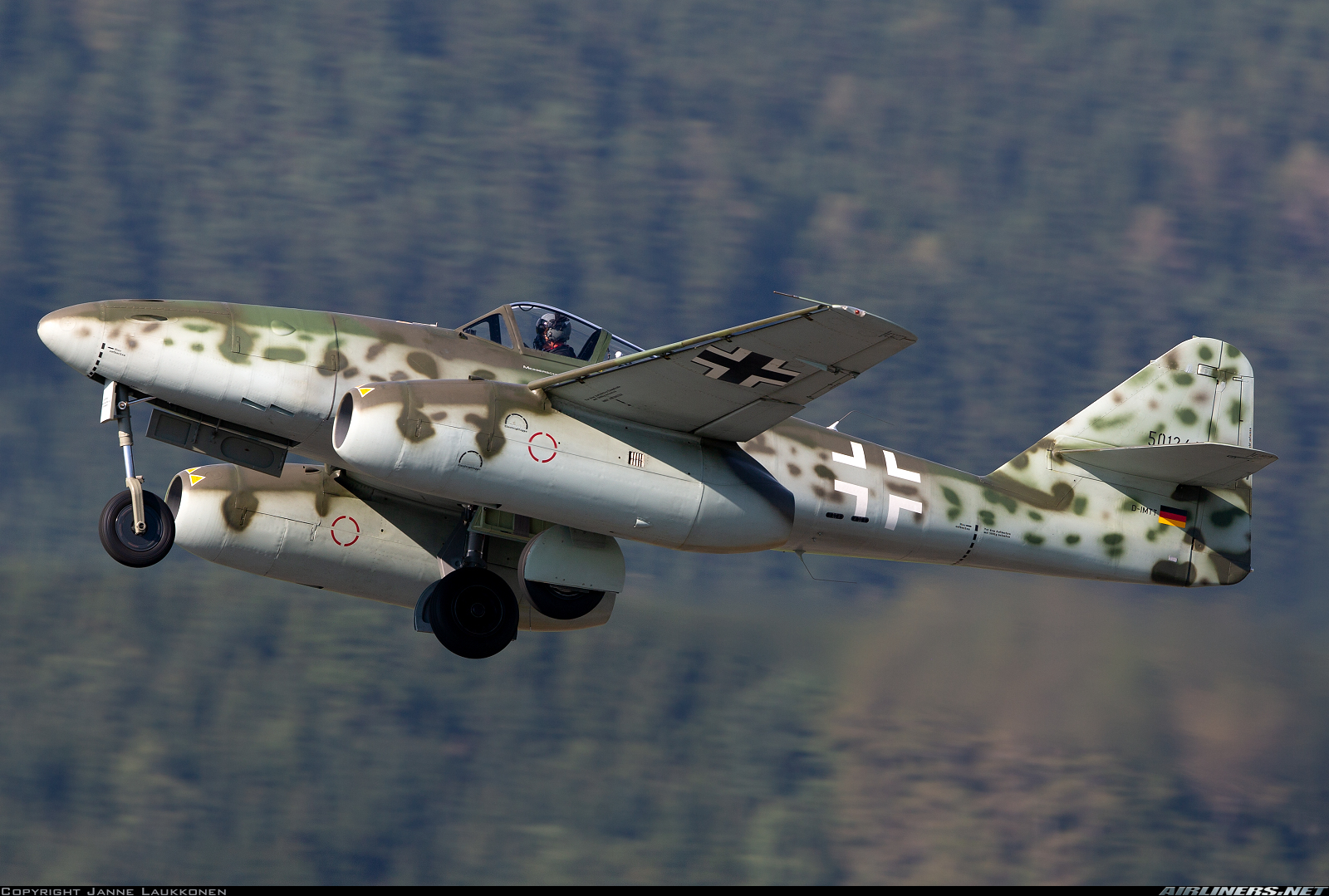
Modern photo of Me-262, made in 2016
The simplest turbojet engine includes the following elements:
We can say that this is the minimum set for normal engine operation.
And now we will consider what is needed and why.
The inlet is an expanding * channel in which air is supplied to the compressor and is pre-compressed. In it, the kinetic energy of the incoming air is partially converted into pressure.
* hereinafter we will talk about subsonic speeds. At supersonic speed, physics changes, and everything is completely different there.
A compressor is a device in which air pressure rises. The compressor can be characterized by such a value as the degree of pressure increase. In modern engines, it is already beginning to cross over 40 units. In addition, it increases the temperature (maybe somewhere up to 400 degrees Celsius).
The combustion chamber is a device in which heat is supplied to the compressed air (after the compressor) due to the combustion of the fuel. The temperature in the combustion chamber is very high, can reach 2000 degrees Celsius. It may seem to you that the gas pressure in the chamber also increases greatly, but it is not. It is theoretically accepted that heat is applied at constant pressure. In reality, it falls slightly due to losses (the problem of imperfect structures).
A turbine is a device that converts a part of the energy of a gas after the combustion chamber into the energy of a compressor drive. Since turbines are used not only in aviation, a more general definition can be given: this is a device that converts the internal energy of a working fluid (in our case, the working fluid is gas) into mechanical work on the shaft. As you could understand, the turbine and compressor are on the same shaft and are rigidly connected to each other. If in the compressor there is an increase in gas pressure, then in the turbine, on the contrary, a decrease, that is, the gas expands.
A nozzle is a narrowing channel in which the potential energy of a gas is converted into kinetic (the remaining energy of the gas after the turbine). As in the turbine, gas expansion occurs in the nozzle. Formed jet, which, emerging from the nozzle, moving the plane.
With the main elements sorted out. But still not very clear how it works? Then let's do it again and briefly.
Air from the atmosphere enters the inlet device, where it is compressed slightly and enters the compressor. In the compressor, the air pressure grows even stronger, and the temperature rises. After the compressor, the air enters the combustion chamber and, mixing there with fuel, ignites, which leads to a strong increase in temperature, at, it can be said, constant pressure. After the combustion chamber hot compressed gas enters the turbine. Part of the gas energy is consumed by the turbine to rotate the compressor (so that it can perform its function described above), another part of the energy is spent on the aircraft movement we need, because the gas, passing through the turbine, turns into a jet stream in the nozzle and breaks out of it (nozzle) into the atmosphere. The cycle ends here. Of course, in reality, all processes of the cycle are continuous.
Such a cycle is called a Brighton cycle, or a thermodynamic cycle with a continuous nature of the working process and heat input at constant pressure. According to this cycle, all GTE work.
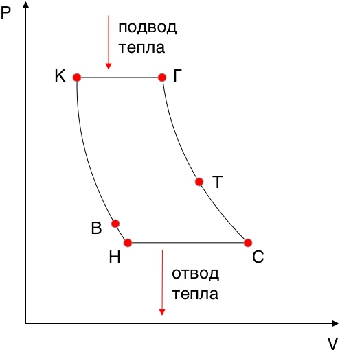
Brighton cycle in PV coordinates
HB - the compression process in the input device
In-to - compression process in the compressor
KG - Isobaric heat supply
- gas expansion process in a turbine
Gs - the process of gas expansion in the nozzle
- - isobaric heat removal to the atmosphere
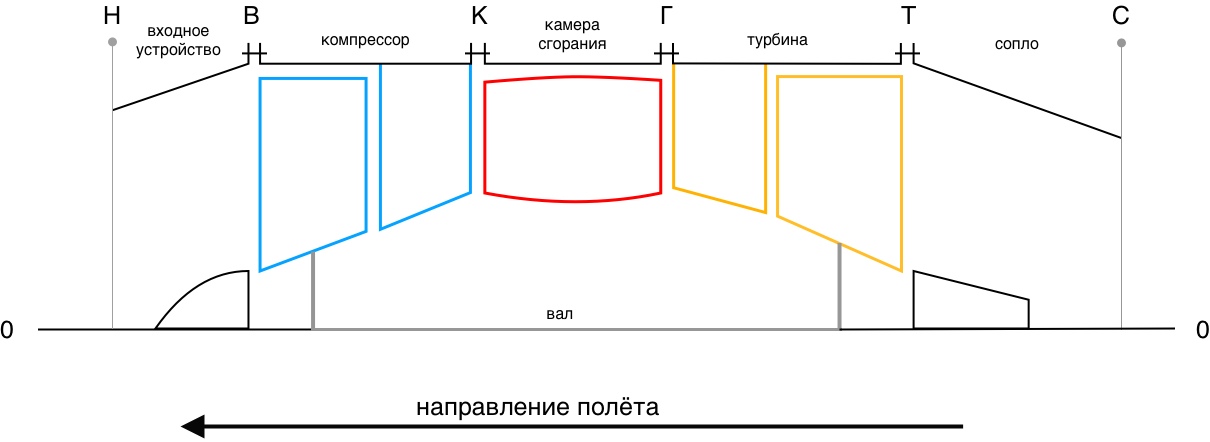
The schematic design of the turbojet engine, where 0-0 is the axis of the engine
TRD may have two shafts. In this case, the compressor consists of a low pressure compressor (LPC) and a high pressure compressor (HPC), and the work will be supplied by a low pressure turbine (LPT) and a high pressure turbine (HPD), respectively. Such a scheme is more favorable gas-dynamic.
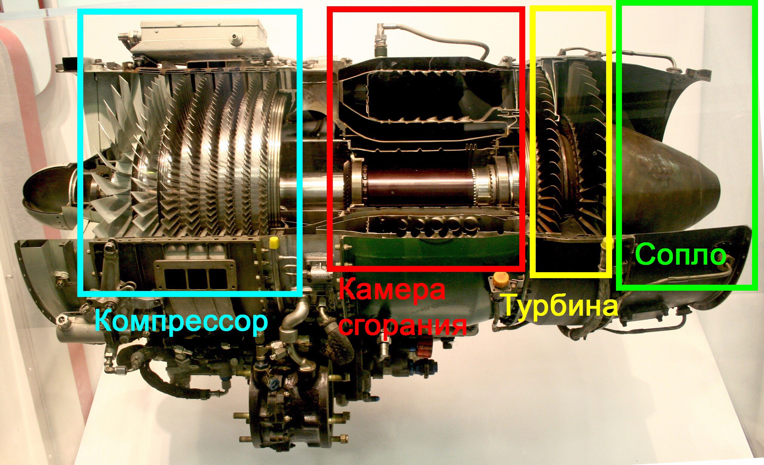
Real engine of this type in section
We considered the principle of operation of the simplest scheme of an aircraft gas turbine engine. Naturally, on modern "Airbus and Boeing" are established TRDD, the design of which is much more complicated, but it all works according to the same laws. Let's look at them.
TRD, above all, differs from TRD in that it has two circuits: external and internal. The inner loop contains the same thing as a turbofan engine: a compressor (divided into LPC and high-pressure boiler), a combustion chamber, a turbine (divided into TVD and LPC) and a nozzle. The outer contour is a channel with a nozzle at the end. There is no combustion chamber or turbine in it. Before both circuits (immediately after the engine inlet) is a compressor stage operating on both circuits.
Not very clear picture comes out, right? Let's see how it works.
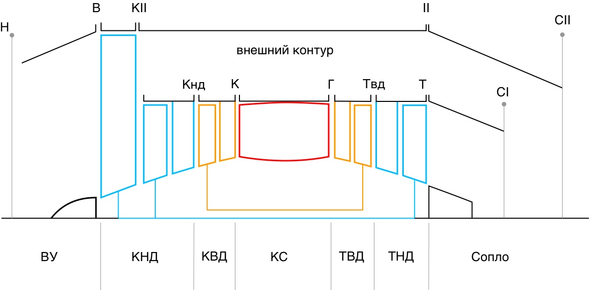
Schematic design of twin-shaft twin-turbojet engine
The air entering the engine, passing through the first stage of the low-pressure compressor, is divided into two streams. One part of the air goes along the internal contour, where the same processes take place that were described when we analyzed the turbofan engines. The second part of the air enters the external circuit, receiving energy from the first stage of the LPC (the one that operates on two circuits). In the external circuit, the energy of air is spent only on overcoming hydraulic losses (due to friction). At the end of this air enters the nozzle of the external circuit, creating a huge thrust. The thrust created by the external circuit may be 80% of the thrust of the entire engine.
One of the most important characteristics of turbofan is the degree of bypass. The degree of bypass is the ratio of the air flow in the external circuit to the air flow in the internal circuit. This number can be either greater or less than one. On modern engines, this number transcends the value of 12 units.
Engines with a greater than two bypass ratio are usually called turbofans, and the first compressor stage (the one that runs on both circuits) is a fan.
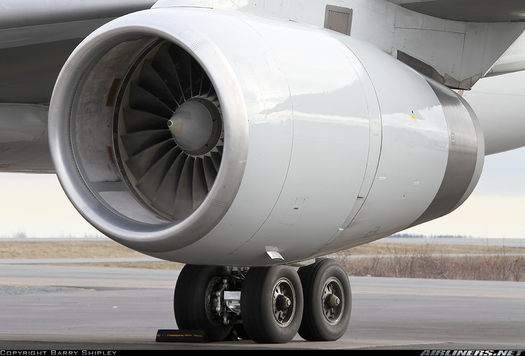
TRDD aircraft Boeing 757-200. In the foreground you can see the input device and the fan
On some engines, the fan is driven by a separate turbine, which is placed closest to the nozzle of the internal circuit. Then the engine turns three-shaft. For example, according to this scheme, the engines Rolls Royce RB211 (installed on L1011, B747, B757, B767), D-18T (An-124), D-36 (Yak-42)
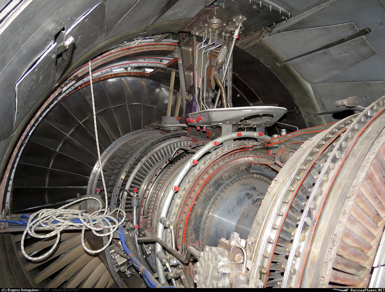
D-18T in the context of the inside
The main advantage of the turbofan engines is the ability to create a lot of traction and good economy, compared with the TRD.
At this point, I would like to finish about TRD and move on to the next engine type, theater engines.
Turboprop engine, like turbojet, refers to gas turbine engines. And it works almost like a turbojet. The elementary turboprop engine consists of the elements already familiar to us: a compressor, a combustion chamber, a turbine and a nozzle. They are added gear and screw.
The principle of operation is the same as that of a turbojet, with the difference that almost all the gas energy is spent on the turbine to rotate the compressor and to rotate the screw through the gearbox (here the screw and gearbox are on the same shaft as the compressor). Screw creates the bulk of the thrust. The remaining, after the turbine, part of the energy is sent to the nozzle, forming a jet thrust, but it is small, it can be a tenth of the total. The reducer in this scheme is needed in order to lower the revolutions and transfer the moment, since the turbine can rotate with a very high frequency, for example, 10,000 revolutions per minute, and the screw only needs 1500. And the screw is rather heavy.
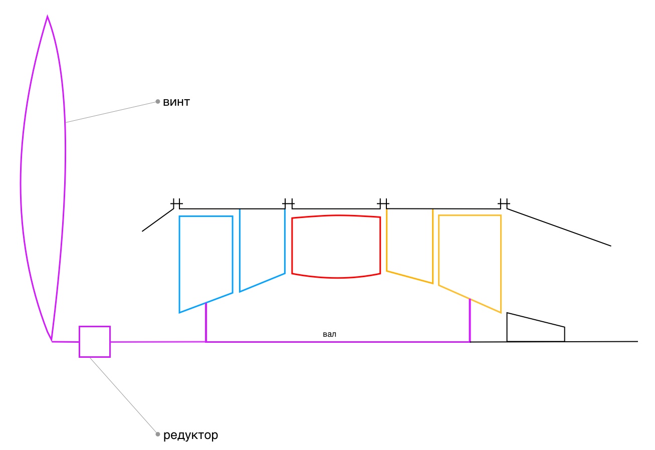
The schematic design of the theater
But there is another scheme of turboprop engines: with a free turbine.
Its essence is that a separate turbine is placed behind a conventional compressor turbine, which is not mechanically connected to the compressor turbine. Such a turbine is called free. The connection between the compressor turbine and the free turbine is only gas-dynamic. From the free turbine there is a separate shaft on which the gearbox with the screw is installed. Everything else works the same as in the first case. Most modern engines perform exactly according to this scheme. One of the advantages of this scheme is the possibility of using the engine on the ground, as an auxiliary power unit (APU), without setting the propeller in motion.
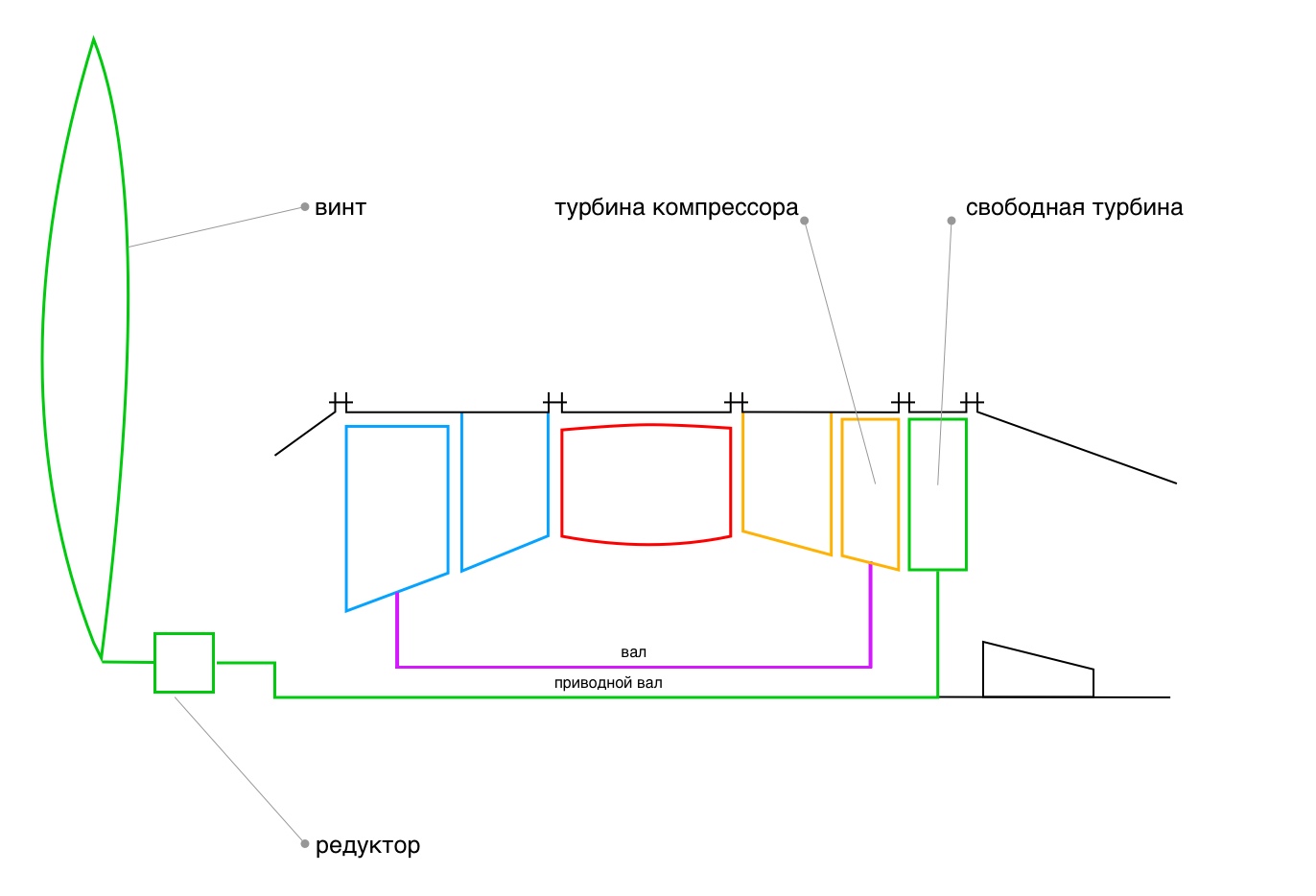
Schematic design of the turbofan free turbine
I want to note that you do not need to look at turboprop engines as an inefficient relic of the past. I have heard such statements several times, but they are incorrect.
Turboprop engine in some cases has the highest efficiency, usually on aircraft with not very high speeds (for example, at 500 km / h), moreover, the aircraft can be impressive sizes. In this case, a turboprop engine can be several times more advantageous than the turbojet engine discussed earlier.
On this pro turboprop engines can be completed. We slowly came to the concept of a turboshaft engine.
It must be that most readers here hear such a name for the first time. This type of engine is installed on helicopters.
A turboshaft engine is very similar to a turboprop engine with a free turbine. It also consists of a compressor, a combustion chamber, a compressor turbine, then comes a free turbine, associated with all the preceding gas-dynamic only. But this engine does not create jet thrust, it does not have a jet nozzle, only exhaust. The free turbine has its own shaft, which is connected to the main gearbox of the helicopter (rotor). Yes, all helicopters known to me have such a gear, and, as a rule, it is of impressive size. The fact is that the rotor speed of the helicopter is very low. If the aircraft, as I wrote above, they can reach 1500 r / min, then the helicopter, for example, the Mi-8, only 193 r / min.
And the engine revolutions of a helicopter are often very high (due to its small size), and they have to be reduced a hundred or more times. It happens that the gearbox is on the engine and on the helicopter itself, for example, in the Mi-2 and its GTD-350 engine.

The schematic design of the turboshaft engine
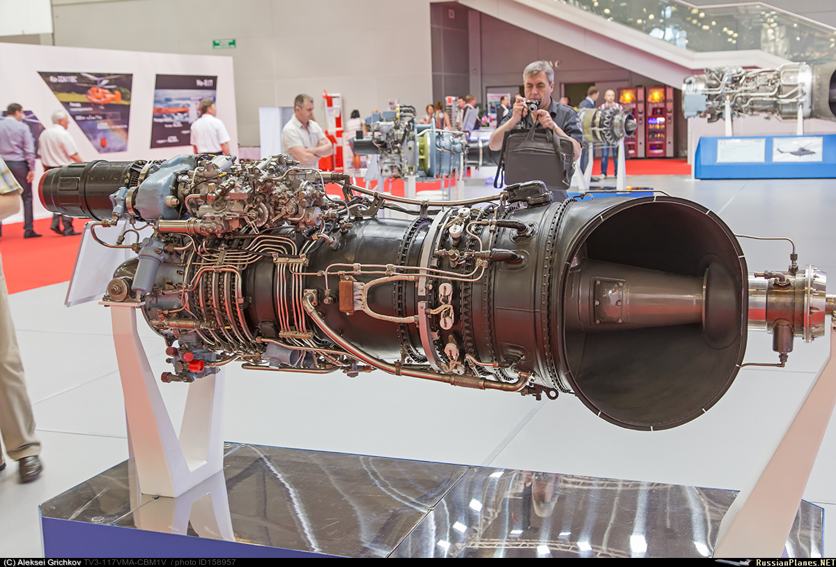
The TV3-117 engine from the Mi-8 helicopter. The exhaust pipe and the drive shaft are visible on the right.
So, we looked at four types of gas turbine engines. I hope my text was clear and useful to you. All questions and comments can write in the comments.
Thanks for attention.
Aviation GTE can be divided into:
- turbojet engines (TRD)
- turbojet engines (TRD)
- Turboprop engines (TVD)
- Turboshaft engines (TWP)
Moreover, the turbofan engines and turbofan engines can contain an afterburner chamber, in which case they will be turbofan engines and turbofan engines, respectively. In this article we will not consider them.
')
Let's start with the turbojet engines.
Turbojet engines
This type of engine was created in the first half of the 20th century and began to find massive use for itself by the end of World War II. The world's first serial turbojet aircraft was the German Me.262. TRDs were popular until the 60s, after which they began to be crowded out by the TRDD.
Modern photo of Me-262, made in 2016
The simplest turbojet engine includes the following elements:
- Input device
- Compressor
- Combustion chamber
- Turbine
- Jet nozzle (hereinafter simply nozzle)
We can say that this is the minimum set for normal engine operation.
And now we will consider what is needed and why.
The inlet is an expanding * channel in which air is supplied to the compressor and is pre-compressed. In it, the kinetic energy of the incoming air is partially converted into pressure.
* hereinafter we will talk about subsonic speeds. At supersonic speed, physics changes, and everything is completely different there.
A compressor is a device in which air pressure rises. The compressor can be characterized by such a value as the degree of pressure increase. In modern engines, it is already beginning to cross over 40 units. In addition, it increases the temperature (maybe somewhere up to 400 degrees Celsius).
The combustion chamber is a device in which heat is supplied to the compressed air (after the compressor) due to the combustion of the fuel. The temperature in the combustion chamber is very high, can reach 2000 degrees Celsius. It may seem to you that the gas pressure in the chamber also increases greatly, but it is not. It is theoretically accepted that heat is applied at constant pressure. In reality, it falls slightly due to losses (the problem of imperfect structures).
A turbine is a device that converts a part of the energy of a gas after the combustion chamber into the energy of a compressor drive. Since turbines are used not only in aviation, a more general definition can be given: this is a device that converts the internal energy of a working fluid (in our case, the working fluid is gas) into mechanical work on the shaft. As you could understand, the turbine and compressor are on the same shaft and are rigidly connected to each other. If in the compressor there is an increase in gas pressure, then in the turbine, on the contrary, a decrease, that is, the gas expands.
A nozzle is a narrowing channel in which the potential energy of a gas is converted into kinetic (the remaining energy of the gas after the turbine). As in the turbine, gas expansion occurs in the nozzle. Formed jet, which, emerging from the nozzle, moving the plane.
With the main elements sorted out. But still not very clear how it works? Then let's do it again and briefly.
Air from the atmosphere enters the inlet device, where it is compressed slightly and enters the compressor. In the compressor, the air pressure grows even stronger, and the temperature rises. After the compressor, the air enters the combustion chamber and, mixing there with fuel, ignites, which leads to a strong increase in temperature, at, it can be said, constant pressure. After the combustion chamber hot compressed gas enters the turbine. Part of the gas energy is consumed by the turbine to rotate the compressor (so that it can perform its function described above), another part of the energy is spent on the aircraft movement we need, because the gas, passing through the turbine, turns into a jet stream in the nozzle and breaks out of it (nozzle) into the atmosphere. The cycle ends here. Of course, in reality, all processes of the cycle are continuous.
Such a cycle is called a Brighton cycle, or a thermodynamic cycle with a continuous nature of the working process and heat input at constant pressure. According to this cycle, all GTE work.
Brighton cycle in PV coordinates
HB - the compression process in the input device
In-to - compression process in the compressor
KG - Isobaric heat supply
- gas expansion process in a turbine
Gs - the process of gas expansion in the nozzle
- - isobaric heat removal to the atmosphere
The schematic design of the turbojet engine, where 0-0 is the axis of the engine
TRD may have two shafts. In this case, the compressor consists of a low pressure compressor (LPC) and a high pressure compressor (HPC), and the work will be supplied by a low pressure turbine (LPT) and a high pressure turbine (HPD), respectively. Such a scheme is more favorable gas-dynamic.
Real engine of this type in section
We considered the principle of operation of the simplest scheme of an aircraft gas turbine engine. Naturally, on modern "Airbus and Boeing" are established TRDD, the design of which is much more complicated, but it all works according to the same laws. Let's look at them.
Turbojet dual circuit
TRD, above all, differs from TRD in that it has two circuits: external and internal. The inner loop contains the same thing as a turbofan engine: a compressor (divided into LPC and high-pressure boiler), a combustion chamber, a turbine (divided into TVD and LPC) and a nozzle. The outer contour is a channel with a nozzle at the end. There is no combustion chamber or turbine in it. Before both circuits (immediately after the engine inlet) is a compressor stage operating on both circuits.
Not very clear picture comes out, right? Let's see how it works.
Schematic design of twin-shaft twin-turbojet engine
The air entering the engine, passing through the first stage of the low-pressure compressor, is divided into two streams. One part of the air goes along the internal contour, where the same processes take place that were described when we analyzed the turbofan engines. The second part of the air enters the external circuit, receiving energy from the first stage of the LPC (the one that operates on two circuits). In the external circuit, the energy of air is spent only on overcoming hydraulic losses (due to friction). At the end of this air enters the nozzle of the external circuit, creating a huge thrust. The thrust created by the external circuit may be 80% of the thrust of the entire engine.
One of the most important characteristics of turbofan is the degree of bypass. The degree of bypass is the ratio of the air flow in the external circuit to the air flow in the internal circuit. This number can be either greater or less than one. On modern engines, this number transcends the value of 12 units.
Engines with a greater than two bypass ratio are usually called turbofans, and the first compressor stage (the one that runs on both circuits) is a fan.
TRDD aircraft Boeing 757-200. In the foreground you can see the input device and the fan
On some engines, the fan is driven by a separate turbine, which is placed closest to the nozzle of the internal circuit. Then the engine turns three-shaft. For example, according to this scheme, the engines Rolls Royce RB211 (installed on L1011, B747, B757, B767), D-18T (An-124), D-36 (Yak-42)
D-18T in the context of the inside
The main advantage of the turbofan engines is the ability to create a lot of traction and good economy, compared with the TRD.
At this point, I would like to finish about TRD and move on to the next engine type, theater engines.
Turboprop engines
Turboprop engine, like turbojet, refers to gas turbine engines. And it works almost like a turbojet. The elementary turboprop engine consists of the elements already familiar to us: a compressor, a combustion chamber, a turbine and a nozzle. They are added gear and screw.
The principle of operation is the same as that of a turbojet, with the difference that almost all the gas energy is spent on the turbine to rotate the compressor and to rotate the screw through the gearbox (here the screw and gearbox are on the same shaft as the compressor). Screw creates the bulk of the thrust. The remaining, after the turbine, part of the energy is sent to the nozzle, forming a jet thrust, but it is small, it can be a tenth of the total. The reducer in this scheme is needed in order to lower the revolutions and transfer the moment, since the turbine can rotate with a very high frequency, for example, 10,000 revolutions per minute, and the screw only needs 1500. And the screw is rather heavy.
The schematic design of the theater
But there is another scheme of turboprop engines: with a free turbine.
Its essence is that a separate turbine is placed behind a conventional compressor turbine, which is not mechanically connected to the compressor turbine. Such a turbine is called free. The connection between the compressor turbine and the free turbine is only gas-dynamic. From the free turbine there is a separate shaft on which the gearbox with the screw is installed. Everything else works the same as in the first case. Most modern engines perform exactly according to this scheme. One of the advantages of this scheme is the possibility of using the engine on the ground, as an auxiliary power unit (APU), without setting the propeller in motion.
Schematic design of the turbofan free turbine
I want to note that you do not need to look at turboprop engines as an inefficient relic of the past. I have heard such statements several times, but they are incorrect.
Turboprop engine in some cases has the highest efficiency, usually on aircraft with not very high speeds (for example, at 500 km / h), moreover, the aircraft can be impressive sizes. In this case, a turboprop engine can be several times more advantageous than the turbojet engine discussed earlier.
On this pro turboprop engines can be completed. We slowly came to the concept of a turboshaft engine.
Turboshaft engine
It must be that most readers here hear such a name for the first time. This type of engine is installed on helicopters.
A turboshaft engine is very similar to a turboprop engine with a free turbine. It also consists of a compressor, a combustion chamber, a compressor turbine, then comes a free turbine, associated with all the preceding gas-dynamic only. But this engine does not create jet thrust, it does not have a jet nozzle, only exhaust. The free turbine has its own shaft, which is connected to the main gearbox of the helicopter (rotor). Yes, all helicopters known to me have such a gear, and, as a rule, it is of impressive size. The fact is that the rotor speed of the helicopter is very low. If the aircraft, as I wrote above, they can reach 1500 r / min, then the helicopter, for example, the Mi-8, only 193 r / min.
And the engine revolutions of a helicopter are often very high (due to its small size), and they have to be reduced a hundred or more times. It happens that the gearbox is on the engine and on the helicopter itself, for example, in the Mi-2 and its GTD-350 engine.
The schematic design of the turboshaft engine
The TV3-117 engine from the Mi-8 helicopter. The exhaust pipe and the drive shaft are visible on the right.
So, we looked at four types of gas turbine engines. I hope my text was clear and useful to you. All questions and comments can write in the comments.
Thanks for attention.
Source: https://habr.com/ru/post/455774/
All Articles