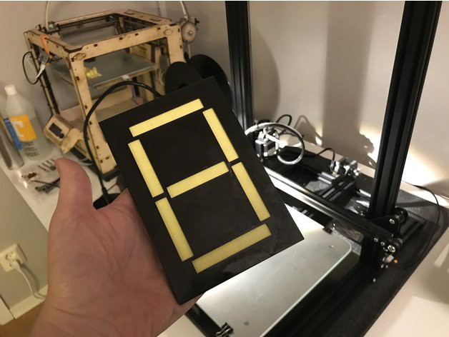
Large mechanical cam display as a decoder
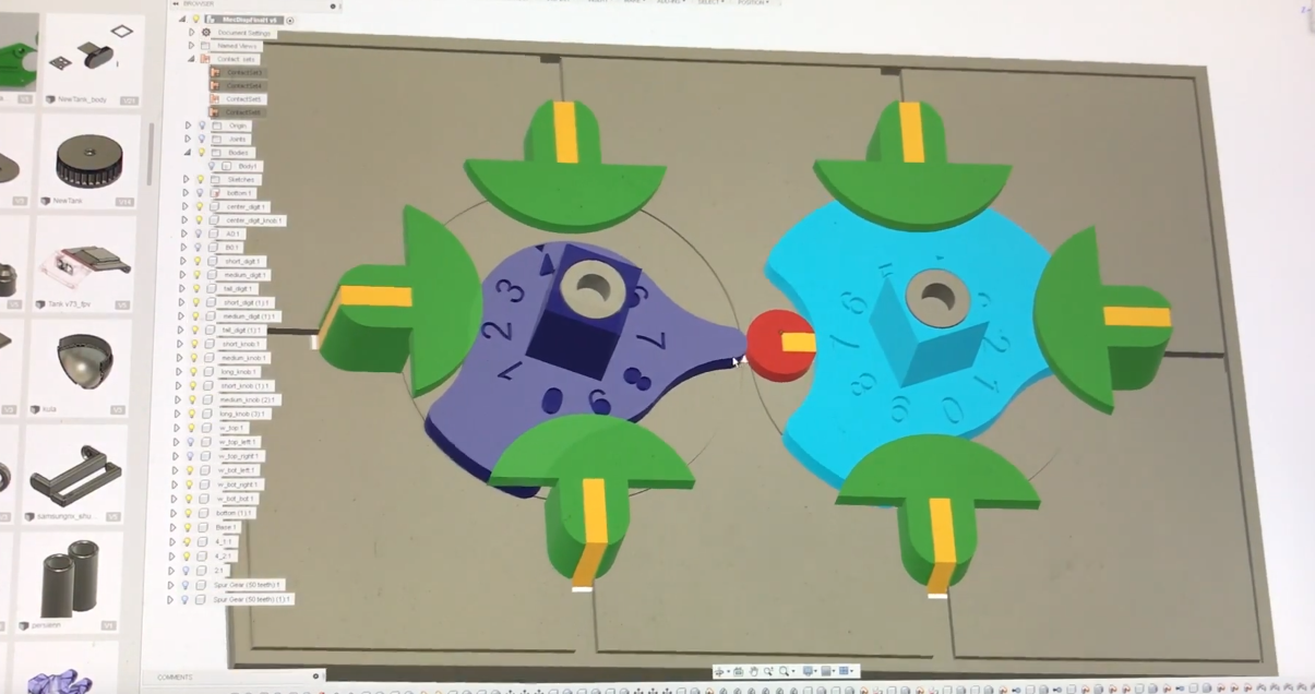
The movement of the segments in this display is controlled by two cams, the rotation of which is synchronized by the gear wheels. All segments except the central one are returned to their original position with a rubber ring, the central one is moved in both directions by the cams.
The kinematic diagram of the display is shown without cogwheels and upper halves of the cams, which would block almost the entire mechanism:
')
STL files are in the same archive , they need to be printed with a layer height of 0.15 mm. Segments should be of a contrasting color with respect to the rest of the details.
Parts of the parts moving in the slots, as well as the slots themselves, can be sharpened with a needle file, but without fanaticism, so that movement in the required directions takes place fairly freely, but there is no skew. It is possible to glue the pushers to all segments, except the central one in advance, to the central one (it is different, its pusher too) - only after installation. It is important to correctly orient the central segment.
Now the most interesting is the cams. Set the lower half of the cams according to the kinematic scheme so that the numbers 7 “look” at each other. Then we set the upper half of the cams (not shown in the kinematic scheme), observing the same condition. Without moving the whole structure, so that they do not move, we put on gear wheels - and now the rotation of the cams is synchronized. And so that all segments except the central one return when the cams are not pressed on their pushers, we wrap them with a rubber ring. It is desirable to slightly lubricate the mechanism, making sure that the oil does not fall on the ring.
The front panel after installing the mechanism in it makes the segments visible only when they coincide with the slots in it.
Timecode to video: 3:21 - 7:26 - an explanation of the principle of the mechanism on the 3D-model, then to the end - the assembly.
Thingiverse device under CC-BY-NC 3.0.
Source: https://habr.com/ru/post/455662/
All Articles