How we designed and implemented a new network on Huawei in the Moscow office, part 1
Today I will talk about how the idea of creating a new internal network for our company appeared and was realized. The position of the leadership - for yourself you need to do the same full-fledged project as for the client. If we do well for ourselves - we can invite the customer and show how well we work and what we offer to him. Therefore, we approached the development of the concept of a new network for the Moscow office very thoroughly, using the full production cycle: analyzing the needs of departments → choosing a technical solution → designing → implementation → testing. So here we go.
The choice of technical solutions: reserve mutants
The order of work on a complex automated system is best described so far in GOST 34.601-90 “Automated systems. Stage of creation ", so we worked on it. And already at the stages of the formation of requirements and the development of a concept, we faced the first difficulties. Organizations of different profiles - banks, insurance companies, software developers, etc. - for their tasks and standards need certain types of networks, the specifics of which are understandable and standardized. However, this is not a ride with us.
')
Why?
Jet Infosystems is a large diversified IT company. At the same time, the internal support department is small (but proud), it ensures the performance of basic services and systems. The company contains many subdivisions that perform different functions: these are several powerful outsourcing teams, and their own developers of business systems, and information security, and architects of computing systems, in general, who just aren't. Accordingly, the tasks, systems and security policies of them are also different. What is expected has created difficulties in the process of analyzing needs and standardizing them.
For example, the development department: its employees write and test the code for a large number of customers. Often there is a need to quickly organize test environments, and frankly, it is not always possible for each project to form requirements, request resources and build a separate test environment in accordance with all internal regulations. This gives rise to funny situations: one day your humble servant looked into the developers room and found a properly functioning Hadoop cluster of 20 desktops under the table, which was inexplicably connected to a common network. I think it is not necessary to clarify that the company's IT department was not aware of its existence. This circumstance, like many others, became the culprits of the fact that during the development of the project, the term “mutant reserve” was born, describing the state of the long-suffering office infrastructure.
Or another example. Periodically, a test bench is built up inside a unit. So it was with Jira and Confluence, which were limitedly used by the Program Development Center in some projects. After some time, we learned about these useful resources in other departments, assessed, and at the end of 2018, Jira and Confluence moved from the status of “local toy programmers” to the status of “company resources”. Now, these systems should have an owner assigned, SLAs should be defined, access / information policies, backup and monitoring policies, rules for routing requests for troubleshooting, in general, all attributes of a complete information system should be present.
Each of our divisions is also an incubator that grows its own products. Some of them die at the development stage, some we use while working on projects, others take root and become replicable solutions, which we begin to apply ourselves and sell to clients. For each such system, it is desirable to have its own network environment, where it will develop without interfering with other systems, and at some point can be integrated into the company's infrastructure.
In addition to the development, we have a very large Service Center with more than 500 employees, formed into teams for each customer. They are engaged in the maintenance of networks and other systems, remote monitoring, settlement of applications, and so on. That is, the SC infrastructure is, in fact, the infrastructure of the customer with whom they are currently working. The peculiarity of working with this part of the network is that their workstations for our company are partly external, and partly internal. Therefore, we have implemented the following approach for SC: the company provides network and other resources to the relevant division, considering the workstations of these divisions as external connections (by analogy with branches and remote users).
Highway design: we are the operator (surprise)
After evaluating all the pitfalls, we realized that we have a network of a telecommunications operator in one office, and began to act accordingly.
We have created a backbone network, with the help of which the required service is provided to any internal and, in the long run, external customer: L2 VPN, L3 VPN or regular L3 routing. Some departments need secure Internet access, others need clean access without firewalls, but at the same time protecting our corporate resources and core network from their traffic.
With each unit, we informally “concluded an SLA”. In accordance with it, all incidents that occur should be eliminated within a certain, pre-agreed period of time. The requirements for its network from the company were tough. The maximum response time to an incident during telephone and email failures was 5 minutes. The recovery time of the network with typical failures is no more than a minute.
Since we have a carrier-class network, you can connect to it only in strict accordance with the rules. Service units set policies and provide services. They do not even need information about the connections of specific servers, virtual machines and workstations. But at the same time protection mechanisms are needed, because no connection should disrupt the network. If you accidentally create a loop, other users should not notice this, that is, an adequate network response is necessary. Any telecom operator constantly solves such seemingly complex tasks within its core network. It provides service to a multitude of clients with different needs and traffic. At the same time, different subscribers should not be inconvenienced by the traffic of others.
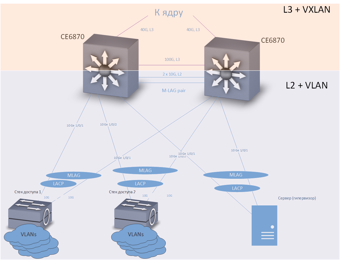
At home, we solved this problem as follows: we built a basic L3 network with full redundancy, using the IS-IS protocol . On top of the core, an overlay network based on EVPN / VXLAN technology was built using the MP-BGP routing protocol . To speed up the convergence of routing protocols, they applied BFD technology.
Network structure
On testing, such a scheme proved to be excellent - if any channel or switch is disconnected, the convergence time is no more than 0.1-0.2 s, the minimum packets are lost (often none), TCP sessions do not break, telephone conversations are not interrupted.
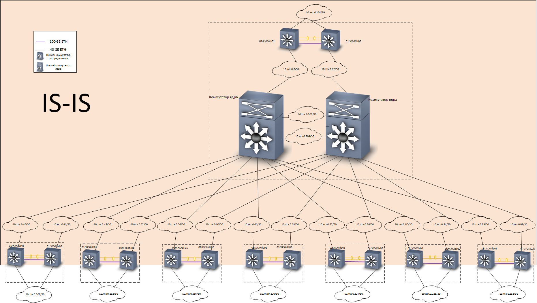
Underlay layer - routing
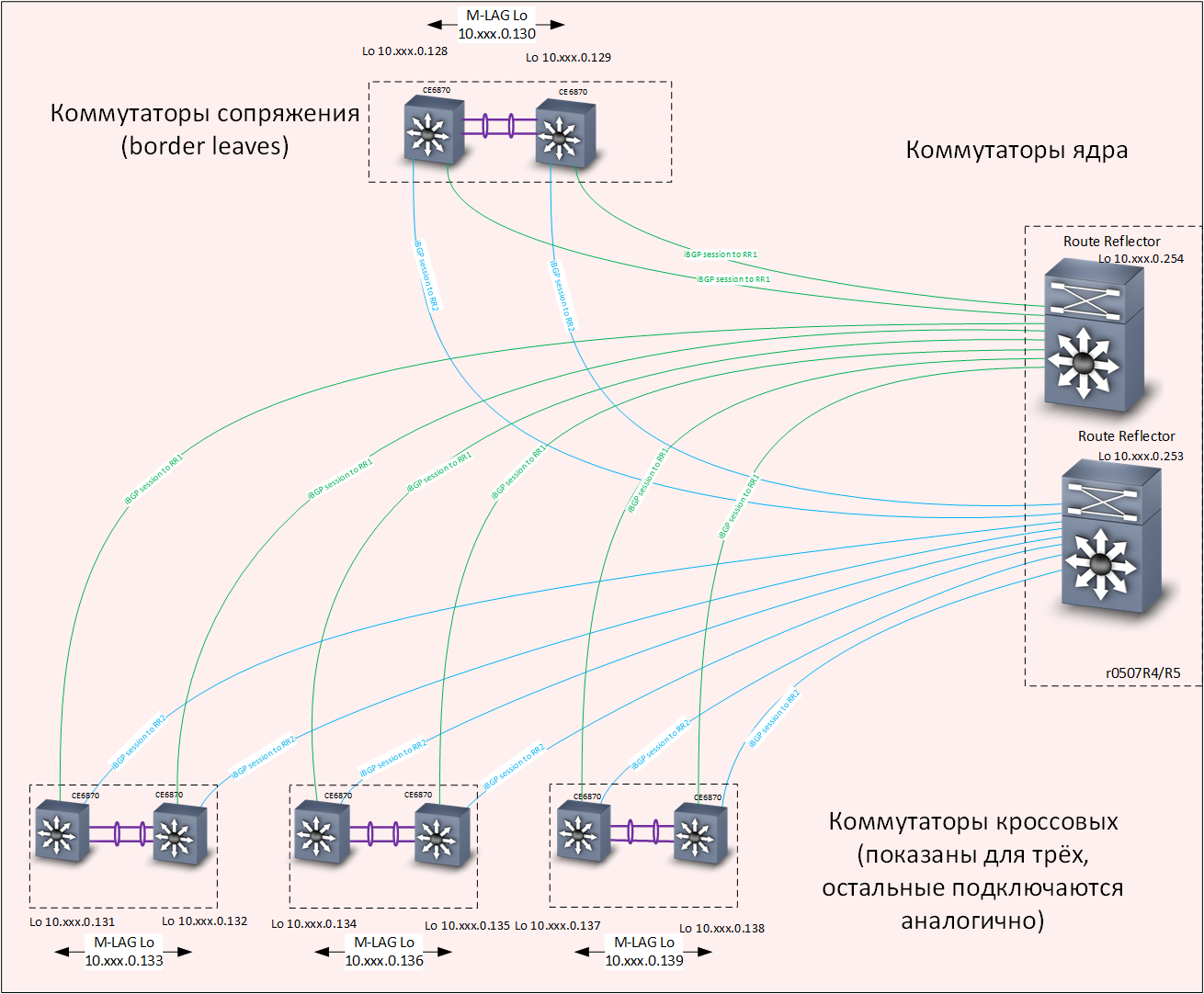
Overlay level - routing
Huawei CE6870 switches with VXLAN licenses were used as distribution switches. This device has an optimal combination of price / quality, allows you to connect subscribers at a speed of 10 Gb / s, and connect to the trunk at speeds of 40-100 Gb / s, depending on the used transceivers.
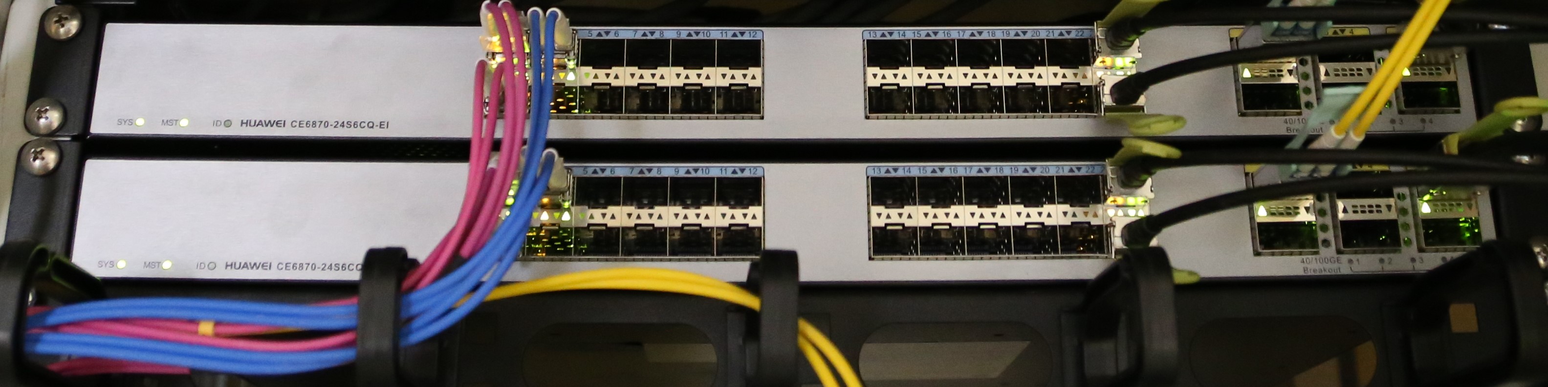
Switches Huawei CE6870
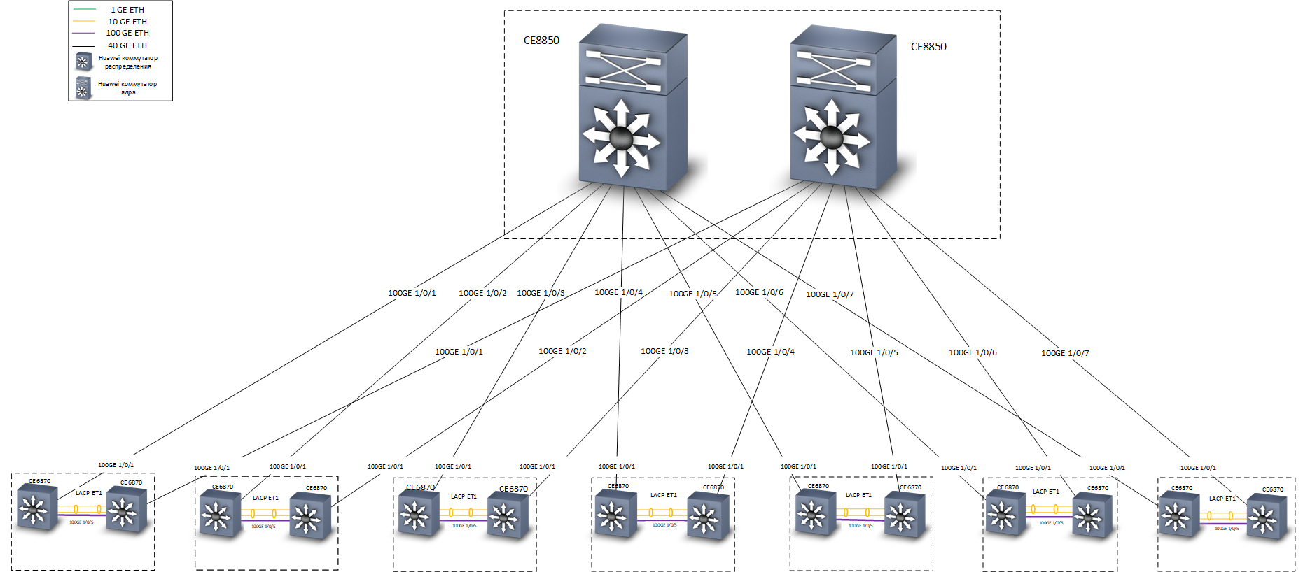
Huawei CE8850 switches were used as the core switches. From the task - quickly and reliably transmit traffic. No devices other than distribution switches are connected to them, they know nothing about VXLAN, so a model with 32 ports 40/100 Gbit / s was chosen, with a basic license providing L3 routing and support for IS-IS and MP-BGP protocols .

The lowest - Huawei CE8850 kernel switch
At the design stage, a team discussion broke out about the technologies with which you can implement a fault-tolerant connection to the core network nodes. Our Moscow office is located in three buildings, we have 7 cross-premises, each of which was equipped with two distribution switches Huawei CE6870 (in a few cross-rooms only access switches were installed). In developing the network concept, two backup options were considered:
- Consolidation of distribution switches in a fault-tolerant stack in each cross-connected room. Pros: simplicity and ease of customization. Minuses: higher probability of failure of the entire stack when the manifestation of errors in the firmware of network devices ("memory leaks" and the like).
- Apply M-LAG and Anycast gateway technologies to connect devices to distribution switches.
As a result, we stopped at the second version. It is somewhat more complicated to set up, but in practice it showed its efficiency and high reliability.
Consider first connecting the end devices to distribution switches:
Cross
An access switch, server, or any other device requiring a fault-tolerant connection is included in two distribution switches. M-LAG technology provides redundancy on the data link layer. It is assumed that the two distribution switches look like one device to the connected equipment. Load redundancy and balancing is done via the LACP protocol.
Anycast gateway technology provides redundancy at the network level. A sufficiently large number of VRFs are configured on each distribution switch (each VRF is designed for its own purposes — separately for “ordinary” users, separately — for telephony, separately — for different test environments and development environments, etc.), and in each VRF is configured with multiple VLANs. In our network, distribution switches are the default gateways for all devices connected to them. The IP addresses corresponding to the VLAN interfaces are the same for both distribution switches. Traffic is routed through the nearest switch.
Now consider connecting distribution switches to the kernel:
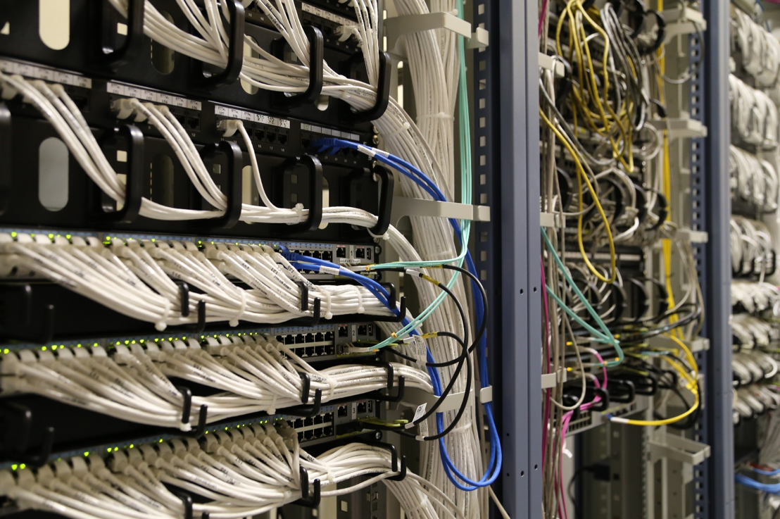
Fault tolerance is provided at the network level, according to the IS-IS protocol. Please note that there is a separate L3 communication line between the switches, at a speed of 100G. Physically, this line of communication is a Direct Access cable, it can be seen on the right in the photo of Huawei CE6870 switches.
An alternative would be to organize an “honest” fully connected topology “double star”, but, as mentioned above, we have 7 cross rooms in three buildings. Accordingly, if we chose the “double star” topology, then we would need exactly twice as many “long-range” 40G transceivers. The savings here are very substantial.
I need to say a few words about how VXLAN and Anycast gateway technologies work together. VXLAN, if you don’t go into details, is a tunnel for transporting Ethernet frames within UDP packets. The destination IP addresses of the VXLAN tunnel are loopback interfaces of distribution switches. Each switch has two switches with the same addresses of the loopback interfaces; accordingly, a packet can arrive at any of them, and an Ethernet frame can be extracted from it.
If the switch knows the target MAC address of the extracted frame, the frame will be correctly delivered to its destination. For the fact that both distribution switches installed in one cross have up-to-date information on all MAC addresses "arriving" from access switches, the M-LAG mechanism provides for synchronization of MAC address tables (as well as ARP tables) on both switches M-LAG-pairs.
Traffic balancing is achieved due to the presence of several routes in the underlay network to the loopback interfaces of distribution switches.
Instead of conclusion
As mentioned above, on tests and in operation, the network showed high reliability (recovery time with typical failures of no more than hundreds of milliseconds) and good performance — each cross connects to the core with two 40 Gbit / s channels. Access switches in our network are stacked and connected to distribution switches via LACP / M-LAG by two channels of 10 Gbit / s. In the stack, there are usually 5 switches with 48 ports each, up to 10 access stacks are connected to the distribution in each cross. Thus, the highway provides about 30 Mbit / s per user, even at the maximum theoretical load, which at the time of this writing is sufficient for all of our practical applications.
The network allows you to easily pair any arbitrary connected devices with both L2 and L3, providing complete isolation of traffic (which the information security service likes) and the failure domains (which the operation service likes).
In the next part we will describe how we migrated to the new network. Stay tuned!
Maxim Klochkov
Senior Consultant, Network Audit and Complex Projects Group
Network Solution Center
Jet Infosystems
Source: https://habr.com/ru/post/455397/
All Articles