Stable current source from 5 μA to 20 mA

A source of stable current was needed by the author for debugging circuits on bipolar transistors, which, as is well known, are controlled by current. An important requirement for it is the isolation of the common wire of the device from the common wire of the device being debugged, so the power source had to be taken offline. The built-in four-digit microammeter with automatic switching of the limits allows to slightly reduce the amount of equipment simultaneously placed on the experimenter’s table.
The idea of the scheme is taken from here . Actually the source of a stable current is arranged like this:
')
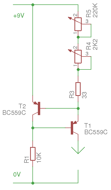
The resistance of the resistor R1 is uncritical, you only need the base current of the transistor T1 to fully open it. The current transfer ratio of the transistor BC559C is about 500, the upper limit for adjusting the current at the source is 20 mA, which means 200 μA through the base is more than enough. A 10 kΩ resistor will provide about 1 mA at 10 V, in principle, you can even increase it to 50 kΩ.
The T1 and T2 transistors should be the same, but at high currents, the T1 parameters will still “float” a bit because of the low heat.
The current supplied by the device to the external circuit is determined by the total resistance of the resistors R3 - R5. Their functions: R3 - current limiting in case both variable resistors are turned “to zero”, R4 - precise current regulation, R5 - coarse. The current is calculated by the formula I = 0.7 / (R3 + R4 + R5), so, for example, if the resistor R3 is taken as resistance of 27 Ohms, the upper limit of the current adjustment will be 0.7 / 27 = 25.9 mA. In practice, it turned out 21.6 mA, since the voltage drop on the T2 transistor turned out to be less - about 0.6 V.
Complete device layout:

“Krona” feeds a source of stable current, two AAA elements - a four-digit microammeter. Therefore, the power switch is taken with two normally open contact groups. Switch S1 allows you to disable the upper terminal and short-circuit the current source to configure it in advance before connecting to the circuit being debugged.
In practice, the parameters turned out to be the following: the maximum current is 21.6 mA, the maximum current with a “rough” regulator turned out “to zero” is 0.3 mA, and the minimum is 4.7 μA. True, the built-in microammeter less than 10 μA does not show, so external may sometimes be required. Exposed current remains almost unchanged when the voltage on the external circuit varies from 0 to 8 V.
The microammeter is made of a multimeter with automatic switching of the limits of JT-033A from SHENZHEN JINGTENGWEI INDUSTRY CO., LTD: the mode switch is removed, jumpers are soldered in its place, forcing it to always work in current measurement mode.
The layout of the components in the case is as follows:

Jim made a circuit simulation in Falstad, the author reworked it a bit to display more parameters, it turned out:
$ 1 0.000005 7.619785657297057 65 5 50 t 224 240 176 240 0 -1 0.6771607865907852 -0.5873050244463638 500 t 256 272 304 272 0 -1 1.8738439949380101 -0.6771607865907852 500 r 176 304 176 400 0 10000 v 80 288 80 192 0 0 40 9 0 0 0.5 w 176 304 176 272 3 w 176 272 176 256 0 w 176 224 176 32 1 w 176 32 80 32 0 w 80 32 80 192 0 w 80 288 80 400 0 w 80 400 176 400 3 w 176 400 304 400 0 w 304 336 304 288 3 w 304 240 224 240 1 174 304 128 352 48 0 5000 0.9950000000000001 Resistance w 176 32 304 32 2 w 304 256 304 240 0 w 304 240 304 208 2 w 304 128 336 128 0 w 352 80 352 128 0 w 352 128 336 128 0 w 256 272 176 272 1 w 304 128 304 208 1 r 304 336 304 400 0 250 Simulation result:
And here is the result of a simulation with the resistor R1 resistance of 100 kΩ:

Source: https://habr.com/ru/post/455371/
All Articles