How to 4 times increase the operating time of devices with autonomous power
The story of how we optimized the power circuit of autonomous sensors for collecting, processing and transmitting information. We have achieved a reduction in the cost of electronics, the weight of the sensor and slightly increased its overall dimensions.

The article describes the evolution of the power supply circuit of autonomous sensors for collecting and processing information. I will try to briefly describe all stages of the improvement scheme. I will begin the story with the development of a prototype that meets all the requirements except the main one. I'll tell you about trying to bring the work scheme to the requirements with minimal effort, simply by increasing the number of batteries. I will describe the search and analysis of the causes of the discrepancy between the parameters of the scheme. In the final part I will give an optimized scheme and comparison before and after.
I hope my experience will come in handy when designing self-powered devices.
I work for Uniscan Research. We make high-tech devices serial product. This article describes the process of optimizing the power supply system for autonomous devices developed in one of our projects.
For one of the large projects, we needed to develop a system for collecting and processing information, consisting of small sensors with autonomous power, transmitting the collected data to the operator’s console via radio.
The key requirements for the system being developed are minimum weight, minimum element sizes, simple and fast installation on the ground, high speed and reliability of data delivery, available batteries and the possibility of their replacement.
Initial Power Requirements
One of the main requirements is the battery life in the area of 240 hours, so that the need to replace the batteries arises as rarely as possible.
A rough estimate of the power consumption was carried out on the basis of data on the consumption of other autonomous devices. A device working on a single AA battery for 240 hours seemed completely realizable.
I conducted the initial assessment as follows:
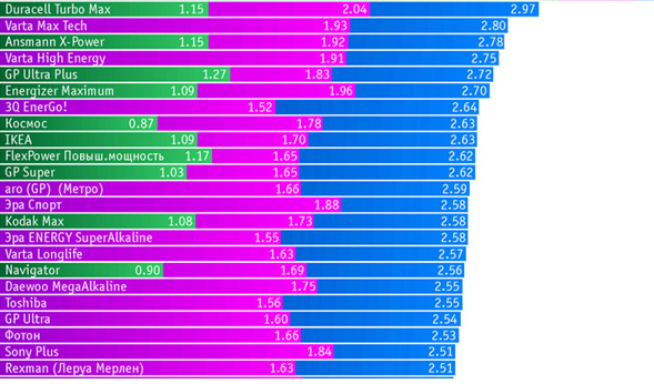
- Estimate the capacity of commercial "batteries". We use data from bona fide researchers. The graphs show the effective capacity of the batteries when discharged by different currents. The blue speakers are the battery capacity at minimum discharge, in tests performed, with a current of 200 mA. The average battery capacity is estimated at 2500 mAh, for a discharge current of 200 mA.
- We estimate the power consumption of a similar device. There is a device that consumes about 1 mA of 12V, which is 12mW.
- We calculate the battery life of the device. The “battery” capacity was estimated as 2500 mAh, the rated voltage is 1.5V, thus, the operating time at a consumption of 12 mW can be calculated:
Current Consumption = (Power Consumption) / (Rated Voltage) = 12mW / 1.5V = 8 mA
Battery life = (Capacity, mA * h) / (current consumption mA) = 2500 mA / 8mA = 312 hours.
At least 300 hours. Like this.
The specificity of the application of the system is such that commercial AA-size alkaline batteries, “finger batteries,” were best suited for the role of the main battery. One of the main reasons for choosing this battery can be bought at any store in the world.
Development of a prototype power supply sensor
It is impossible to power the sensor circuit directly from the battery. It is necessary to develop a power supply circuit for generating the necessary voltages for the electronics.
To do this, we need to determine the input and output voltages of the circuit and the required power (current consumption).
Determining output voltages is simple:
- A 3.3V voltage is required to power the controller and the entire periphery of the sensor.
- To power the RF amplifier radio modem - 3.6V.
We can also estimate the expected current consumption:
- For a common power bus 3.3V, in standby mode, about 4-6 mA.
Determining the voltage at the input of the circuit is also not difficult. The main battery is an alkaline "finger-type battery":
- Input voltage from 1 to 1.5V.
It seems that everything turned out, but there are nuances:
- The current consumption of the radio modem during transmission is high. The subtracted “battery” is not able to instantly give off significant power. The voltage on it will “drain”, due to the large internal resistance, the device will turn off. You need a drive that slowly stores energy until it is transmitted over the air. And during transmission provides the necessary power.
- The size of AA batteries is used not only for alkaline "batteries". In the same standard size, nickel-metal hydride batteries, lithium-thionyl-chloride batteries Saft are produced. And even Li-Ion batteries size 14500, which corresponds to the size of AA. Such diversity increases the input voltage range. A fully charged Li-Ion battery has an output voltage up to 4.2V.
In order for the power supply system to be quite universal, it must remain operable in the input voltage range from 1 to 4.2V.
A small nuance brings serious complications to the scheme. The input voltage can be either lower than the output voltage, or higher, the circuit should be able to increase the voltage and lower it. I did not succeed in finding a suitable microcircuit that could simultaneously lower and increase the voltage, due to the very low input voltage of 1 V. I developed a circuit that increased the input voltage to an intermediate level of 5V and then reduced it to the required voltage of 3.3V.

The 3.3V supply voltage feeds all circuit elements and a dedicated converter that charges the supercapacitor to 4V. The capacitor provides energy storage and provides power to the radio transmitter using a buck-boost converter.
With such a power scheme, prototype sensors were assembled. The programmer has developed software for sensors. After a long debugging and a number of improvements, we got the first samples of devices. Began testing.
The time of continuous operation of the device from one AA “DuraCell TurboMAX” battery was 33 hours. From "super batteries", lithium "Energizer Ultimate Lithium" - 55 hours. For a regular alkaline battery, the lifetime is 10 times less than the required one.
Switch to two AA batteries
Continuous battery life needed to be increased. The easiest way is to increase the number of batteries. Requirements for weight and dimensions were made tough, so it was only possible to increase the number of elements to 2 pcs.
The increase in the number of batteries has changed the requirements for the power scheme. Batteries are connected in series, which means that the input voltage is doubled. It was 1B - 4.2V, it became 2B - 8.4V.
The maximum allowable voltage at the input of the developed power supply circuit is determined by the input converter and is 5.5V. This means that the power circuit is not suitable for the sensor or it is necessary to limit the range of applicable batteries. We went the second way - refused Li-Ion batteries and lithium-thionyl-chloride batteries Saft. Quickly rework the power scheme was not possible.
Measurement of sensor operation time from two batteries without changing the power circuit showed the following results:
- From 2 batteries “Energizer Ultimate Lithium” the same devices worked for about 120 hours.
- From 2 AA batteries “DuraCell TurboMAX” the operating time was about 70 hours.
The time of continuous work increased by 2 times, but still was unsatisfactory.
The next step to increase battery life was to optimize the efficiency of the power supply circuit.
Measurement of the efficiency of the inverters and the overall efficiency of the power supply
As part of the optimization of the power supply circuit, I conducted a series of studies of converters on which the circuit was built.
Input boost converter
The booster converter is built on the LTC3422EDD Linear microcircuit; in the initial version, the converter formed a voltage of 5V at the output:
For the converter based on LTC3422EDD, I measured the efficiency dependencies on the load current of the converter at the converter supply voltage 1.5V and 3.0V, for output voltages 3.3V and 5V:

The dependence of the converter efficiency on the input voltage at constant load, P = 50mW, characteristic of the operating mode of the sensor, at the output voltage of the 3.3V and 5V converter:

The study of the efficiency of a step-up converter shows that using two batteries and reducing the output voltage of the converter to 3.3V increases the efficiency of the converter by up to 20% for a typical power consumption of 50 mW. When using 1 battery and an output voltage of 5V, the efficiency is about 70% (red graph in Fig. 1., the output current is from 5 to 14 mA). When using 2 batteries and reducing the output voltage to 3.3V, the efficiency reaches 89% (blue graph in Fig. 2., the output current is from 5 to 19 mA).
You can also expect improved efficiency in the entire range of battery performance. For one battery, the operating voltage range is 0.9-1.5V. The best efficiency for a fresh battery, according to the schedule fig. 3, is 69%. Whereas the worst efficiency value, when using two discharged batteries with a residual voltage of 1.1V + 1.1V = 2.2V, will make according to the diagram in fig. 3 about 79%. For a set of fresh batteries, the expected efficiency is up to 84%.
Increases the load capacity of the converter when using 2 batteries. For one battery, the efficiency drops significantly when the current consumption is more than 20 mA, whereas when using 2 batteries, the converter retains a high efficiency value when the load current is more than 100 mA.
Reducing the output voltage of the boost converter to 3.3V increases the time of continuous operation by 20%, by increasing the efficiency of the converter.
Reducing the output voltage also increases the load capacity of the converter.
Also, I estimated the dependence of the efficiency on the load current of the converter while reducing the output voltage to 3.3V:

When using 2 batteries and reducing the output voltage to 3.3V, not only the efficiency is increased, but also the load capacity of the converter increases by more than 2 times.
3.3V down converter
The downconverter is built on an LTC3406 Linear microcircuit. In the initial version, the converter formed a 3.3V voltage at the output from the intermediate voltage of 5V:

For the converter based on LTC3406 I measured the dependence of the efficiency on the load current
at an input voltage of 5V.

Evaluation of the efficiency of the converter, which forms the supply voltage of 3.3V, showed a value of about 70% with a consumption current of 50 mW typical for the main operation mode.
Evaluation of the overall efficiency of the power circuit
For the initial execution of the power supply circuit, the efficiency rating is obtained by multiplying the efficiency of the boost converter and the efficiency of the 3.3 V converter.

If you use 2 batteries, reduce the output voltage of the boost converter to 3.3V and exclude the converter that formed 3.3V before this, the efficiency of the power supply circuit will be equal to the efficiency of the boost converter:

** We get the necessary actions for optimization of the scheme:
- Use 2 batteries.
- Reconfigure boost converter to output voltage 3.3V.
- Delete the down converter. **
Optimized power scheme
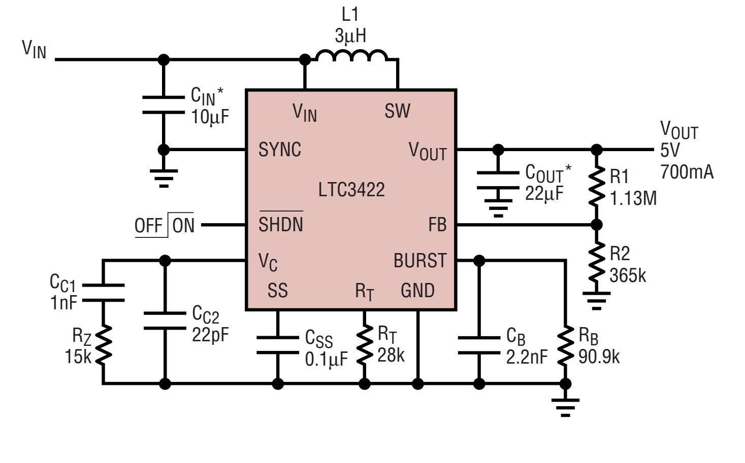
According to the results of research, I developed a simplified, but more optimal sensor supply circuit:

Two batteries, connected in series, are connected to a step-up converter, which forms a 3.3V supply voltage to power the entire electronics of the device. A specialized converter charges the supercapacitor, from which the RF amplifier is powered during transmission over the radio channel through the buck-boost converter.
The time of continuous operation of the device increased by more than 2.5 times and reached an acceptable battery life of 120 hours from the usual "finger batteries." When using Energizer Ultimate Lithium lithium batteries, battery life has reached 200 hours.
Optimization results
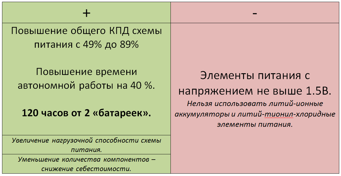
In my experience, the power supply circuit of autonomously working devices is always a compromise between the required functionality and the battery life. I managed to increase the battery life by 4 times through the rejection of versatility. We have excluded expensive and rare batteries. At the same time, we retained a requirement that was considered important - “out of the store” batteries are used. To get more battery life, you can use more rare and expensive, but still easily accessible, commercial batteries.
The development of unique devices is always an assessment of many implementation options. To find a compromise between the full functionality, cost, reliability and complexity of technical implementation is the main task of the engineer.
')
Source: https://habr.com/ru/post/455292/
All Articles