Doppler speed meter
The principles of frequency modulated radar with a constant carrier frequency are used in interferometry to measure the distance to objects and their speed. This is achieved by transmitting the FM signal and measuring the difference in frequency between the delayed received and transmitted signals. The focus of this project was on the development and implementation of a power splitter and mixer circuit. The radar architecture is shown below.
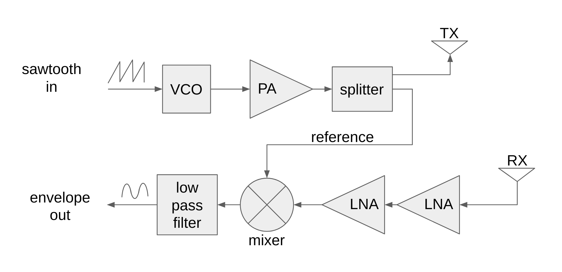
Doppler radar architecture
The splitter is a directional coupler with connected copper microstrip lines. When an electric current passes through the microstrip line of a printed circuit board, electric and magnetic fields appear between the microstrip and ground planes on the opposite side of the dielectric substrate. In the center of the microstrip, the electric field is uniform, but towards the edge of the microstrip line, it flows outward, propagating through its boundary. This effect allows to combine the energy of two microstrip lines physically located close to each other. In the case of power couplers and splitters, this is very advantageous, and by adjusting the distance between them, you can adjust the amount of energy passing between them to the desired value.
')
Using Qucs - the universal circuit simulator, the authors calculated the dimensions for the microstrip connector and the microstrips themselves on the printed circuit board. Some of them served as transformers wave resistance of 50 Ohms.

The vertical axis is the attenuation value in dB, and the horizontal axis is the frequency in Hz.
The blue curve (S11) is the power reflected by the connector that is minimized around the 2.4 GHz base frequency radar. The red curve (S13) is the power transmitted through the coupler, -12 dB corresponds to about 6% of the power. Almost all power is transmitted as shown by the pink curve (S12).
The authors fabricated a prototype on a substrate of the FR-1 microwave fiberglass textolite and measured the scattering parameters using a network analyzer. The prototype is shown below.
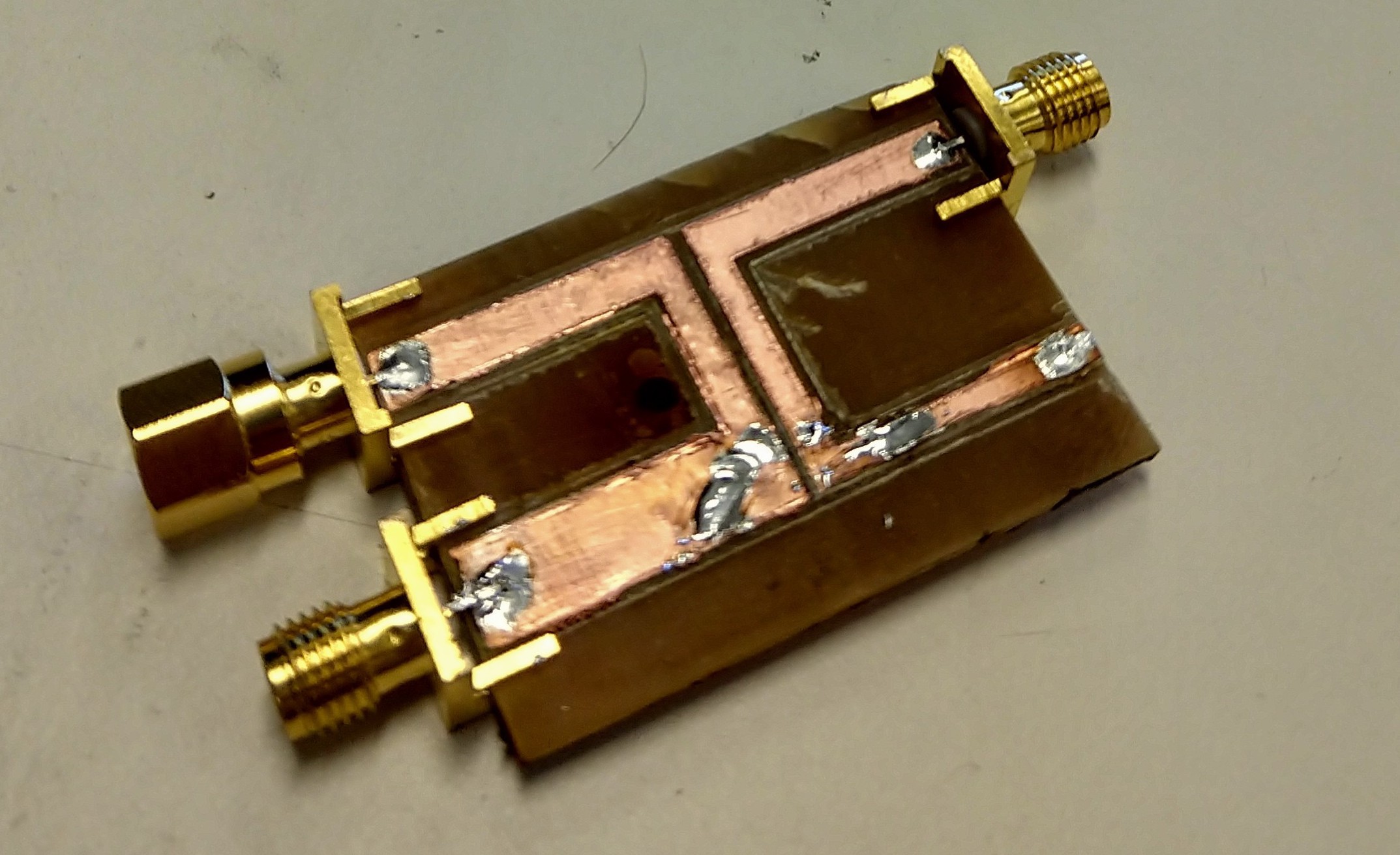
Splitter Prototype
The prototype was not exactly tuned to the 2.4 GHz frequency and had a fairly high reflection coefficient (-10 dB), but the power coupling (-17 dB) and transmission (-7 dB) were very decent. Part of the loss was obviously determined by a weak connection between the SMA and PCB connectors.
The mixer circuit consists of a summing mixer and a half-wave rectifier RC circuit for extracting an envelope. The summing mixer is a Wilkinson power adder that has excellent port isolation, the two input ports (on the right in the figure) are divided into half-waves (1.2 GHz) through an adder and a resistor.
The prototype shown below was also made from the same microwave fiberglass FR-1. And it somehow turned out to be much more aesthetic than the above splitter, the signal attenuation reached -25 dB at 2.4 GHz, the maximum attenuation value of about -35 dB was observed closer to 3.5 GHz, which indicates that the loop length was physically too small for the properties of our prototype, it turned out not quite equal to a quarter of the wavelength at 2.4 GHz.
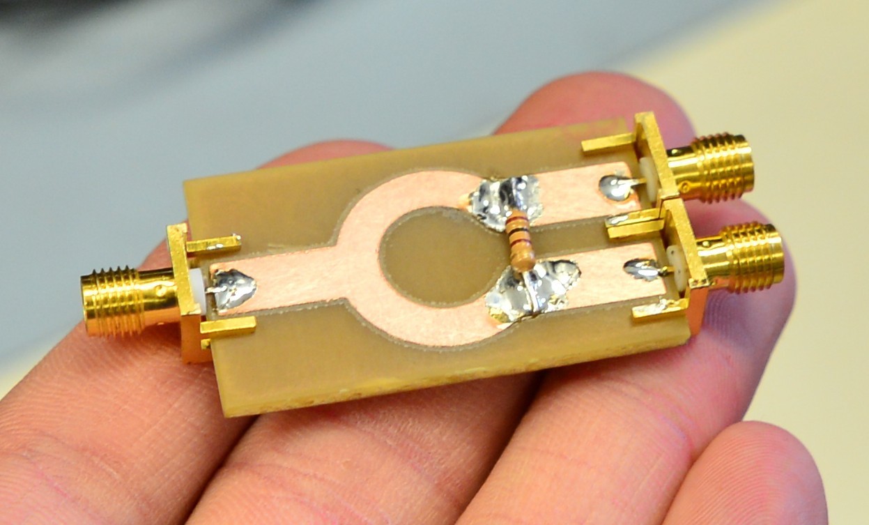
Mixer prototype
After testing the prototypes, the authors developed a board that combines all the modules shown above in the block diagram. The board was etched on a FR-4 fiberglass substrate, which has about the same relative dielectric constant as FR-1.
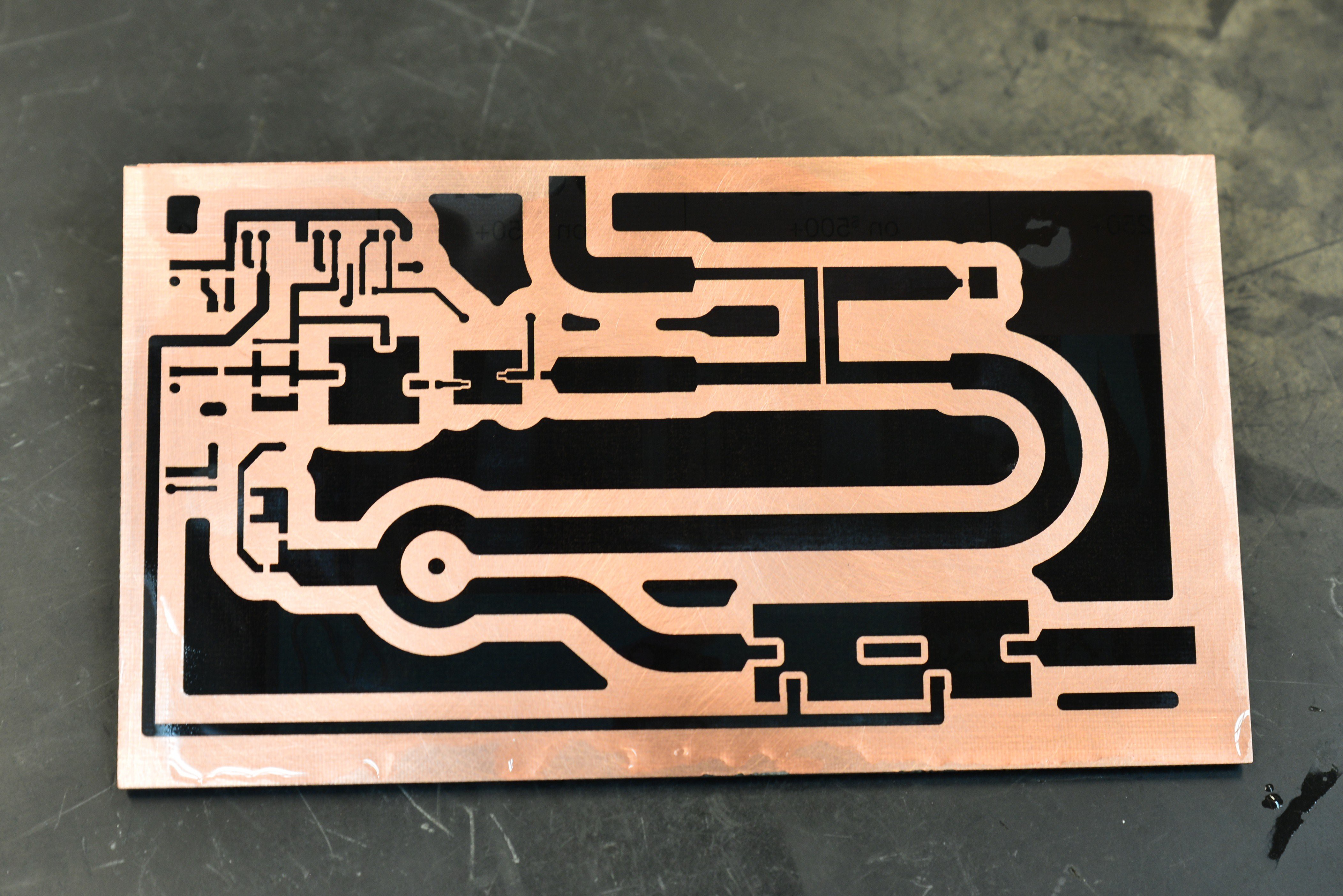
Board image after etching with toner
Hot air to remove toner
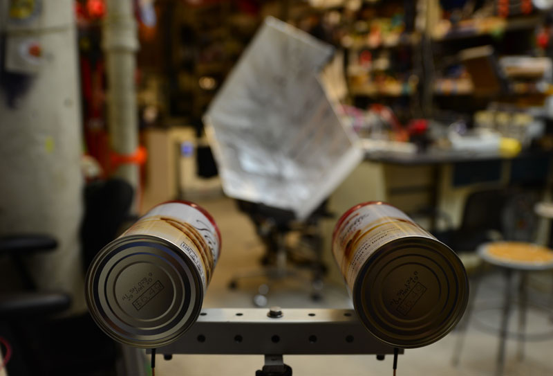
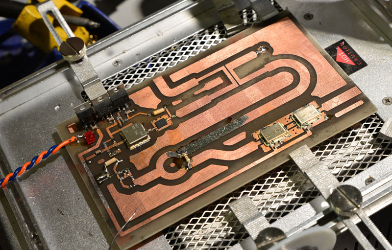
When the authors finally finished mounting the board and connected it to a function generator, which supplies voltage to the VCO and an oscilloscope that measures the voltage at the mixer output, they could not measure any beat tone, even with a highly reflective metal corner "cube" (shown below).
Angular "cube" to reflect the wave
In the end, after checking almost all possible modulation frequencies and placing the board in the shielding box, it was found that the movement of the reflector led to a beating with a frequency directly proportional to the speed of movement of the reflector.
This result confirmed that the power divider and mixer worked, so the Doppler radar was designed. A moving reflector creates a Doppler shift, so that the received signal has a different frequency from the transmitted signal, which the authors were able to measure with a mixer.
Source: https://habr.com/ru/post/455216/
All Articles