Training Cisco 200-125 CCNA v3.0. Day 9. The physical world of switches. Part 1
In the past video tutorial, we talked about setting up switches, and now we will look at how they interact with other devices and how they are connected in practice. We will not waste time and immediately move on to the topic of today's lesson. First of all, I want to talk about topology: we have two different topologies - physical and logical.

The difference between them is very simple, and there is one important thing you need to know about before diving into the real world of networking. Let me take a pen and draw a route from Dubai to New York on this map. What I drew is not a land trip, but an air flight. Logically, you simply travel from Dubai to New York, but physically everything is not so simple - you must first go to the airport and get a ticket. You can book it online or buy it at the box office, you can use a credit card or cash to buy it, you can go to the airport by taxi or by your own car and leave it at the airport. Then your ticket must be checked, you must go through customs, that is, you have to do a lot of different things before you get on board the aircraft. After that, you will fly to New York, and a similar procedure will be repeated there - going through control, getting luggage, you can hire a taxi or ask friends to pick you up from the airport to finally get to your destination. This is how you can imagine the difference between the logical and physical topology of the network.
')
If you look at the next picture, you can see how people imagine the network.
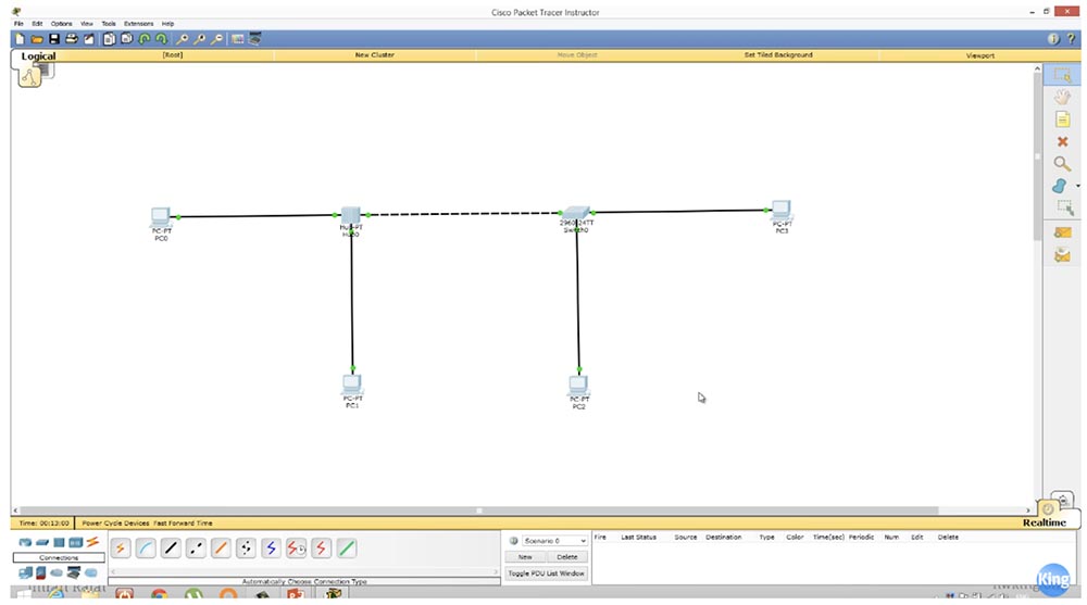
The computer is connected to a hub, a hub with a switch, a switch with another computer. To the right, 2 computers are connected to the switch, and to the left, two computers are connected to the hub, and the hub and the switch are connected to each other. This is a logical network topology.
If you use the Cisco Packet Tracer program shown in the picture, then at the top left you will have a Logical button, clicking on which you can see the logical topology of your network. If I click on the Physical button next to it, I will see the physical network topology. To do this, from the “Physical Device Location” menu, I select the Rack option - “Rack”, and a Cisco rack will appear in front of me, on which my switch and hub are located.

I want to show you a picture of a real stand, which I just took from the Internet, so I don’t have any rights to it. Above you see a link to the site from where I took this picture.
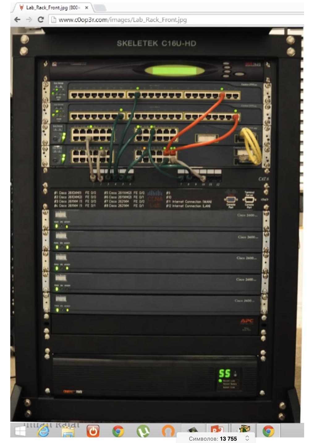
Several Cisco devices are mounted and secured to such a rack, which are then connected to each other to create a network of the required configuration. This is what the physical network topology looks like, and you can add the devices you need to any free rack compartment, grouping them by type - a switch over a switch, a hub next to the hub, etc. Then you can build your network by simply connecting devices in a rack with cables. In our illustration, the green cable connects the hub to PC0 and PC1, and the orange cable connects the hub to one of the switch ports. Another green cable connects the switch to the third PC2 computer. Thus, many devices are attached to the switch.
This is the physical network topology. As soon as you add new devices to the logical network topology, they will immediately appear on the Physical tab of the program (physical devices) already installed on the Cisco rack.

I want you to understand the difference between the physical and logical network topology, because most often when a network problem occurs, you have such a connection, as shown in the logical topology diagram. But if you come to a new place of work, then you do not have a logical topology to which you can refer. You work with the physical network topology, you go to the server and look at all these devices installed in the rack. In order to make a network of them, you must use different protocols, for example, VTP, which we will talk about in one of the following video tutorials. You use these protocols to determine which devices are connected to which ports. You can determine this physically and try to create a logical topology. This is basically what I wanted to say before going directly to the topic of the lesson.
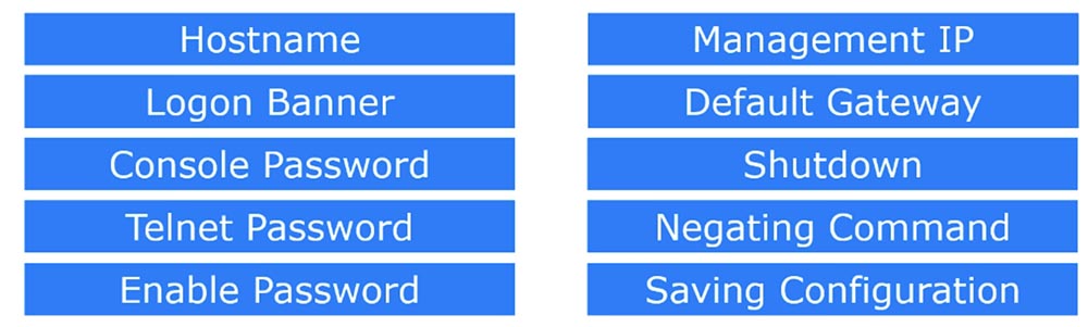
Let's do what we learned in the previous lesson, so I’ll skim through these 10 commands, or 10 basic switch configuration settings that we need to perform for any new device.
In the case of the above example of a logical network topology, you must configure the hub and the switch so that they can interact with our 4 computers. Let's start with the switch, to do this, click on it and enter the command line terminal.
First, configure the host name and name it SW1. Next, we must create a welcome banner on which we will write the following phrase: “Do not enter! This is a dangerous switch! For this you will be held accountable! ”

After the previous lesson, many people ask me why it is necessary to use an ampersand in the parameters of the banner line. You can not use &, use any other character enclosed in quotes. The main rule when creating a banner is not to use this symbol, located in quotation marks, as the initial symbol for the banner text. If I type an ampersand in front of a lower field of asterisks, only the text above this ampersand will be saved, and the system will not remember anything that is below it. Thus, if I want to use the ampersand & in my text, I must specify another symbol as the end of the banner text, for example, the closing bracket “)”, placing it in quotes instead of &.
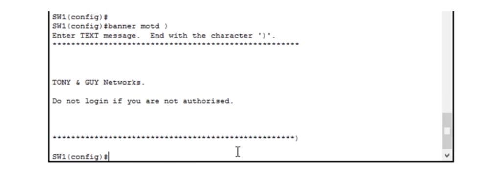
I will show it in the following example - set the “)” symbol, and then print the new text of the banner and finish the bottom row of asterisks with this closing bracket. If now I press "Enter", then the entire text of the banner in front of this bracket is automatically saved. Thus, if you want to end your message with a character, just do not start the message with that character.
So, we have created a welcome banner and now we can proceed to setting the password on the console. To do this, we type line con 0 in the command line, because the console is a communication line, and we have only one console port, so we denote the console by zero. I need to set a password on the console, so first I type the password console on the command line and assign the password to cisco, and in the next line I also need to type the word login. What does this login mean?
If I type the no login command now, many people will think that this will mean that there is no password on the console and they will be completely wrong! Login means just checking the password that the user enters. If I type no login, this check will not be performed, but this does not mean that we will not have a password. Login is like a door guard who asks anyone for a password, and if the password is wrong, they won't let it in. The lack of a login means that the “front door” of the console port will be open all the time for any traffic that passes through the port without requesting a password.
At any Cisco device, the console port is open by default, and anyone who connects to it can enter the device settings. Therefore, you need to configure the console port of the switch to prevent unauthorized access to it, that is, enter the login command.
Next, we need to set a password on Telnet. This is a virtual communication line, so I type line vty and since the numbering of these lines can be from 0 to 15, you can assign from 0 to 4 or from 0 to 15 such lines. I choose a value from 0 to 4. Next, we proceed in the same way as assigning a password to the console: I assign the password with the password telnet command and type login in the next line to ensure its verification. This means that anyone who tries to connect to the switch via Telnet will have to enter the correct password.
Next, I enter the do sh run command to look at the current device configuration. We have 16 Telnet lines, and for the lines of the first part of the range from 0 to 4 we have a telnet password and a login, and for the second part from 5 to 15 virtual lines there is only a login. The question arises why we have a separation of parameters for lines 0-4 and 5-15. If you think that this was due to the fact that I chose only four working lines, then this is not entirely wrong.

Now I will explain to you. In total, we have 16 virtual lines from 0 to 15, and for a Cisco switch, this means that 16 users can connect to it at the same time. If I enter the command line vty 0 15, it means that I assign a password to all 16 users.
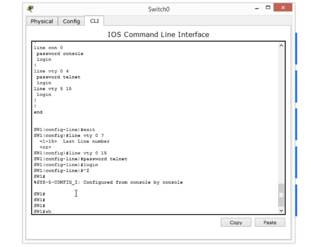
Now I will set a password and login for all 16 lines, and if you look at the configuration, you will see that now we have a password and login for both lines 0-4, and for lines 5-15.

What does it mean? As I said, 16 people will be able to connect to the switch using a telnet password, but the difference between 0-4 and 5-15 exists because most of the old Cisco switches have only 5 virtual lines from 0 to 4, and only the new models There are all 16 virtual lines 0-15. Therefore, Cisco believes that if you assign one password for all 16 lines, this can cause a problem. It may happen that you copy the configuration settings of one device and want to transfer it to other devices. But if you try to use the settings of a switch with 16 lines for a switch with 5 lines, the command will not be accepted. Therefore, Cisco advises - even if you use a switch with 16 virtual lines, use separate telnet password and login settings for lines 0–4 and lines 5–16, so that you do not have problems with older switch models, because the command for Line vty 0 4 is compatible with all models. The second part, line vty 0 15, applies only to new devices.
Thus, if you copy the settings of the new switch and want to apply them to the switch of the old model, you copy only the lines:
line vty 0 4
password telnet
login
Because the new switches will not understand the command for virtual lines 5-15, since they have only 5 lines. This is the reason for splitting the Telnet configuration into 2 parts.
If I want all Telnet lines to be accessible to any user, I use the commands:
line vty 0 15
no login
But this is not what we need - on the contrary, we want to protect the switch from unauthorized access. I'll show you how to do this in a minute, for now we have to configure the IP for our switch. To do this, I use the int vlan 1 command and add the IP address and subnet mask: add 10.1.1.1 255.255.255.0, capturing the changes with the no sh command (no shutdown).
Now let's go back to the logical topology diagram and configure the IP address using the first PC0 computer.

To do this, I enter the necessary parameters in the network settings window of the computer. We do not need to enter the default gateway parameters, since we have only 1 network.

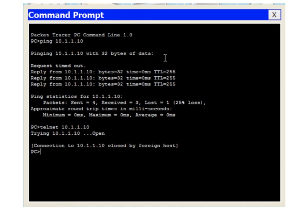
Next, I check if the switch is pinging, and make sure that everything works as it should. The fact that the first request generated a timeout error is explained by the fact that our computer accessed the device without knowing its MAC address, and subsequent requests were successful. So, I type ping 10.1.1.10 on the command line and I see the switch's welcome banner - this means that I connected to it.
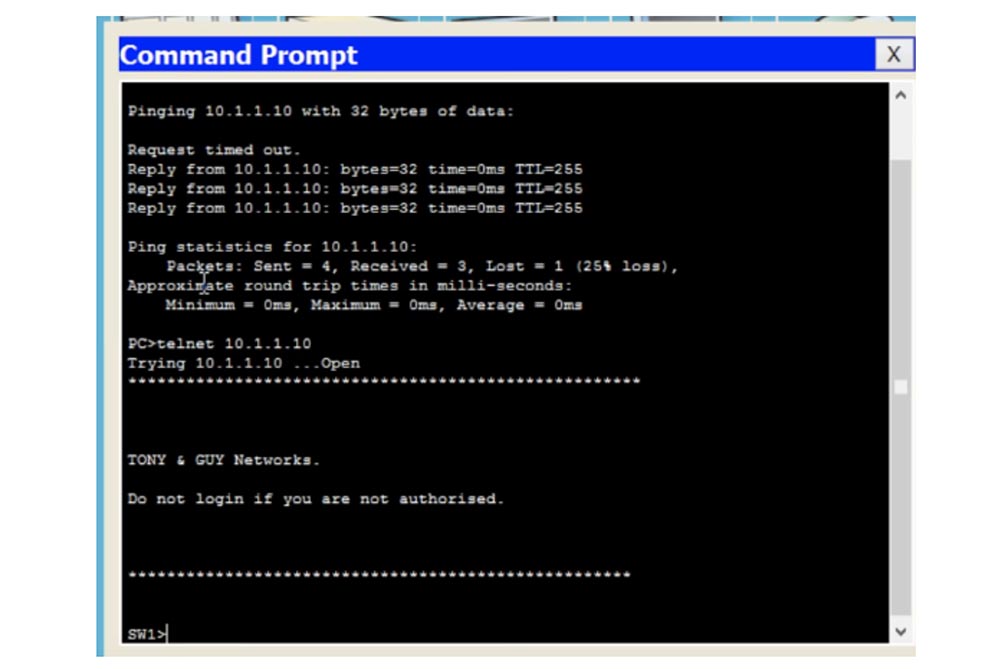
At the same time, the switch did not ask me for the password, because we left the Telnet line open - if you look at the configuration of the switch, you can see that for all lines from 0 to 15 the no login parameter is used, that is, anyone can connect to this switch via Telnet by simply using its IP address. If we now enter the command en (enable) to proceed to the installation of parameters, we will see the message% No password set - “Password not set”. This is one of Cisco's defense mechanisms, which requires the user to know the password, which allows configuration of the switch.
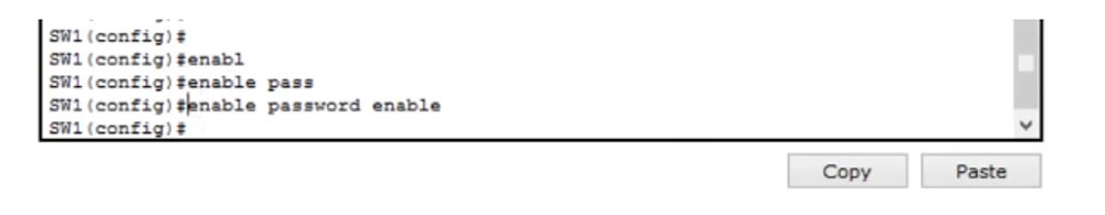
Therefore, we will go to the switch settings configuration window and use the command enable password enable, where the word enable will be our password. If we now enter this word in the terminal of the command line of the computer, we will get access to the switch settings, as evidenced by the appearance of the line SW1 #.

Thus, the security mechanism of Cisco makes it so that even if we do not activate the function of requesting the password enable password, it will still not be possible to access the settings of the switch.
Let me remind you that if you go to the Cisco Packet Tracer CLI tab, you can configure access via the console port. Thus, if you enter the device through the console port and do not provide password access, this will not be a problem, because you can activate the password request later when you configure the entire configuration. But if you enter a switch through a virtual telnet line, you will not get access to the settings unless you previously use the enable password command in the switch settings.
Since we do not want any Telnet user to have access to the settings, we must create a password. Suppose that we are going to use only 1 virtual line, so we enter the line vty 0 command. This will mean that the enable password parameter will be effective only for this single line. Then I enter the password check - the word login, in the next line I type password telnet and then exit.

For all the other 15 lines from 1 to 15, I will enter the no password and login parameter.
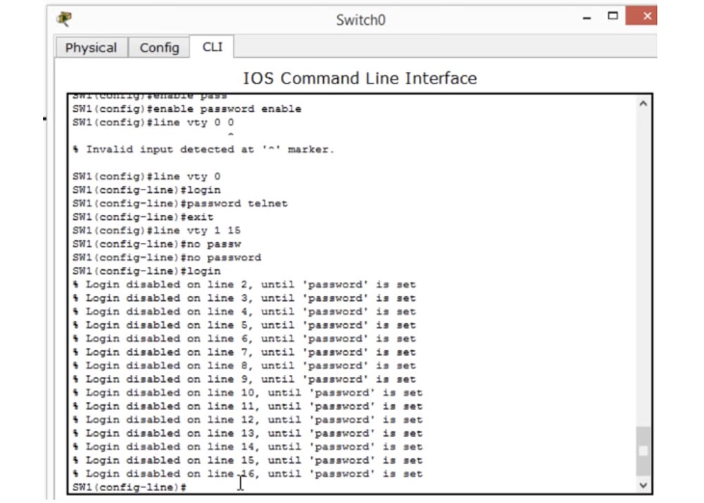
What does this mean? If I once again ask the system to show me the switch configuration with the command sh run, I will see the following: for the vty 0 line we have both a password and a login, and for lines 1-4 the login is activated, this is our “guard”, but the password is not set . This means that you can enter any password to enter the switch settings. At the same time, the screen displays messages in which it is written: “Logging in to the system via such a line is impossible until a password is set”.
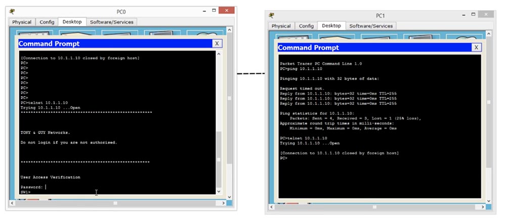
Now, if I go to the computer’s command line window and enter telnet 10.1.1.10, I’ll see a welcome banner asking me to enter a password. Let's go back to the logical topology and configure the network for the second computer - PC1, by entering the IP address 10.1.1.2 and the subnet mask 255.255.255.0. We will not touch the default gateway, because we have only one network, and then we will ping the switch to make sure that the connection is established.
If we now try to enter the switch settings from the second computer using the telnet 10.1.1.10 command, we will fail - the system will display a message that the connection is already in use by another host, since we have only one Telnet line number 0.
If you look at the command line terminal, we see that line 0 is already occupied by another device, and until I disconnect it, the new device will not be able to connect to the switch.
Now I will type the exit command to disconnect, re-enter the telnet 10.1.1.10 command in the command window of the second computer, and as you see, now he was able to connect to the switch. Now I will enter the word telnet as a password and I can enter the device settings.
If I want to have several devices connected to the switch at the same time, I have to configure it accordingly.
So, we set the parameters for Telnet password and Enable password, and now let's move on to managing IP addresses - IP management. If we want to communicate with a device belonging to another network, our switch should know how this can be done. Therefore, we return to the network settings of the computer and assign a default gateway, assigning our IP router address 10.1.1.100. With this address, our device will be able to communicate with devices outside the 10.1.1.2/24 network.
If our computer wants to connect to a device whose first three octets of the IP address are different than 10.1.1, the switch organizes this connection through the default gateway with the IP address 10.1.1.100. If you recall our example with hotels, you will immediately understand what this is about - if you want to go to another hotel, you will need to leave your hotel through the front door.
24:20 min
Thank you for staying with us. Do you like our articles? Want to see more interesting materials? Support us by placing an order or recommending to friends, 30% discount for Habr's users on a unique analogue of the entry-level servers that we invented for you: The whole truth about VPS (KVM) E5-2650 v4 (6 Cores) 10GB DDR4 240GB SSD 1Gbps from $ 20 or how to share the server? (Options are available with RAID1 and RAID10, up to 24 cores and up to 40GB DDR4).
Dell R730xd 2 times cheaper? Only we have 2 x Intel TetraDeca-Core Xeon 2x E5-2697v3 2.6GHz 14C 64GB DDR4 4x960GB SSD 1Gbps 100 TV from $ 199 in the Netherlands! Dell R420 - 2x E5-2430 2.2Ghz 6C 128GB DDR3 2x960GB SSD 1Gbps 100TB - from $ 99! Read about How to build an infrastructure building. class c using servers Dell R730xd E5-2650 v4 worth 9000 euros for a penny?
The difference between them is very simple, and there is one important thing you need to know about before diving into the real world of networking. Let me take a pen and draw a route from Dubai to New York on this map. What I drew is not a land trip, but an air flight. Logically, you simply travel from Dubai to New York, but physically everything is not so simple - you must first go to the airport and get a ticket. You can book it online or buy it at the box office, you can use a credit card or cash to buy it, you can go to the airport by taxi or by your own car and leave it at the airport. Then your ticket must be checked, you must go through customs, that is, you have to do a lot of different things before you get on board the aircraft. After that, you will fly to New York, and a similar procedure will be repeated there - going through control, getting luggage, you can hire a taxi or ask friends to pick you up from the airport to finally get to your destination. This is how you can imagine the difference between the logical and physical topology of the network.
')
If you look at the next picture, you can see how people imagine the network.
The computer is connected to a hub, a hub with a switch, a switch with another computer. To the right, 2 computers are connected to the switch, and to the left, two computers are connected to the hub, and the hub and the switch are connected to each other. This is a logical network topology.
If you use the Cisco Packet Tracer program shown in the picture, then at the top left you will have a Logical button, clicking on which you can see the logical topology of your network. If I click on the Physical button next to it, I will see the physical network topology. To do this, from the “Physical Device Location” menu, I select the Rack option - “Rack”, and a Cisco rack will appear in front of me, on which my switch and hub are located.
I want to show you a picture of a real stand, which I just took from the Internet, so I don’t have any rights to it. Above you see a link to the site from where I took this picture.
Several Cisco devices are mounted and secured to such a rack, which are then connected to each other to create a network of the required configuration. This is what the physical network topology looks like, and you can add the devices you need to any free rack compartment, grouping them by type - a switch over a switch, a hub next to the hub, etc. Then you can build your network by simply connecting devices in a rack with cables. In our illustration, the green cable connects the hub to PC0 and PC1, and the orange cable connects the hub to one of the switch ports. Another green cable connects the switch to the third PC2 computer. Thus, many devices are attached to the switch.
This is the physical network topology. As soon as you add new devices to the logical network topology, they will immediately appear on the Physical tab of the program (physical devices) already installed on the Cisco rack.
I want you to understand the difference between the physical and logical network topology, because most often when a network problem occurs, you have such a connection, as shown in the logical topology diagram. But if you come to a new place of work, then you do not have a logical topology to which you can refer. You work with the physical network topology, you go to the server and look at all these devices installed in the rack. In order to make a network of them, you must use different protocols, for example, VTP, which we will talk about in one of the following video tutorials. You use these protocols to determine which devices are connected to which ports. You can determine this physically and try to create a logical topology. This is basically what I wanted to say before going directly to the topic of the lesson.
Let's do what we learned in the previous lesson, so I’ll skim through these 10 commands, or 10 basic switch configuration settings that we need to perform for any new device.
In the case of the above example of a logical network topology, you must configure the hub and the switch so that they can interact with our 4 computers. Let's start with the switch, to do this, click on it and enter the command line terminal.
First, configure the host name and name it SW1. Next, we must create a welcome banner on which we will write the following phrase: “Do not enter! This is a dangerous switch! For this you will be held accountable! ”
After the previous lesson, many people ask me why it is necessary to use an ampersand in the parameters of the banner line. You can not use &, use any other character enclosed in quotes. The main rule when creating a banner is not to use this symbol, located in quotation marks, as the initial symbol for the banner text. If I type an ampersand in front of a lower field of asterisks, only the text above this ampersand will be saved, and the system will not remember anything that is below it. Thus, if I want to use the ampersand & in my text, I must specify another symbol as the end of the banner text, for example, the closing bracket “)”, placing it in quotes instead of &.
I will show it in the following example - set the “)” symbol, and then print the new text of the banner and finish the bottom row of asterisks with this closing bracket. If now I press "Enter", then the entire text of the banner in front of this bracket is automatically saved. Thus, if you want to end your message with a character, just do not start the message with that character.
So, we have created a welcome banner and now we can proceed to setting the password on the console. To do this, we type line con 0 in the command line, because the console is a communication line, and we have only one console port, so we denote the console by zero. I need to set a password on the console, so first I type the password console on the command line and assign the password to cisco, and in the next line I also need to type the word login. What does this login mean?
If I type the no login command now, many people will think that this will mean that there is no password on the console and they will be completely wrong! Login means just checking the password that the user enters. If I type no login, this check will not be performed, but this does not mean that we will not have a password. Login is like a door guard who asks anyone for a password, and if the password is wrong, they won't let it in. The lack of a login means that the “front door” of the console port will be open all the time for any traffic that passes through the port without requesting a password.
At any Cisco device, the console port is open by default, and anyone who connects to it can enter the device settings. Therefore, you need to configure the console port of the switch to prevent unauthorized access to it, that is, enter the login command.
Next, we need to set a password on Telnet. This is a virtual communication line, so I type line vty and since the numbering of these lines can be from 0 to 15, you can assign from 0 to 4 or from 0 to 15 such lines. I choose a value from 0 to 4. Next, we proceed in the same way as assigning a password to the console: I assign the password with the password telnet command and type login in the next line to ensure its verification. This means that anyone who tries to connect to the switch via Telnet will have to enter the correct password.
Next, I enter the do sh run command to look at the current device configuration. We have 16 Telnet lines, and for the lines of the first part of the range from 0 to 4 we have a telnet password and a login, and for the second part from 5 to 15 virtual lines there is only a login. The question arises why we have a separation of parameters for lines 0-4 and 5-15. If you think that this was due to the fact that I chose only four working lines, then this is not entirely wrong.
Now I will explain to you. In total, we have 16 virtual lines from 0 to 15, and for a Cisco switch, this means that 16 users can connect to it at the same time. If I enter the command line vty 0 15, it means that I assign a password to all 16 users.
Now I will set a password and login for all 16 lines, and if you look at the configuration, you will see that now we have a password and login for both lines 0-4, and for lines 5-15.
What does it mean? As I said, 16 people will be able to connect to the switch using a telnet password, but the difference between 0-4 and 5-15 exists because most of the old Cisco switches have only 5 virtual lines from 0 to 4, and only the new models There are all 16 virtual lines 0-15. Therefore, Cisco believes that if you assign one password for all 16 lines, this can cause a problem. It may happen that you copy the configuration settings of one device and want to transfer it to other devices. But if you try to use the settings of a switch with 16 lines for a switch with 5 lines, the command will not be accepted. Therefore, Cisco advises - even if you use a switch with 16 virtual lines, use separate telnet password and login settings for lines 0–4 and lines 5–16, so that you do not have problems with older switch models, because the command for Line vty 0 4 is compatible with all models. The second part, line vty 0 15, applies only to new devices.
Thus, if you copy the settings of the new switch and want to apply them to the switch of the old model, you copy only the lines:
line vty 0 4
password telnet
login
Because the new switches will not understand the command for virtual lines 5-15, since they have only 5 lines. This is the reason for splitting the Telnet configuration into 2 parts.
If I want all Telnet lines to be accessible to any user, I use the commands:
line vty 0 15
no login
But this is not what we need - on the contrary, we want to protect the switch from unauthorized access. I'll show you how to do this in a minute, for now we have to configure the IP for our switch. To do this, I use the int vlan 1 command and add the IP address and subnet mask: add 10.1.1.1 255.255.255.0, capturing the changes with the no sh command (no shutdown).
Now let's go back to the logical topology diagram and configure the IP address using the first PC0 computer.
To do this, I enter the necessary parameters in the network settings window of the computer. We do not need to enter the default gateway parameters, since we have only 1 network.
Next, I check if the switch is pinging, and make sure that everything works as it should. The fact that the first request generated a timeout error is explained by the fact that our computer accessed the device without knowing its MAC address, and subsequent requests were successful. So, I type ping 10.1.1.10 on the command line and I see the switch's welcome banner - this means that I connected to it.
At the same time, the switch did not ask me for the password, because we left the Telnet line open - if you look at the configuration of the switch, you can see that for all lines from 0 to 15 the no login parameter is used, that is, anyone can connect to this switch via Telnet by simply using its IP address. If we now enter the command en (enable) to proceed to the installation of parameters, we will see the message% No password set - “Password not set”. This is one of Cisco's defense mechanisms, which requires the user to know the password, which allows configuration of the switch.
Therefore, we will go to the switch settings configuration window and use the command enable password enable, where the word enable will be our password. If we now enter this word in the terminal of the command line of the computer, we will get access to the switch settings, as evidenced by the appearance of the line SW1 #.
Thus, the security mechanism of Cisco makes it so that even if we do not activate the function of requesting the password enable password, it will still not be possible to access the settings of the switch.
Let me remind you that if you go to the Cisco Packet Tracer CLI tab, you can configure access via the console port. Thus, if you enter the device through the console port and do not provide password access, this will not be a problem, because you can activate the password request later when you configure the entire configuration. But if you enter a switch through a virtual telnet line, you will not get access to the settings unless you previously use the enable password command in the switch settings.
Since we do not want any Telnet user to have access to the settings, we must create a password. Suppose that we are going to use only 1 virtual line, so we enter the line vty 0 command. This will mean that the enable password parameter will be effective only for this single line. Then I enter the password check - the word login, in the next line I type password telnet and then exit.
For all the other 15 lines from 1 to 15, I will enter the no password and login parameter.
What does this mean? If I once again ask the system to show me the switch configuration with the command sh run, I will see the following: for the vty 0 line we have both a password and a login, and for lines 1-4 the login is activated, this is our “guard”, but the password is not set . This means that you can enter any password to enter the switch settings. At the same time, the screen displays messages in which it is written: “Logging in to the system via such a line is impossible until a password is set”.
Now, if I go to the computer’s command line window and enter telnet 10.1.1.10, I’ll see a welcome banner asking me to enter a password. Let's go back to the logical topology and configure the network for the second computer - PC1, by entering the IP address 10.1.1.2 and the subnet mask 255.255.255.0. We will not touch the default gateway, because we have only one network, and then we will ping the switch to make sure that the connection is established.
If we now try to enter the switch settings from the second computer using the telnet 10.1.1.10 command, we will fail - the system will display a message that the connection is already in use by another host, since we have only one Telnet line number 0.
If you look at the command line terminal, we see that line 0 is already occupied by another device, and until I disconnect it, the new device will not be able to connect to the switch.
Now I will type the exit command to disconnect, re-enter the telnet 10.1.1.10 command in the command window of the second computer, and as you see, now he was able to connect to the switch. Now I will enter the word telnet as a password and I can enter the device settings.
If I want to have several devices connected to the switch at the same time, I have to configure it accordingly.
So, we set the parameters for Telnet password and Enable password, and now let's move on to managing IP addresses - IP management. If we want to communicate with a device belonging to another network, our switch should know how this can be done. Therefore, we return to the network settings of the computer and assign a default gateway, assigning our IP router address 10.1.1.100. With this address, our device will be able to communicate with devices outside the 10.1.1.2/24 network.
If our computer wants to connect to a device whose first three octets of the IP address are different than 10.1.1, the switch organizes this connection through the default gateway with the IP address 10.1.1.100. If you recall our example with hotels, you will immediately understand what this is about - if you want to go to another hotel, you will need to leave your hotel through the front door.
24:20 min
Thank you for staying with us. Do you like our articles? Want to see more interesting materials? Support us by placing an order or recommending to friends, 30% discount for Habr's users on a unique analogue of the entry-level servers that we invented for you: The whole truth about VPS (KVM) E5-2650 v4 (6 Cores) 10GB DDR4 240GB SSD 1Gbps from $ 20 or how to share the server? (Options are available with RAID1 and RAID10, up to 24 cores and up to 40GB DDR4).
Dell R730xd 2 times cheaper? Only we have 2 x Intel TetraDeca-Core Xeon 2x E5-2697v3 2.6GHz 14C 64GB DDR4 4x960GB SSD 1Gbps 100 TV from $ 199 in the Netherlands! Dell R420 - 2x E5-2430 2.2Ghz 6C 128GB DDR3 2x960GB SSD 1Gbps 100TB - from $ 99! Read about How to build an infrastructure building. class c using servers Dell R730xd E5-2650 v4 worth 9000 euros for a penny?
Source: https://habr.com/ru/post/454806/
All Articles