About the engineering approach I put in a word
Hi, Habr.
This relaxed Sunday evening I would like to talk on two topics, partly interconnected - what is and how does the engineering approach look like in the development of electronics, and how and why write articles about this electronics on Habr so that they are pleasant and understandable all
The phrase in today's article led me to this idea - “There is a lot of books under the cut, but it will be engineering”; unfortunately, not only there was no engineering under the cut, but also in general a very large percentage of articles on the topic “how I made the device”, published recently on Habré, there is nothing engineering.
')
Why?
Because any engineer - like a programmer, a doctor, a lawyer and any professional in general - has a basic work methodology, without which the activity turns from professional to unsystematic throwing. More precisely, not even the methodology - we can relate the agile, TRIZ to the methodology, and this is all, it is different for everyone - but a rough strategy that can be written in several steps.
So what does this apply to electronics?
1) The formation of the task - or, formally speaking, the formulation of technical specifications.
At the first stage, we formulate what and why we generally want to get, as well as the boundary conditions that we want to meet.
I will not even touch the GPS trackers, the work of the GPS module, the time it takes to enter the coordinate capture mode, etc. - the pieces are quite complex and dependent on many things (I’d just note that any minimally modern GPS module has at least four modes of operation, with a consumption of 20-30 mA, 2-3 mA, 200-300 μA and <10 μA, not counting the full off).
Take a simpler thing - accelerometer. For example, here are three completely real tasks that were solved on a cheap ST LIS3DH MEMS accelerometer:
In all three cases, the devices are on battery power, which we want to optimize for power consumption.
We look at the accelerometer datasheet :
Obviously, our three tasks will require three different modes of operation - in the first for the post, even 1 Hz is extremely redundant, the pole usually does not hurry anywhere, and the repair team is not in a hurry all the more. In the second mode is quite adequate mode with a speed of about 25 Hz, and in the third, obviously, it would be nice to have a 10-fold excess of the sampling frequency over the frequency of the measured signal.
Moreover, in the case of a 1 Hz column, it is so redundant that the most effective option is generally to manually poll the accelerometer. For example, our microcontroller wakes up every 15 minutes for such a survey (we agreed with the customer, he is satisfied with such a delay of information about the column about to fall - everything is there until the brigade arrives there in less than two hours), and the controller at the same time, it consumes 5 mA - the average power consumption of the active mode of the controller is 5 * 0.1 / 15/60 = 0.55 μA, which in combination with 0.5 μA of the sleeping accelerometer is approximately twice as profitable as the accelerometer threshing itself by 1 Hz and controller only when the threshold is exceeded.
In fact, what I am describing now is essentially the third stage in the development approach methodology; now it is intended to illustrate how important it is to set a task in advance.
Are you doing a GPS tracker? Fine. You do it for whom? For a pedestrian, with whom he should lie in his pocket, weigh 50 g and live on the battery for a day? For a railroad car, where he has to live for five years, but then weigh at least five kilos? For a cow on free grazing, on which he lives on the battery for the same five years (because the cow no longer lives), but should it weigh a maximum of 35 g, because it is attached to her ear?
These are all completely different tasks.
And it is necessary to say clearly what exactly you are doing and what are the boundary conditions, if hit in which the task can be considered solved, in advance.
Actually, already at this stage, the majority of DIY projects have a black hole: the author does something completely incomprehensible why. Sometimes he honestly writes “to practice soldering,” but most often various abstract ones — without TK they will always be abstract — things like “achieve the minimum power consumption of the processor while simultaneously scoring on the power consumption of everything else” turn out to be an end in themselves.
Take the same article mentioned above - the author of the device chases consumption microamps units , commuting the accelerometer power supply (less than 2 µA in hibernation) and GPS (7-8 µA in battery backup mode) with individual transistors. Is it really necessary? Right in front of me right now is the electronics module for a “smart helmet” (there is also a GPS tracker), it has the required operating time per charge with a margin of 5 mA ( milli amperes) on average in the hospital, do you really think that plus or minus a dozen microamps here have any meaning? And if not, then why on the already quite dense charge to push the extra parts?
2) Selection of components
Once you have decided on the boundary conditions - the second stage begins, in which you choose, from which you will make your device.
The task, in fact, is not very simple, because each component has a bunch of options, such as:
We take even the same tasks with an accelerometer - well, ok, in a smart helmet you will definitely be satisfied with LIS3DH for half a dollar, the coils lying in Kompale. And on the measurement of the deviation of the post? And with what accuracy does the client want to measure this deviation? Still a cheap 12-bit LIS3DH, a little more expensive 16-bit LIS2HH, or already a top ADXL355 worth fifty dollars bucks and delivering two weeks? Here we return to the boundary conditions of Section 1 and begin to count, count, count.
And it was just an accelerometer. And imagine the variety going on in the market, for example, screens. It is clear that everyone loves WH1602 (although personally I like WEH001602 more), but you will immediately answer what to put in a water meter, which is 6-8 years old, working on one battery, while continuously showing cubic meters?
Actually, each component in the circuit must be justified - the developer either has to understand why the component is exactly like that, or understand that in this case it is all the same (well, for example, resistors are usually more or less what to put, though there are nuances).
And all this is interconnected. For example, the same battery choice is LiMnO 2 with a voltage of 2.0 ... 3.0 V, LiSOCl 2 with a voltage of 2.4 ... 3.6 V or even a rechargeable battery with its 3.0 ... 4 , 2? And what components can work for you from? And from what they will work more efficiently or more economically? And the peak load currents selected element pulls? And if this is LiSOCl 2 , then taking into account passivation, will it still pull? DC / DC boost you want to put, and when not to - turn it off? Does the selected load disconnect chip know how to do it, or does it have a shutdown - is it PWM to stop, and does the output have an input? And there is a danger of overheating, but it may even give you a 1.5-volt LiFeS 2 , for which there is no thermal overclocking, to move?
And so, in a circle several times - changing one component pulls the others along, some…
Do you think the same GPS modules are all the same? Here I have in the same "smart helmet" in the framework of the dimensions agreed with the customer and within the framework of the commercially available battery that meets the battery requirements, you will have to put something on the side of the board adjacent to the case and having in view this restriction on the height of these components 1.5 mm. Now pick up the nearest GPS module and measure how much body height it has.
Yeah. Exactly. Well, you can renegotiate the dimensions and make the body 1 mm thicker, but you can also change the usual Quectel L76 to a new EVA M8M with its 7 × 7 × 1.1 mm.
What do we see in the above article? The author does not know why he makes the GPS tracker, so he puts the first GPS module in it, about which he does not know about the operating modes and doesn’t want to learn, therefore, for the sake of energy saving (it’s also not very clear why) cuts him all the food.
That is - failure in the formation of the task leads to failure in the choice of components.
3) Production of a prototype product
Well, here, probably, there is nothing much to dwell on - after selecting the components, the final scheme, the board, the prototypes are assembled. With DIY, everything is usually more or less good, and the fact that blue electrical tape and multi-colored wires are gradually replaced by custom boards is welcome.
4) Optimization of component operation modes
Despite all your efforts, the previous stages will leave separate white spots - in many cases you will always have room for fine tuning of the components (GPS, by the way, is a good example - you can play with them for a long time with setting inactivity modes to minimize power consumption while ensuring given reliability of coordinates). Many nuances to find out by datasheets are either difficult or impossible at all - manufacturers often do not indicate too detailed data or relationships between different parameters.
Therefore, after the manufacture of the prototype, which, according to your preliminary estimates, should fall into the requirements of the TOR, the stage of its optimization begins.
There is, for example, a classic example - the power consumption of a processor as a function of its speed. Yes, the more megahertz - the more milliamps. But the faster the processor performs the task and goes back to sleep! But at the same time, the task may partially depend on the speed of external interfaces, which work equally well at 1 MHz, which at 64 MHz. At the same time, the output of the processor at 64 MHz may take longer than outputting it at 4 MHz (starting and stabilizing the quartz resonator, starting and stabilizing the PLL, reconfiguring the clocking modes), and as a result, from on to off, the same task in the first case eat more microamperes seconds than the second!
Here, of course, often you should not get too carried away - if you get into the boundary conditions of a TK with a good margin, then there is little point in wasting time on optimization; Well, as in the aforementioned “smart helmet”, with which, with an average consumption of 5 mA, there is simply no point in saving units and even dozens of microamperes, this is an error, not a saving.
At the same stage, various assumptions can be checked - for example, the author of the article on the GPS-tracker suggested that devices with high consumption would be more economical if they were powered with less voltage. In practice, this is not always the case - if the module has a pulse converter as part, then in any case it consumes constant power, which means that if the voltage drops, it will increase the current consumption.
As a result, the total consumption of the circuit, in which one more downconverter was added, and then also the level matching chains, will only grow.
5) Experimental proof of the optimal solution of the problem
The last stage (which, however, can be partially performed at the last but one) is an experimental proof that the device is made correctly and optimally.
First, it is worth taking a look once again - if unnecessary details were found in the process of prototyping and debugging. Overaining, in which the device gets a lot of superfluous, is generally very characteristic of DIY projects - take, for example, a recent article about a touch switch , the author of which, having a powerful microcontroller at hand, made touch sensors on individual chips, and then also failed to keep power consumption resulting in any acceptable framework. Well, or the common belief among arduinschikov that for "protection from interference" the output of the microcontroller and the gate of the transistor controlling the relay should be separated by an optocoupler.
However, in these cases, the critical examination of their projects would not help the authors in any way - they obviously have an acute shortage of basic knowledge that allows them to solve the problem in an optimal way, rather than making additional components with the functionality that they don’t understand. Nevertheless, go through the scheme and think about whether something was not really necessary on it - signals, tracks, components - is worth it.
Secondly, it is necessary to understand whether the device really satisfies the boundary conditions of the TK, and if not - or even if its parameters simply do not fit into your ideas about what they should be - then why (yes, I specifically singled out bold: worthless to the developer who, having received a power consumption of 40 μA instead of the estimated 5-10 μA, cannot explain why).
There are no cases of “well, everyone understands that 10 μA is written in the datasheet, but in reality, less than 100 μA will not work” in nature does not happen . Either there is a very specific error in datasheet, a zero, for example, was not printed, or you do not understand something. Let's be honest, the probability that you will encounter such an error is rather small in professional activity and is practically zero in DIY projects, this is one case for many thousands of components and, as a rule, in some exotic modes of their work - therefore, if The parameters of your device strongly and objectively do not coincide with what you counted on a napkin on a datasheet, this means that you do not understand something.
I saw a lot of examples of this in the same energy consumption issue - digital inputs left in the air, non-switched CPU peripherals, forgotten power-ups ... But I don’t remember a single case where it would turn out that “in reality “, And the consumption would not have been possible either to bring to the settlement, or to correct the calculations taking into account the factors explicitly indicated in the datasheets, but by mistake not previously taken into account.
The study of such questions is usually quite nontrivial, but it is necessary. If your calculations do not agree with your measurements, it means either you made a mistake in others, and errors should be corrected.
So in conclusion - about what to write on Habr so that you do not have any complaints from professionals, which we consider here as a significant part of the audience.
In fact, those articles on electronics design that I regularly see fall into one of the groups:
A good example of the latter - for example, the latest article Hardware bit banding CortexM3 / M4 . The content of such articles is not necessarily a scientific discovery, but in any case is a detailed enough analysis for practical application that is unknown to most people. Such articles are of different complexity and different specificity, but they are all united by the fact that you would, of course, find information from them yourself, but sooner or later you would spend time much more than reading the article.
The diametrical opposite of them is the articles “how to blink a LED with the help of a multivibrator”. It’s not that they contain incorrect or unnecessary information, but if all the same information can be obtained from almost any link on the first page of Google issue on the corresponding request, then the value of such an article is generally zero. This is rubbish, an article for the sake of an article.
There are, however, articles that are useful, but do not contain fundamentally new information - these are guidelines on how to make yourself some kind of device based on the personal experience of the author. As a rule, these are relatively simple things (complex, going through the entire design path described above, appear in the form of articles "as we did" and in fact quickly fall into the enumeration of subtleties that appear in the process that are not obvious to most subtleties, falling into the appropriate category) given in the articles, it is necessary and sufficient for self-repetition and further development by the readers of the device. These are diagrams, firmware, explanations why the device is made exactly the way it can be made.
Finally, the article-biography - and the touch button and the GPS tracker fall into this category, the most mysterious genre for me. Their authors write a lot - sometimes a lot - of letters, abundantly accompanied by pictures, but an outsider cannot extract anything useful from them . The authors in no way justify the solutions they choose, often do not indicate at all what they are doing all this for, often do not give basic diagrams or source codes of the firmware, not only in whole, but at least in significant parts, they do not indicate any specific problems, arisen in the process and which can be interesting for people around (“at first I didn’t know how to solder SMD components, but over time I learned” is not a problem that is interesting for those around me).
Although such an article looks superficially like a deep technical work, in fact it is a school essay “How I spent the summer”, of little interest to anyone except the author himself.
If possible, avoid this.
PS Since there must be some illustrations in the article, I will give an example, for which people do not like people who claim that the picture from Fritzing is the full-fledged electrical circuit:
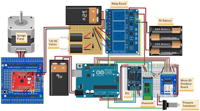
Try to understand what is happening in this figure.
This relaxed Sunday evening I would like to talk on two topics, partly interconnected - what is and how does the engineering approach look like in the development of electronics, and how and why write articles about this electronics on Habr so that they are pleasant and understandable all
The phrase in today's article led me to this idea - “There is a lot of books under the cut, but it will be engineering”; unfortunately, not only there was no engineering under the cut, but also in general a very large percentage of articles on the topic “how I made the device”, published recently on Habré, there is nothing engineering.
')
Why?
Because any engineer - like a programmer, a doctor, a lawyer and any professional in general - has a basic work methodology, without which the activity turns from professional to unsystematic throwing. More precisely, not even the methodology - we can relate the agile, TRIZ to the methodology, and this is all, it is different for everyone - but a rough strategy that can be written in several steps.
So what does this apply to electronics?
1) The formation of the task - or, formally speaking, the formulation of technical specifications.
At the first stage, we formulate what and why we generally want to get, as well as the boundary conditions that we want to meet.
I will not even touch the GPS trackers, the work of the GPS module, the time it takes to enter the coordinate capture mode, etc. - the pieces are quite complex and dependent on many things (I’d just note that any minimally modern GPS module has at least four modes of operation, with a consumption of 20-30 mA, 2-3 mA, 200-300 μA and <10 μA, not counting the full off).
Take a simpler thing - accelerometer. For example, here are three completely real tasks that were solved on a cheap ST LIS3DH MEMS accelerometer:
- tilt angle sensor - tracking the angle of inclination of the lighting column
- physical activity and drop sensor - tracking of free fall facts, as well as assessment of the physical activity of the carrier
- vibration sensor - vibration spectrum tracking 0.1 ... 100 Hz
In all three cases, the devices are on battery power, which we want to optimize for power consumption.
We look at the accelerometer datasheet :
- sleep - 0.5 μA
- 1 Hz - 2 μA
- 25 Hz - 6 μA
- 1344 Hz - 185 μA
Obviously, our three tasks will require three different modes of operation - in the first for the post, even 1 Hz is extremely redundant, the pole usually does not hurry anywhere, and the repair team is not in a hurry all the more. In the second mode is quite adequate mode with a speed of about 25 Hz, and in the third, obviously, it would be nice to have a 10-fold excess of the sampling frequency over the frequency of the measured signal.
Moreover, in the case of a 1 Hz column, it is so redundant that the most effective option is generally to manually poll the accelerometer. For example, our microcontroller wakes up every 15 minutes for such a survey (we agreed with the customer, he is satisfied with such a delay of information about the column about to fall - everything is there until the brigade arrives there in less than two hours), and the controller at the same time, it consumes 5 mA - the average power consumption of the active mode of the controller is 5 * 0.1 / 15/60 = 0.55 μA, which in combination with 0.5 μA of the sleeping accelerometer is approximately twice as profitable as the accelerometer threshing itself by 1 Hz and controller only when the threshold is exceeded.
In fact, what I am describing now is essentially the third stage in the development approach methodology; now it is intended to illustrate how important it is to set a task in advance.
Are you doing a GPS tracker? Fine. You do it for whom? For a pedestrian, with whom he should lie in his pocket, weigh 50 g and live on the battery for a day? For a railroad car, where he has to live for five years, but then weigh at least five kilos? For a cow on free grazing, on which he lives on the battery for the same five years (because the cow no longer lives), but should it weigh a maximum of 35 g, because it is attached to her ear?
These are all completely different tasks.
And it is necessary to say clearly what exactly you are doing and what are the boundary conditions, if hit in which the task can be considered solved, in advance.
Actually, already at this stage, the majority of DIY projects have a black hole: the author does something completely incomprehensible why. Sometimes he honestly writes “to practice soldering,” but most often various abstract ones — without TK they will always be abstract — things like “achieve the minimum power consumption of the processor while simultaneously scoring on the power consumption of everything else” turn out to be an end in themselves.
Take the same article mentioned above - the author of the device chases consumption microamps units , commuting the accelerometer power supply (less than 2 µA in hibernation) and GPS (7-8 µA in battery backup mode) with individual transistors. Is it really necessary? Right in front of me right now is the electronics module for a “smart helmet” (there is also a GPS tracker), it has the required operating time per charge with a margin of 5 mA ( milli amperes) on average in the hospital, do you really think that plus or minus a dozen microamps here have any meaning? And if not, then why on the already quite dense charge to push the extra parts?
2) Selection of components
Once you have decided on the boundary conditions - the second stage begins, in which you choose, from which you will make your device.
The task, in fact, is not very simple, because each component has a bunch of options, such as:
- electrical parameters
- board space
- complexity and cost of installation
- the cost of the component itself
- availability for sale
We take even the same tasks with an accelerometer - well, ok, in a smart helmet you will definitely be satisfied with LIS3DH for half a dollar, the coils lying in Kompale. And on the measurement of the deviation of the post? And with what accuracy does the client want to measure this deviation? Still a cheap 12-bit LIS3DH, a little more expensive 16-bit LIS2HH, or already a top ADXL355 worth fifty dollars bucks and delivering two weeks? Here we return to the boundary conditions of Section 1 and begin to count, count, count.
And it was just an accelerometer. And imagine the variety going on in the market, for example, screens. It is clear that everyone loves WH1602 (although personally I like WEH001602 more), but you will immediately answer what to put in a water meter, which is 6-8 years old, working on one battery, while continuously showing cubic meters?
Actually, each component in the circuit must be justified - the developer either has to understand why the component is exactly like that, or understand that in this case it is all the same (well, for example, resistors are usually more or less what to put, though there are nuances).
And all this is interconnected. For example, the same battery choice is LiMnO 2 with a voltage of 2.0 ... 3.0 V, LiSOCl 2 with a voltage of 2.4 ... 3.6 V or even a rechargeable battery with its 3.0 ... 4 , 2? And what components can work for you from? And from what they will work more efficiently or more economically? And the peak load currents selected element pulls? And if this is LiSOCl 2 , then taking into account passivation, will it still pull? DC / DC boost you want to put, and when not to - turn it off? Does the selected load disconnect chip know how to do it, or does it have a shutdown - is it PWM to stop, and does the output have an input? And there is a danger of overheating, but it may even give you a 1.5-volt LiFeS 2 , for which there is no thermal overclocking, to move?
And so, in a circle several times - changing one component pulls the others along, some…
Do you think the same GPS modules are all the same? Here I have in the same "smart helmet" in the framework of the dimensions agreed with the customer and within the framework of the commercially available battery that meets the battery requirements, you will have to put something on the side of the board adjacent to the case and having in view this restriction on the height of these components 1.5 mm. Now pick up the nearest GPS module and measure how much body height it has.
Yeah. Exactly. Well, you can renegotiate the dimensions and make the body 1 mm thicker, but you can also change the usual Quectel L76 to a new EVA M8M with its 7 × 7 × 1.1 mm.
What do we see in the above article? The author does not know why he makes the GPS tracker, so he puts the first GPS module in it, about which he does not know about the operating modes and doesn’t want to learn, therefore, for the sake of energy saving (it’s also not very clear why) cuts him all the food.
That is - failure in the formation of the task leads to failure in the choice of components.
3) Production of a prototype product
Well, here, probably, there is nothing much to dwell on - after selecting the components, the final scheme, the board, the prototypes are assembled. With DIY, everything is usually more or less good, and the fact that blue electrical tape and multi-colored wires are gradually replaced by custom boards is welcome.
4) Optimization of component operation modes
Despite all your efforts, the previous stages will leave separate white spots - in many cases you will always have room for fine tuning of the components (GPS, by the way, is a good example - you can play with them for a long time with setting inactivity modes to minimize power consumption while ensuring given reliability of coordinates). Many nuances to find out by datasheets are either difficult or impossible at all - manufacturers often do not indicate too detailed data or relationships between different parameters.
Therefore, after the manufacture of the prototype, which, according to your preliminary estimates, should fall into the requirements of the TOR, the stage of its optimization begins.
There is, for example, a classic example - the power consumption of a processor as a function of its speed. Yes, the more megahertz - the more milliamps. But the faster the processor performs the task and goes back to sleep! But at the same time, the task may partially depend on the speed of external interfaces, which work equally well at 1 MHz, which at 64 MHz. At the same time, the output of the processor at 64 MHz may take longer than outputting it at 4 MHz (starting and stabilizing the quartz resonator, starting and stabilizing the PLL, reconfiguring the clocking modes), and as a result, from on to off, the same task in the first case eat more microamperes seconds than the second!
Here, of course, often you should not get too carried away - if you get into the boundary conditions of a TK with a good margin, then there is little point in wasting time on optimization; Well, as in the aforementioned “smart helmet”, with which, with an average consumption of 5 mA, there is simply no point in saving units and even dozens of microamperes, this is an error, not a saving.
At the same stage, various assumptions can be checked - for example, the author of the article on the GPS-tracker suggested that devices with high consumption would be more economical if they were powered with less voltage. In practice, this is not always the case - if the module has a pulse converter as part, then in any case it consumes constant power, which means that if the voltage drops, it will increase the current consumption.
As a result, the total consumption of the circuit, in which one more downconverter was added, and then also the level matching chains, will only grow.
5) Experimental proof of the optimal solution of the problem
The last stage (which, however, can be partially performed at the last but one) is an experimental proof that the device is made correctly and optimally.
First, it is worth taking a look once again - if unnecessary details were found in the process of prototyping and debugging. Overaining, in which the device gets a lot of superfluous, is generally very characteristic of DIY projects - take, for example, a recent article about a touch switch , the author of which, having a powerful microcontroller at hand, made touch sensors on individual chips, and then also failed to keep power consumption resulting in any acceptable framework. Well, or the common belief among arduinschikov that for "protection from interference" the output of the microcontroller and the gate of the transistor controlling the relay should be separated by an optocoupler.
However, in these cases, the critical examination of their projects would not help the authors in any way - they obviously have an acute shortage of basic knowledge that allows them to solve the problem in an optimal way, rather than making additional components with the functionality that they don’t understand. Nevertheless, go through the scheme and think about whether something was not really necessary on it - signals, tracks, components - is worth it.
Secondly, it is necessary to understand whether the device really satisfies the boundary conditions of the TK, and if not - or even if its parameters simply do not fit into your ideas about what they should be - then why (yes, I specifically singled out bold: worthless to the developer who, having received a power consumption of 40 μA instead of the estimated 5-10 μA, cannot explain why).
There are no cases of “well, everyone understands that 10 μA is written in the datasheet, but in reality, less than 100 μA will not work” in nature does not happen . Either there is a very specific error in datasheet, a zero, for example, was not printed, or you do not understand something. Let's be honest, the probability that you will encounter such an error is rather small in professional activity and is practically zero in DIY projects, this is one case for many thousands of components and, as a rule, in some exotic modes of their work - therefore, if The parameters of your device strongly and objectively do not coincide with what you counted on a napkin on a datasheet, this means that you do not understand something.
I saw a lot of examples of this in the same energy consumption issue - digital inputs left in the air, non-switched CPU peripherals, forgotten power-ups ... But I don’t remember a single case where it would turn out that “in reality “, And the consumption would not have been possible either to bring to the settlement, or to correct the calculations taking into account the factors explicitly indicated in the datasheets, but by mistake not previously taken into account.
The study of such questions is usually quite nontrivial, but it is necessary. If your calculations do not agree with your measurements, it means either you made a mistake in others, and errors should be corrected.
So what about the article to write?
So in conclusion - about what to write on Habr so that you do not have any complaints from professionals, which we consider here as a significant part of the audience.
In fact, those articles on electronics design that I regularly see fall into one of the groups:
- information garbage duplicating the first page of Google issue
- biography "how I spent the weekend"
- guide on how to make yourself some device
- analysis of non-obvious majority of subtleties
A good example of the latter - for example, the latest article Hardware bit banding CortexM3 / M4 . The content of such articles is not necessarily a scientific discovery, but in any case is a detailed enough analysis for practical application that is unknown to most people. Such articles are of different complexity and different specificity, but they are all united by the fact that you would, of course, find information from them yourself, but sooner or later you would spend time much more than reading the article.
The diametrical opposite of them is the articles “how to blink a LED with the help of a multivibrator”. It’s not that they contain incorrect or unnecessary information, but if all the same information can be obtained from almost any link on the first page of Google issue on the corresponding request, then the value of such an article is generally zero. This is rubbish, an article for the sake of an article.
There are, however, articles that are useful, but do not contain fundamentally new information - these are guidelines on how to make yourself some kind of device based on the personal experience of the author. As a rule, these are relatively simple things (complex, going through the entire design path described above, appear in the form of articles "as we did" and in fact quickly fall into the enumeration of subtleties that appear in the process that are not obvious to most subtleties, falling into the appropriate category) given in the articles, it is necessary and sufficient for self-repetition and further development by the readers of the device. These are diagrams, firmware, explanations why the device is made exactly the way it can be made.
Finally, the article-biography - and the touch button and the GPS tracker fall into this category, the most mysterious genre for me. Their authors write a lot - sometimes a lot - of letters, abundantly accompanied by pictures, but an outsider cannot extract anything useful from them . The authors in no way justify the solutions they choose, often do not indicate at all what they are doing all this for, often do not give basic diagrams or source codes of the firmware, not only in whole, but at least in significant parts, they do not indicate any specific problems, arisen in the process and which can be interesting for people around (“at first I didn’t know how to solder SMD components, but over time I learned” is not a problem that is interesting for those around me).
Although such an article looks superficially like a deep technical work, in fact it is a school essay “How I spent the summer”, of little interest to anyone except the author himself.
If possible, avoid this.
PS Since there must be some illustrations in the article, I will give an example, for which people do not like people who claim that the picture from Fritzing is the full-fledged electrical circuit:
Try to understand what is happening in this figure.
Source: https://habr.com/ru/post/454532/
All Articles