Developing a simple music synthesizer on ATMEGA8
A few years ago, I made an alarm clock on the ATmega8 microcontroller, where I implemented a single-tone (monophonic) simple melody synthesizer. There are many articles for beginners on the Internet devoted to this topic. As a rule, a 16-bit timer is used to generate the frequency (notes), which is configured in a certain way, forcing at the hardware level to issue a signal in the form of a meander on a certain MK pin. The second (8-bit) timer is used to realize the duration of a note or pause. Notes by known formulas are matched with frequencies, and they, in turn, are matched with certain 16-bit numbers, inversely proportional to the frequencies that define the timer counting periods.
In my design I provided for three melodies that were written in the same key and scale. Thus, I had to use a limited and certain number of notes, which made modeling easier. In addition, all three tunes were played at the same tempo. The code of the note and the code of its duration easily fit into one byte. The only drawback of this model was the lack of universality, the ability to quickly edit, replace or complement the melody. In order to record a melody, I first sketched it in a musical editor on a computer, then rewrote the notes and their durations, with which I was pre-determined, and then formed the resulting bytes. Recent operations done using Excel.
In the future, I wanted to eliminate the above disadvantage, betraying the design of a certain universality and reducing the time to implement the melody. There was such an idea that the MK program read the bytes of one of the well-known music formats. The most popular and common format is MIDI. Literally speaking, this is not so much a format as a whole “science” about which you can read on the Internet. The MIDI specification defines a real-time messaging protocol using a corresponding physical interface and describes how midi files are organized in which these messages can be stored. The midi format is music-oriented, and therefore finds use in the relevant field. This is a synchronous control of sound equipment, color music, music synthesizers and robots, etc. In the domestic sphere, the midi format met in the era of the beginning of the development of mobile phones. In this case, messages about turning on or off a particular note, information about a musical instrument, the volume of the notes and so on are recorded in the midi file. A mobile phone that plays such a file contains a synthesizer that interprets midi messages in this file in real time and plays the melody. At the earliest stages, the phones were able to reproduce only single-tone melodies. Over time, the so-called polyphony.
On the Internet, I met articles about the implementation of a polyphonic synthesizer on the MK, which reads midi files. In this case, at a minimum, a preformed “wave table” (a list of sound wave forms) is used for each musical instrument stored in the memory of the MC. And in my particular case, the discussion will deal with the implementation of a simpler model: a single-tone (monophonic) synthesizer.
')
To begin with, I carefully studied the midi file device, concluding that, in addition to the necessary information about the notes, it contains additional redundant information. Therefore, it was decided to write a simple program to convert the midi file to your format. The program, working with many midi files, not only converts formats, but also organizes them in a certain way. In advance, I decided on the organization of storing a variety of melodies in the ROM memory (EEPROM 24XX512). For the convenience of visualization in the HEX editor, I made sure that each tune starts from the beginning of the sector. Unlike an SD card (for example), the concept of a sector is inapplicable to the ROM used, so I express myself conditionally. The sector size is 512 bytes. And the first sector of the ROM is assigned to the addresses of the sectors that started each tune. It is assumed that the melody can take several sectors.
A full description of the midi file format, of course, is not worth producing here. I will touch only the most necessary and necessary moments. Midi file contains 16 channels, which, as a rule, most often, corresponds to a particular musical instrument. In our case, it does not matter what the instrument is, and only one channel is needed. The content of each channel, together with the title, is made into a midi file according to a principle that is very similar to organizing the storage of video and audio streams in an AVI container. I wrote about the latter earlier in one of my articles. The header of the midi file is a set of some parameters. One of these parameters is the resolution in time. It is expressed in the number of “ticks” (a kind of pixel) per quarter (PPQN). A quarter is a time period during which a quarter note is sounded. Depending on the tempo of the melody, the length of the quarter may be different. Consequently, the duration of one “pixel” (sampling period) depends on the tempo and PPQN. All information about the time of an event is determined to the accuracy of this duration.
In addition, the header contains the type of midi file (type 0 or type 1) and the number of channels. Without going into details, we will work with type 1, the number of channels 2. A midi file with a single-tone melody, logically, contains one channel. But in the midi file “type 1” there is, besides the main one, another “non-musical” channel, in which additional information is recorded that does not contain notes. This is the so-called metadata. Here also it is not necessary to go into details. The only information we need that lies there is information about the pace, and in an unusual format: microseconds by a quarter. In the future, it will be shown how to use this information, together with PPQN, to configure the timer MK, which is responsible for the temp.
In the block of the main channel with notes, we are only interested in information about events of turning on and off notes. The note triggering event has two parameters: the number and the volume of the note. A total of 128 notes and 128 volume levels are provided. We are only interested in the first parameter, because it doesn’t matter what volume the note has: all notes will play with the same volume when played on the MC melody. And, of course, in the melody there should not be notes “with imposition”, that is, at any moment of time there should not be more than one note at a time. The code of the event of taking (turning on) the note is 0x90. The event code for turning off the note is 0x80. However, at least the “Cakewalk Pro Audio 9” editor does not use event code 0x80 when exporting songs to midi format. Instead, the event 0x90 is valid throughout the musical part, and a zero volume is a sign of a note turning off. That is, the event “turn off the note” is equivalent to the event “turn on the note with zero volume”. Perhaps this is done for reasons of economy. According to the specification, the event code can not be re-written if this event repeats. Between events, information about the time interval is recorded in a variable length format. These are the integer values of the number of “ticks” mentioned above. Most often, one-byte is enough to record a time interval. If two events follow one after another, then the time interval between them, obviously, is equal to zero. This, for example, is turning off the first one and turning on the second note following it, if there is no pause (space) between them.
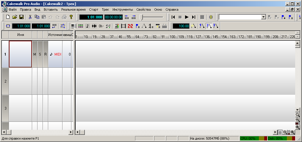
Let's try using the program "Cakewalk Pro Audio 9" to write a sequence of notes. There are many editors, but I settled on the first one.
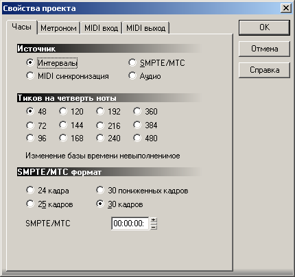
First you need to adjust the project settings. In this editor, you can set the resolution in time (PPQN). I choose the minimum value of 48. Too much value to choose is meaningless, because I have to work with large numbers that are larger than 1 byte. But the minimum value of 48 is quite satisfied. In almost every melody there are no notes shorter than 1/32. And if the number of “ticks” per quarter is 48, then the note or pause 1/32 will have a duration of 48 / (32/4) = 6 “ticks”. That is, there is a theoretical possibility to completely divide the 1/32 note by 2, and even by 3. The remaining parameters in the project properties window are left as default.
Next, open the property of the first track and assign it a channel number equal to 1. To your taste, select the patch that corresponds to the musical instrument when playing a melody in the editor. Of course, the number of the patch will not affect the final result.

The tempo of the melody is set in the number of quarters per minute on the editor toolbar. The default tempo value is 100 bpm.
The microcontroller has an 8-bit timer, which, as already mentioned, will be used to control the duration of the sounding notes and pauses. It was decided that the time interval between adjacent triggers (interrupts) of such a timer would correspond to the interval of one “tick”. Depending on the melody tempo, the value of this time interval will be different. I decided to use interrupt timer overflow. And depending on the initialization parameter of the timer, it is possible to adjust this same time interval, which depends on the tempo of the melody. We now turn to the calculations.
As a rule, in practice, on average, the tempo of the songs lies in the range of the order of 50 to 200. It has already been said that the tempo in the midi file is set by microseconds per quarter. For tempo 50, this value is 60000000/50 = 1200000, and for tempo 250 it will be 240,000. Since, according to the project, there are 48 ticks in the quarter, the length of the tick for the minimum rate will be 1200000/48 = 25000 μs. And for the maximum rate, if you calculate the same way, - 5000 μs. For MK with a frequency of 8 MHz quartz and a maximum pre-divider of the timer equal to 1024, we get the following. For the minimum tempo, the timer must be calculated 25000 / (1024/8) = 195 times. The result is rounded to the nearest integer value, the rounding error almost does not affect the result. For the maximum rate - 5000 / (1024/8) = 39. Here, the rounding error does not affect all the more, since the rounded value 39 is obtained for the adjacent tempo values from 248 to 253. Accordingly, the timer must be initialized with an inverse value: for the minimum tempo - (256-195) = 61, and for the maximum - (256 -39) = 217. The minimum rate at which work with the timer in the current MK configuration will be provided is 39 bpm. With this value, the timer must be counted 250 times. And with a value of 38 - already 257, which goes beyond the limit of the timer. I decided to take the value of 40 bpm for the minimum rate, and 240 for the maximum.
A virtual timer based on the above will be used to calculate the number of ticks. It is the number of ticks and sets the duration of the note or pause, as already mentioned above.
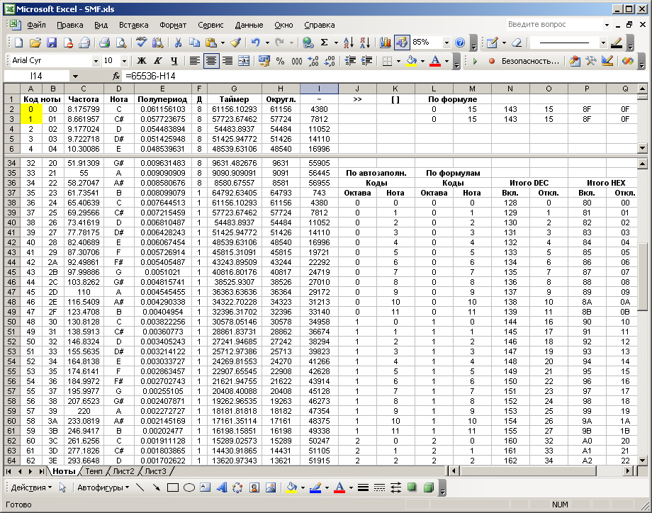
A second, 16-bit timer is used to implement note playing. According to the midi specification, a total of 128 notes are provided. But in practice, they are used much less. Moreover, the notes of the lowest (with frequencies around 50 Hz) and the highest (with frequencies around 8 kHz) octaves will be reproduced by the microcontroller not quite harmoniously. But with all this, the 16-bit timer with a fixed divider covers almost the entire range of notes provided by the midi, namely, without the first 35. But I chose a note with the number 37 as the beginning (its code is 36, since the encoding comes from zero). This is done for convenience, since this number corresponds to the note “C”, as the first note in the traditional scale. It corresponds to the frequency of 65.4 Hz, and the half-period is - 1 / 65.4 / 2 = 0.00764 sec. This time period at a frequency of 8 MHz MK and a divider 1 (that is, without a divider), the timer counts approximately as a whole for 0.00764 / (1/8000000) = 61156 times. For the 35th note, if we calculate, this value will be 68645, which is beyond the counting range of the 16-bit timer. But, even if there was a need to reproduce notes, below the 36th, you can enter the first available timer divider equal to 8. But there is no practical need for this, as there is not even to play the highest notes. However, for the topmost 128th note, the “G” note with a frequency of 12,543.85 Hz, the timer value is, if you count, similarly, 319. The specificity of all the above calculations is due to a certain configuration of the timer mode, which will be shown later.
Now I have an equally important question: how to get the relationship between the note number and the code for the timer? There is a well-known formula for calculating the frequency of a note by its number. And the timer code for a known frequency is calculated easily, as was shown above in the examples. But in the formula of frequency versus note, the root of the 12th degree appears, and in general, I would not want to load the controller with such computational procedures. On the other hand, creating an array of timer codes for all notes is also not rational. And I decided to do the following, choosing a middle ground. It is enough to create an array of timer codes for the very first 12 notes that make up one octave. And the notes of the following octaves are obtained by successively multiplying the frequencies of the notes of the first octave by 2. Or, the same thing, by sequentially dividing the values of the timer codes by 2. Another convenience is that the octave number serves, by coincidence, as an argument in the bitwise right shift operation ( "), Which will be used as a division by powers of two. I chose this operator not by chance, since its argument reflects the exponent of the two of the divisor (the number of divisions by 2). And this is the number of the octave. For the set of notes used by me, a total of 8 octaves are involved (the last octave is incomplete). The note in the midi file is encoded with one byte, more precisely, with 7 bits. In order to reproduce the notes in the MC, according to the foregoing idea, it is necessary first of all to calculate by the code of the note the number of the octave and the number of the note in the octave. This operation is performed at the stage of converting the midi file into a simplified format. Eight octaves, just, can be encoded with three bits, and 12 notes in an octave - four. In total, it turns out that the note is encoded with the same seven bits, as in the midi file, but only in a different representation, convenient for the MC. Due to the fact that 4 bits can encode 16 combinations, and notes in octave 12, there are unused bytes.
The last eighth bit can be used as a note on or off marker. In the case of MC, in view of the monophonicity of the melody, the information about the note being turned off will be redundant. With a direct change of note in the melody, it is not a “switch-off”, but a “switch” of the note. And in the case of a pause, “silence is turned on,” for which you can select a special byte from the set of unused bytes, and the information about turning off a note should not be used at all. This idea is good because it saves the size of the resulting melody after the conversion, but generally complicates the model. I did not follow this idea, as there is plenty of memory already.
Information about the notes of the melody in the midi file is stored in the block of the corresponding channel in the "interval-event-interval-event ..." view. In the converted format, the exact same principle applies. To record the event (turn on or turn off the note) is used, as mentioned above, one byte. The first bit (the most significant bit 7) encodes the type of event. The value “1” is the turning on of the note, and the value “0” is the turning off. The next three bits encode the octave number, and the lowest four bits encode the octave note number. One byte is also used to record the time interval. In the original midi format, a variable-length format is used for this. Its small drawback is that only 7 bits encode a time interval (the number of “ticks”), and the eighth bit indicates a continuation. That is, in one byte, in fact, you can encode an interval of up to 128 ticks. But since the time intervals between events in real and simple melodies sometimes exceed 128, but almost never exceed 256, I abandoned the variable-length format and cost one byte. It is he who codes the time interval to 256 ticks. Since the project uses 48 ticks per quarter, or, 48 * 4 = 192 ticks per clock, then one byte can encode an interval of 256/192 = 1. (3) (one integer and one third) clock time, which quite enough.
In a proprietary format that converts the midi file, I also applied a small header, 16 bytes in size. The first 14 bytes contain the name of the melody. Naturally, the length of the name should not exceed 14 characters. Then follows a zero space. The next last byte reflects the tempo of the melody in a presentation convenient for the MC. This value is calculated at the transformation stage and is used to initialize the MK timer, which is responsible for the temp. About how it is calculated, mentioned several paragraphs above.
Starting from the 17th byte, the content of the tune follows. Each odd byte corresponds to the time interval, and each even byte - to the event (note). , , , . 0xFF. . , . , , , , . . 0x0F, . 16- , , 12. . , « », , . ( ). , 36 . , ( ) , .
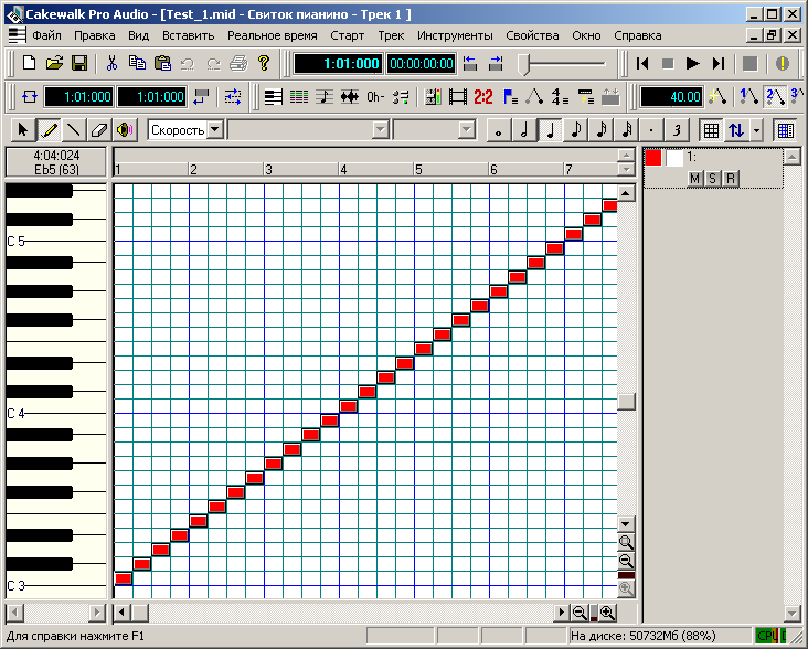
«Cakewalk Pro Audio 9», . , . : «Piano roll» . . .
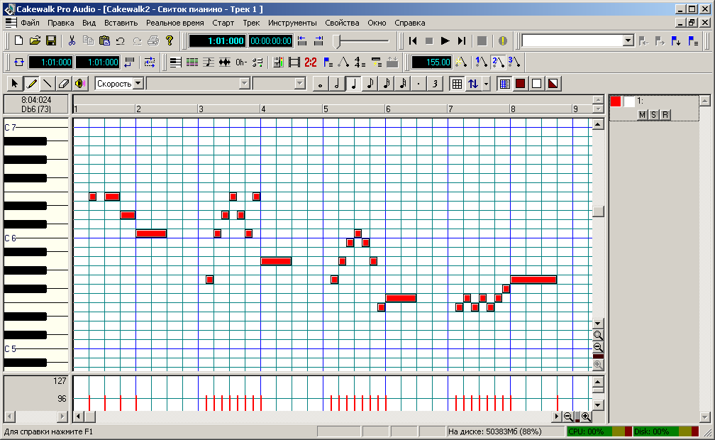

, () , . , , .
.
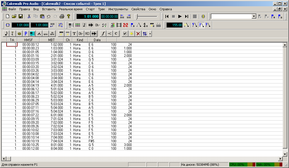
, , , . , , - , «Del». , , - «». , , . , , . , : .
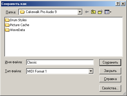
« 1», .
HEX . , , avi ( ), , (big endian).
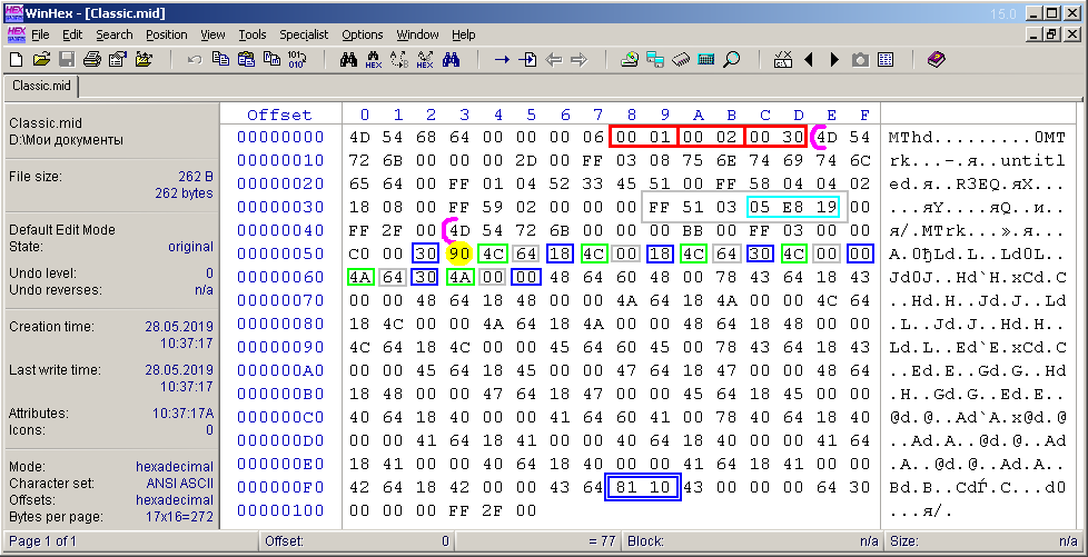
. . , (1), (2) (48). . . 6 , . 6 (- 0xFF) 0x51 0x03 . – . . , . . – – . , , , , . ( ) , 48*3=144 128. , . 144 . . , . . , () , : . , 0x90, . . – , 128 .
Again, as mentioned above, the program for converting a midi file into its own format for the MK actually works with a group of several midi files, and on the output creates an image file for EEPROM. Consider a fragment from this file that relates to the contents of the converted melody from the example above. I opened it in another HEX editor to show the image by sector and pay attention to it. Each new tune starts with a new sector.
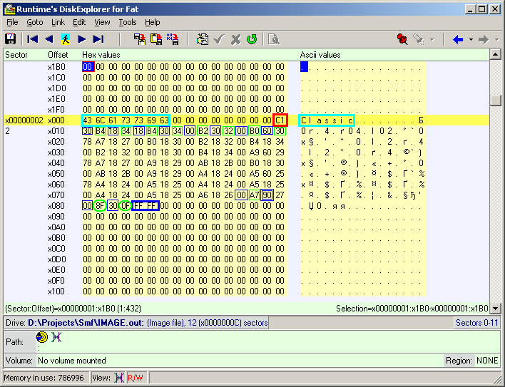
( 16 ), , . 0xC1 (193) 154, 155 156. , 155 bpm, . ( 14-), , . – «Classic». , HEX . , , , .
( 17- ) . , , . , , . , , /. , «» , 0xB4 0x34, 0x34, . 0xB4 (0b10110100) , , 0x34 (0b00110100) , . 0x34 : 0b011, – 0b0100. , , 3 4 . , , . . , Excel, 76 (0x4C) , E6 ( «» 6- ). : .
, . , , . , . , . . , . , , - , , , . , , , 1 . «» 1 , .
(0x90), 128, , . . , , . , 0xFF, , . , .
Consider the very first sector of the output EEPROM image file. As I already wrote, it serves as a list of the addresses of the sectors that started the melodies. The program successfully scanned 8 melodies without errors (at the time of writing, I recorded 8 melodies). The value of the number of melodies is recorded in the last 512th byte of the sector. And from the very beginning of the sector addresses are recorded. For the first melody, the address is 0x01, which corresponds to the second sector (the first, if we count from zero). The third and fourth melody (two of eight) turned out to be long and did not fit in one sector. Therefore, there are gaps in the address sequence. In memory, 64kB in size, if you count, you can record no more than 127 melodies, so one sector for addressing is enough.

, , Excel. ( ).
, , . , . , , , .
The basic part of the program for MK, in fact, is very simple. Consider one of the options for its implementation, more precisely, its main part.
Timer 1, used to generate note sound, is configured as follows. To enable and disable notes, use the following substitutions respectively.
Before turning on the timer, you need to assign a 16-bit value to the OCR1A register, which will correspond to the reproduced frequency. This will be shown below. When the timer is enabled, the TCCR1B register is assigned the “Waveform Generation Mode” with a timer divider of 1, and the TCCR1A register is assigned to “Toggle OC1A on Compare Match”. In this case, the signal is removed from a specially assigned output of the MK "OC1A". In the ATmega8 in the SMD package, this is pin 13, which is the same as PORTB.1. When the timer is turned off, both registers are reset, and the PORTB.1 output forcibly becomes zero. This is necessary in order to prevent a constant voltage output during silence, which will be undesirable for ULF input. Although it is possible to put a capacitor in the circuit, it is also possible to disable the output programmatically. A constant voltage may occur on this pin if the note is turned off at the moment of the corresponding phase of the signal, which is 50% of the time.
Create an array of timer values for 12 notes of the very first octave. These values were calculated in advance.
The values of the notes of the other octaves, as I said, will be obtained by dividing by powers of two.
Timer 0 configuration is even simpler. He works constantly, with interruption on overflow, each time being initialized anew by the value that corresponds to the tempo of the melody. The timer divider is 5: TCCR0 = 0x05. Based on this timer, a virtual timer has been created that counts ticks (lengths of time) into a melody. The response processing for this timer is placed in the main program loop.
The timer interrupt function 0 looks like this.
Here the variable ent01 is responsible for activating the virtual timer. For this variable, you can enable or disable it, if necessary. The variable vt01 is the countable main variable of the virtual timer. The string TCNT0 = top0 indicates the initialization of timer 0 to the desired value of top0, which is read from the melody header before it is played.
The number of the melody to be played corresponds to the variable alm. It also serves as a flag for the start of playback. She needs to assign a melody number in one of the ways, depending on the task. After that, the next block of the main loop will become active.
Further switching from note to note is carried out in the processing unit of the virtual timer, which is also placed in the main loop.
From the comments in the text of the program everything should be quite clear and understandable.
To stop the melody, the following insert of the main loop is applied.
There is a small note about the implementation of the playback of the melody. Before the start of each new note, the microcontroller spends a small amount of time converting the read byte of the note into the value of the timer value. This time, as it turned out in practice, is relatively short, and does not affect the quality of reproduction. But I had doubts that this operation would remain unnoticeable. In this case, there would be extra pauses before each note, and the rhythm of the melody would be broken. But this problem is also solved. It is enough to calculate the values of the timer of the next note in advance, while the current note sounds. This procedure for a specially designated flag must be performed separately from the processing of the virtual timer in the main program loop. Due to the fact that the calculation time is unlikely to exceed the time of sounding even the shortest note, this decision is appropriate.
We now turn to testing the program.
In addition to the above code snippets, I added the button handling functions to the MK program, with which I can control the on or off of a particular melody. The EEPROM is connected to the MC via I2C bus, the work with which is implemented at the program level. The project was done with the help of CodeVisionAVR together with CodeWizardAVR. The output of the MK from pin 13 is sent to the PC sound card through a divider and I record the sound of the melody in the sound editor. I flashed the EEPROM memory using software and hardware, which I wrote about in a previous article. Due to the fact that not all bytes of the image file are useful, the memory can be flashed only by useful bytes (until the end of the ring tones) in order to save recording time and chip life. To do this, you can make a separate program, or write bytes to the chip directly during the conversion, adding to the main program.
Among the eight melodies, there are three test ones, with the help of which I will estimate by ear the frequency range, the sound of merging identical notes, the sound of the shortest notes, the fast transitions, etc. Let me remind you that merging identical notes actually sound with a pause of one tick, and the first note in a merge lasts one tick less.
One of the test melodies is a sequence of notes from first to last with a one-quarter note lasting one quarter and a melody tempo of 40 bpm.
In this scenario, one note sounds a little more than a second, and therefore you can listen in detail how the whole range of notes sounds. On the frequency spectrum in the audio editor "Adobe Audition", the main frequency components and their upper harmonics are observed due to the corresponding sawtooth waveform. And also the logarithmic relationship between the note number and frequency is striking.

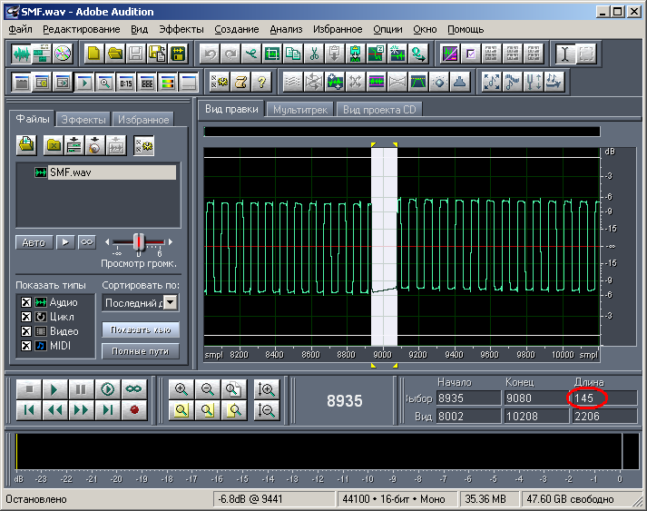
Analyzing the time intervals, it is clearly seen that the real pause between consecutive notes averages approximately 145 samples (at a sampling frequency of audio recordings of 44,100 Hz), which is about 3 ms. This is the time during which the MC makes the necessary calculations. These inserts are present regularly before each note. I specifically wrote the value in the samples, since this information is more original and more accurate, although this is not very important.
And the length of one tic with an average melody tempo of 120 bpm is about 10 ms. It follows that, in principle, it would be possible not to introduce the very amendment to 1 tick, when two identical notes go one after the other without a pause. I think that a regular insert in 3 ms between notes would be quite enough. When listening to the melody, these regular inserts are generally not noticeable, and the melodies sound exactly. Therefore, there is no special need to calculate the timer value for the next note while the current one sounds.
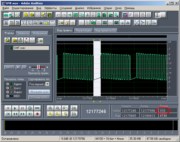
Another test melody with a tempo of 200 bpm contains identical 1/32 notes in a row from the middle range without a pause. In this case, after processing, during playback, there is a 1 tick pause between them, which is 310 samples (about 6 ms) of the recorded signal at this fast pace.
The length of this pause, by the way, is comparable to the period of the signal, which indicates a high tempo of the melody. And its sound is like a trill.
In principle, this can be finished. I was satisfied with the result of the device, it exceeded all expectations. Most of the time I spent studying the midi format and debugging the program for conversion. I will also devote one of the following articles to a topic related to midi, where I will be told about the use of this format in other interesting applications.
In my design I provided for three melodies that were written in the same key and scale. Thus, I had to use a limited and certain number of notes, which made modeling easier. In addition, all three tunes were played at the same tempo. The code of the note and the code of its duration easily fit into one byte. The only drawback of this model was the lack of universality, the ability to quickly edit, replace or complement the melody. In order to record a melody, I first sketched it in a musical editor on a computer, then rewrote the notes and their durations, with which I was pre-determined, and then formed the resulting bytes. Recent operations done using Excel.
In the future, I wanted to eliminate the above disadvantage, betraying the design of a certain universality and reducing the time to implement the melody. There was such an idea that the MK program read the bytes of one of the well-known music formats. The most popular and common format is MIDI. Literally speaking, this is not so much a format as a whole “science” about which you can read on the Internet. The MIDI specification defines a real-time messaging protocol using a corresponding physical interface and describes how midi files are organized in which these messages can be stored. The midi format is music-oriented, and therefore finds use in the relevant field. This is a synchronous control of sound equipment, color music, music synthesizers and robots, etc. In the domestic sphere, the midi format met in the era of the beginning of the development of mobile phones. In this case, messages about turning on or off a particular note, information about a musical instrument, the volume of the notes and so on are recorded in the midi file. A mobile phone that plays such a file contains a synthesizer that interprets midi messages in this file in real time and plays the melody. At the earliest stages, the phones were able to reproduce only single-tone melodies. Over time, the so-called polyphony.
On the Internet, I met articles about the implementation of a polyphonic synthesizer on the MK, which reads midi files. In this case, at a minimum, a preformed “wave table” (a list of sound wave forms) is used for each musical instrument stored in the memory of the MC. And in my particular case, the discussion will deal with the implementation of a simpler model: a single-tone (monophonic) synthesizer.
')
To begin with, I carefully studied the midi file device, concluding that, in addition to the necessary information about the notes, it contains additional redundant information. Therefore, it was decided to write a simple program to convert the midi file to your format. The program, working with many midi files, not only converts formats, but also organizes them in a certain way. In advance, I decided on the organization of storing a variety of melodies in the ROM memory (EEPROM 24XX512). For the convenience of visualization in the HEX editor, I made sure that each tune starts from the beginning of the sector. Unlike an SD card (for example), the concept of a sector is inapplicable to the ROM used, so I express myself conditionally. The sector size is 512 bytes. And the first sector of the ROM is assigned to the addresses of the sectors that started each tune. It is assumed that the melody can take several sectors.
A full description of the midi file format, of course, is not worth producing here. I will touch only the most necessary and necessary moments. Midi file contains 16 channels, which, as a rule, most often, corresponds to a particular musical instrument. In our case, it does not matter what the instrument is, and only one channel is needed. The content of each channel, together with the title, is made into a midi file according to a principle that is very similar to organizing the storage of video and audio streams in an AVI container. I wrote about the latter earlier in one of my articles. The header of the midi file is a set of some parameters. One of these parameters is the resolution in time. It is expressed in the number of “ticks” (a kind of pixel) per quarter (PPQN). A quarter is a time period during which a quarter note is sounded. Depending on the tempo of the melody, the length of the quarter may be different. Consequently, the duration of one “pixel” (sampling period) depends on the tempo and PPQN. All information about the time of an event is determined to the accuracy of this duration.
In addition, the header contains the type of midi file (type 0 or type 1) and the number of channels. Without going into details, we will work with type 1, the number of channels 2. A midi file with a single-tone melody, logically, contains one channel. But in the midi file “type 1” there is, besides the main one, another “non-musical” channel, in which additional information is recorded that does not contain notes. This is the so-called metadata. Here also it is not necessary to go into details. The only information we need that lies there is information about the pace, and in an unusual format: microseconds by a quarter. In the future, it will be shown how to use this information, together with PPQN, to configure the timer MK, which is responsible for the temp.
In the block of the main channel with notes, we are only interested in information about events of turning on and off notes. The note triggering event has two parameters: the number and the volume of the note. A total of 128 notes and 128 volume levels are provided. We are only interested in the first parameter, because it doesn’t matter what volume the note has: all notes will play with the same volume when played on the MC melody. And, of course, in the melody there should not be notes “with imposition”, that is, at any moment of time there should not be more than one note at a time. The code of the event of taking (turning on) the note is 0x90. The event code for turning off the note is 0x80. However, at least the “Cakewalk Pro Audio 9” editor does not use event code 0x80 when exporting songs to midi format. Instead, the event 0x90 is valid throughout the musical part, and a zero volume is a sign of a note turning off. That is, the event “turn off the note” is equivalent to the event “turn on the note with zero volume”. Perhaps this is done for reasons of economy. According to the specification, the event code can not be re-written if this event repeats. Between events, information about the time interval is recorded in a variable length format. These are the integer values of the number of “ticks” mentioned above. Most often, one-byte is enough to record a time interval. If two events follow one after another, then the time interval between them, obviously, is equal to zero. This, for example, is turning off the first one and turning on the second note following it, if there is no pause (space) between them.
Let's try using the program "Cakewalk Pro Audio 9" to write a sequence of notes. There are many editors, but I settled on the first one.
First you need to adjust the project settings. In this editor, you can set the resolution in time (PPQN). I choose the minimum value of 48. Too much value to choose is meaningless, because I have to work with large numbers that are larger than 1 byte. But the minimum value of 48 is quite satisfied. In almost every melody there are no notes shorter than 1/32. And if the number of “ticks” per quarter is 48, then the note or pause 1/32 will have a duration of 48 / (32/4) = 6 “ticks”. That is, there is a theoretical possibility to completely divide the 1/32 note by 2, and even by 3. The remaining parameters in the project properties window are left as default.
Next, open the property of the first track and assign it a channel number equal to 1. To your taste, select the patch that corresponds to the musical instrument when playing a melody in the editor. Of course, the number of the patch will not affect the final result.
The tempo of the melody is set in the number of quarters per minute on the editor toolbar. The default tempo value is 100 bpm.
The microcontroller has an 8-bit timer, which, as already mentioned, will be used to control the duration of the sounding notes and pauses. It was decided that the time interval between adjacent triggers (interrupts) of such a timer would correspond to the interval of one “tick”. Depending on the melody tempo, the value of this time interval will be different. I decided to use interrupt timer overflow. And depending on the initialization parameter of the timer, it is possible to adjust this same time interval, which depends on the tempo of the melody. We now turn to the calculations.
As a rule, in practice, on average, the tempo of the songs lies in the range of the order of 50 to 200. It has already been said that the tempo in the midi file is set by microseconds per quarter. For tempo 50, this value is 60000000/50 = 1200000, and for tempo 250 it will be 240,000. Since, according to the project, there are 48 ticks in the quarter, the length of the tick for the minimum rate will be 1200000/48 = 25000 μs. And for the maximum rate, if you calculate the same way, - 5000 μs. For MK with a frequency of 8 MHz quartz and a maximum pre-divider of the timer equal to 1024, we get the following. For the minimum tempo, the timer must be calculated 25000 / (1024/8) = 195 times. The result is rounded to the nearest integer value, the rounding error almost does not affect the result. For the maximum rate - 5000 / (1024/8) = 39. Here, the rounding error does not affect all the more, since the rounded value 39 is obtained for the adjacent tempo values from 248 to 253. Accordingly, the timer must be initialized with an inverse value: for the minimum tempo - (256-195) = 61, and for the maximum - (256 -39) = 217. The minimum rate at which work with the timer in the current MK configuration will be provided is 39 bpm. With this value, the timer must be counted 250 times. And with a value of 38 - already 257, which goes beyond the limit of the timer. I decided to take the value of 40 bpm for the minimum rate, and 240 for the maximum.
A virtual timer based on the above will be used to calculate the number of ticks. It is the number of ticks and sets the duration of the note or pause, as already mentioned above.
A second, 16-bit timer is used to implement note playing. According to the midi specification, a total of 128 notes are provided. But in practice, they are used much less. Moreover, the notes of the lowest (with frequencies around 50 Hz) and the highest (with frequencies around 8 kHz) octaves will be reproduced by the microcontroller not quite harmoniously. But with all this, the 16-bit timer with a fixed divider covers almost the entire range of notes provided by the midi, namely, without the first 35. But I chose a note with the number 37 as the beginning (its code is 36, since the encoding comes from zero). This is done for convenience, since this number corresponds to the note “C”, as the first note in the traditional scale. It corresponds to the frequency of 65.4 Hz, and the half-period is - 1 / 65.4 / 2 = 0.00764 sec. This time period at a frequency of 8 MHz MK and a divider 1 (that is, without a divider), the timer counts approximately as a whole for 0.00764 / (1/8000000) = 61156 times. For the 35th note, if we calculate, this value will be 68645, which is beyond the counting range of the 16-bit timer. But, even if there was a need to reproduce notes, below the 36th, you can enter the first available timer divider equal to 8. But there is no practical need for this, as there is not even to play the highest notes. However, for the topmost 128th note, the “G” note with a frequency of 12,543.85 Hz, the timer value is, if you count, similarly, 319. The specificity of all the above calculations is due to a certain configuration of the timer mode, which will be shown later.
Now I have an equally important question: how to get the relationship between the note number and the code for the timer? There is a well-known formula for calculating the frequency of a note by its number. And the timer code for a known frequency is calculated easily, as was shown above in the examples. But in the formula of frequency versus note, the root of the 12th degree appears, and in general, I would not want to load the controller with such computational procedures. On the other hand, creating an array of timer codes for all notes is also not rational. And I decided to do the following, choosing a middle ground. It is enough to create an array of timer codes for the very first 12 notes that make up one octave. And the notes of the following octaves are obtained by successively multiplying the frequencies of the notes of the first octave by 2. Or, the same thing, by sequentially dividing the values of the timer codes by 2. Another convenience is that the octave number serves, by coincidence, as an argument in the bitwise right shift operation ( "), Which will be used as a division by powers of two. I chose this operator not by chance, since its argument reflects the exponent of the two of the divisor (the number of divisions by 2). And this is the number of the octave. For the set of notes used by me, a total of 8 octaves are involved (the last octave is incomplete). The note in the midi file is encoded with one byte, more precisely, with 7 bits. In order to reproduce the notes in the MC, according to the foregoing idea, it is necessary first of all to calculate by the code of the note the number of the octave and the number of the note in the octave. This operation is performed at the stage of converting the midi file into a simplified format. Eight octaves, just, can be encoded with three bits, and 12 notes in an octave - four. In total, it turns out that the note is encoded with the same seven bits, as in the midi file, but only in a different representation, convenient for the MC. Due to the fact that 4 bits can encode 16 combinations, and notes in octave 12, there are unused bytes.
The last eighth bit can be used as a note on or off marker. In the case of MC, in view of the monophonicity of the melody, the information about the note being turned off will be redundant. With a direct change of note in the melody, it is not a “switch-off”, but a “switch” of the note. And in the case of a pause, “silence is turned on,” for which you can select a special byte from the set of unused bytes, and the information about turning off a note should not be used at all. This idea is good because it saves the size of the resulting melody after the conversion, but generally complicates the model. I did not follow this idea, as there is plenty of memory already.
Information about the notes of the melody in the midi file is stored in the block of the corresponding channel in the "interval-event-interval-event ..." view. In the converted format, the exact same principle applies. To record the event (turn on or turn off the note) is used, as mentioned above, one byte. The first bit (the most significant bit 7) encodes the type of event. The value “1” is the turning on of the note, and the value “0” is the turning off. The next three bits encode the octave number, and the lowest four bits encode the octave note number. One byte is also used to record the time interval. In the original midi format, a variable-length format is used for this. Its small drawback is that only 7 bits encode a time interval (the number of “ticks”), and the eighth bit indicates a continuation. That is, in one byte, in fact, you can encode an interval of up to 128 ticks. But since the time intervals between events in real and simple melodies sometimes exceed 128, but almost never exceed 256, I abandoned the variable-length format and cost one byte. It is he who codes the time interval to 256 ticks. Since the project uses 48 ticks per quarter, or, 48 * 4 = 192 ticks per clock, then one byte can encode an interval of 256/192 = 1. (3) (one integer and one third) clock time, which quite enough.
In a proprietary format that converts the midi file, I also applied a small header, 16 bytes in size. The first 14 bytes contain the name of the melody. Naturally, the length of the name should not exceed 14 characters. Then follows a zero space. The next last byte reflects the tempo of the melody in a presentation convenient for the MC. This value is calculated at the transformation stage and is used to initialize the MK timer, which is responsible for the temp. About how it is calculated, mentioned several paragraphs above.
Starting from the 17th byte, the content of the tune follows. Each odd byte corresponds to the time interval, and each even byte - to the event (note). , , , . 0xFF. . , . , , , , . . 0x0F, . 16- , , 12. . , « », , . ( ). , 36 . , ( ) , .
«Cakewalk Pro Audio 9», . , . : «Piano roll» . . .
, () , . , , .
.
, , , . , , - , «Del». , , - «». , , . , , . , : .
« 1», .
HEX . , , avi ( ), , (big endian).
. . , (1), (2) (48). . . 6 , . 6 (- 0xFF) 0x51 0x03 . – . . , . . – – . , , , , . ( ) , 48*3=144 128. , . 144 . . , . . , () , : . , 0x90, . . – , 128 .
Again, as mentioned above, the program for converting a midi file into its own format for the MK actually works with a group of several midi files, and on the output creates an image file for EEPROM. Consider a fragment from this file that relates to the contents of the converted melody from the example above. I opened it in another HEX editor to show the image by sector and pay attention to it. Each new tune starts with a new sector.
( 16 ), , . 0xC1 (193) 154, 155 156. , 155 bpm, . ( 14-), , . – «Classic». , HEX . , , , .
( 17- ) . , , . , , . , , /. , «» , 0xB4 0x34, 0x34, . 0xB4 (0b10110100) , , 0x34 (0b00110100) , . 0x34 : 0b011, – 0b0100. , , 3 4 . , , . . , Excel, 76 (0x4C) , E6 ( «» 6- ). : .
, . , , . , . , . . , . , , - , , , . , , , 1 . «» 1 , .
(0x90), 128, , . . , , . , 0xFF, , . , .
Consider the very first sector of the output EEPROM image file. As I already wrote, it serves as a list of the addresses of the sectors that started the melodies. The program successfully scanned 8 melodies without errors (at the time of writing, I recorded 8 melodies). The value of the number of melodies is recorded in the last 512th byte of the sector. And from the very beginning of the sector addresses are recorded. For the first melody, the address is 0x01, which corresponds to the second sector (the first, if we count from zero). The third and fourth melody (two of eight) turned out to be long and did not fit in one sector. Therefore, there are gaps in the address sequence. In memory, 64kB in size, if you count, you can record no more than 127 melodies, so one sector for addressing is enough.
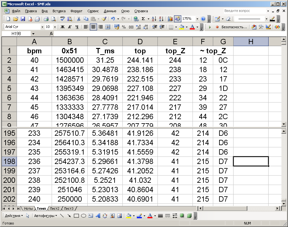
, , Excel. ( ).
, , . , . , , , .
1.cpp
#include <stdio.h> #include <windows.h> #include <string.h> #define SPACE 1 HANDLE openInputFile(const char * filename) { return CreateFile ( filename, // Open Two.txt. GENERIC_READ, // Open for writing 0, // Do not share NULL, // No security OPEN_ALWAYS, // Open or create FILE_ATTRIBUTE_NORMAL, // Normal file NULL); // No template file } HANDLE openOutputFile(const char * filename) { return CreateFile ( filename, // Open Two.txt. GENERIC_WRITE, // Open for writing 0, // Do not share NULL, // No security OPEN_ALWAYS, // Open or create FILE_ATTRIBUTE_NORMAL, // Normal file NULL); // No template file } void filepos(HANDLE f, unsigned int p){ LONG LPos; LPos = p; SetFilePointer (f, LPos, NULL, FILE_BEGIN); //FILE_CURRENT //https://docs.microsoft.com/en-us/windows/desktop/api/fileapi/nf-fileapi-setfilepointer } DWORD wr; DWORD ww; unsigned long int read32(HANDLE f){ unsigned char b3,b2,b1,b0; ReadFile(f, &b3, 1, &wr, NULL); ReadFile(f, &b2, 1, &wr, NULL); ReadFile(f, &b1, 1, &wr, NULL); ReadFile(f, &b0, 1, &wr, NULL); return b3<<24|b2<<16|b1<<8|b0; } unsigned long int read24(HANDLE f){ unsigned char b2,b1,b0; ReadFile(f, &b2, 1, &wr, NULL); ReadFile(f, &b1, 1, &wr, NULL); ReadFile(f, &b0, 1, &wr, NULL); return b2<<16|b1<<8|b0; } unsigned int read16(HANDLE f){ unsigned char b1,b0; ReadFile(f, &b1, 1, &wr, NULL); ReadFile(f, &b0, 1, &wr, NULL); return b1<<8|b0; } unsigned char read8(HANDLE f){ unsigned char b0; ReadFile(f, &b0, 1, &wr, NULL); return b0; } void message(unsigned char e){ printf("Error %d: ",e); switch(e){ case 1: // - -; printf("In track0 event is not FF\n"); break; case 2: // - 127 printf("Len of FF >127\n"); break; case 3: // ; printf("Midi is incorrect\n"); break; case 4: // ; printf("Delta>255\n"); break; case 5: // RPN NRPN; printf("RPN or NRPN is detected\n"); break; case 6: // ; printf("Note in 1...35 range\n"); break; case 7: // ; printf("Long of name of midi file >18\n"); break; } system("PAUSE"); } int main(){ HANDLE in; HANDLE out; unsigned int i,j; unsigned int inpos; unsigned int outpos=0; unsigned char byte; // ; unsigned char byte1; // 1 ; unsigned char byte2; // 2 ; unsigned char status; //- ( ); unsigned char sz0; // -; unsigned long int bsz0; // -; unsigned short int format, ntrks, ppqn; // ; unsigned long int bsz1; // ; unsigned long int bpm; // ( . ); unsigned long int time=0; // ( ); unsigned char scale; // , ; unsigned char oct; // ; unsigned char nt; // ; unsigned char outnote; // ; unsigned char prnote=0; // ; unsigned char tdt; // () ; unsigned int dt; // ( ); unsigned int outdelta=0; // ( ); unsigned char prdelta=0; // ; char fullname[30]; // ; char name[16]; // ; WIN32_FIND_DATA fld; // mid; HANDLE hf; unsigned short int csz; // ; unsigned char nfile=0; // ; unsigned char adr[128]; // ; out=openOutputFile("IMAGE.out"); outpos=512; // ; filepos(out,outpos); hf=FindFirstFile(".\\midi\\*.mid",&fld); do{ printf("\n***** %s *****\n",fld.cFileName); if(strlen(fld.cFileName)>18){ // ; message(7); } sprintf(name,"%s",fld.cFileName); name[strlen(fld.cFileName)-4]=0; // ; sprintf(fullname,".\\midi\\%s",fld.cFileName); // ; WriteFile(out, name, strlen(name), &ww, NULL); // ; in=openInputFile(fullname); // ; #include "process.cpp" // ; outpos+=((csz/512)+1)*512; // ; adr[nfile]=(outpos/512)-((csz/512)+1); // () ; filepos(out,outpos); CloseHandle(in); nfile+=1; }while(FindNextFile(hf,&fld)); // , ; FindClose(hf); WriteFile(out, &outnote, 1, &ww, NULL); outpos=0; // ; filepos(out,outpos); WriteFile(out, adr, nfile, &ww, NULL); outpos=511; // ; filepos(out,outpos); WriteFile(out, &nfile, 1, &ww, NULL); CloseHandle(out); system("PAUSE"); return 0; } Process.cpp file attachment
time=0; inpos=8; // ; filepos(in,inpos); format=read16(in); ntrks=read16(in); ppqn=read16(in); if(format!=1 || ntrks!=2 || ppqn!=48){ message(3); } inpos+=10; filepos(in,inpos); // -; bsz0=read32(in); inpos+=4; while(inpos<22+bsz0){ // ; tdt=read8(in); inpos+=1; // ; dt=(unsigned int)(tdt&0x7F); while(tdt&0x80){ tdt=read8(in); inpos+=1; dt=(dt<<7)|(tdt&0x7F); } byte=read8(in); inpos+=1; if(byte==0xFF){ // , - -; byte=read8(in); // -; sz0=read8(in); // , , 127 ( ); if(sz0&0x80){ message(2); } inpos+=2; switch(byte){ case 0x51: // "Set Tempo"; bpm=read24(in); scale=256-(bpm/(ppqn*128)); printf("scale=%d\n",scale); filepos(out,outpos+15); // ; WriteFile(out, &scale, 1, &ww, NULL); csz=16; break; default: break; } inpos+=sz0; filepos(in,inpos); // , 0x51; }else{ message(1); } } // ; outdelta=0; inpos+=4; filepos(in,inpos); bsz1=read32(in); inpos+=4; while(inpos<30+bsz0+bsz1){ tdt=read8(in); inpos+=1; // ; dt=(unsigned int)(tdt&0x7F); while(tdt&0x80){ tdt=read8(in); inpos+=1; dt=(dt<<7)|(tdt&0x7F); } outdelta+=dt; // ; // , , ; time+=dt; // ; byte=read8(in); // , ; inpos+=1; if(byte&0x80){ // ; status=byte; // ; if(byte==0xFF){ // -; byte=read8(in); // , ; sz0=read8(in); inpos+=(2+sz0); filepos(in,inpos); }else{ // ; byte1=read8(in); inpos+=1; } }else{ // , ; byte1=byte; } switch(status&0xF0){ // , ; case 0xF0: // , -; break; case 0x80: // ; byte2=read8(in); // ( ); inpos+=1; // , ; if(byte1>1&&byte1<36){ // ; message(6); } if(byte1>1){ // ; oct=((byte1-36)/12); // ; nt=(byte1-36)%12; // ; }else{ // ; oct=0; nt=15; } outnote=(oct<<4)|nt; // ; prnote=outnote; prdelta=outdelta; if(outdelta>255){ // 255 ( ); message(4); } WriteFile(out, &outdelta, 1, &ww, NULL); WriteFile(out, &outnote, 1, &ww, NULL); csz+=2; outdelta=0; // ; break; case 0x90: // ; byte2=read8(in); // ( ); inpos+=1; // , ; if(byte1>1&&byte1<36){ // ; message(6); } if(byte1>1){ // ; oct=((byte1-36)/12); // ; nt=(byte1-36)%12; // ; }else{ // ; oct=0; nt=15; } if(byte2){ // , ; outnote=0x80|(oct<<4)|nt; // = 1; // ; if(!outdelta && (outnote&0x7F)==prnote){ // ; prdelta-=SPACE; // -; filepos(out,outpos+csz-2); // ; WriteFile(out, &prdelta, 1, &ww, NULL); // ; filepos(out,outpos+csz); outdelta=SPACE; // - ; } }else{ // , ; outnote=(oct<<4)|nt; prnote=outnote; // ; prdelta=outdelta; // -; } if(outdelta>255){ // - ; message(4); } WriteFile(out, &outdelta, 1, &ww, NULL); WriteFile(out, &outnote, 1, &ww, NULL); csz+=2; outdelta=0; // - ; break; // () ; case 0xA0: // ; byte2=read8(in); inpos+=1; break; case 0xB0: // ; if(byte1>=98&&byte1>=101){ // NRPN RPN; message(5); // ; } byte2=read8(in); inpos+=1; break; case 0xC0: // (. ); // , , ; break; case 0xD0: //; break; case 0xE0: // ; byte2=read8(in); inpos+=1; break; default: // ( ); break; } } // 0xFFFF, ; outdelta=255; outnote=255; WriteFile(out, &outdelta, 1, &ww, NULL); WriteFile(out, &outnote, 1, &ww, NULL); csz+=2; // , ; printf("Length: %i (%i:%02i)\n",time,time/192,time%192); The basic part of the program for MK, in fact, is very simple. Consider one of the options for its implementation, more precisely, its main part.
Timer 1, used to generate note sound, is configured as follows. To enable and disable notes, use the following substitutions respectively.
#define ENT1 TCCR1B=0x09;TCCR1A=0x40 #define DIST1 TCCR1B=0x00;TCCR1A=0x00;PORTB.1=0 Before turning on the timer, you need to assign a 16-bit value to the OCR1A register, which will correspond to the reproduced frequency. This will be shown below. When the timer is enabled, the TCCR1B register is assigned the “Waveform Generation Mode” with a timer divider of 1, and the TCCR1A register is assigned to “Toggle OC1A on Compare Match”. In this case, the signal is removed from a specially assigned output of the MK "OC1A". In the ATmega8 in the SMD package, this is pin 13, which is the same as PORTB.1. When the timer is turned off, both registers are reset, and the PORTB.1 output forcibly becomes zero. This is necessary in order to prevent a constant voltage output during silence, which will be undesirable for ULF input. Although it is possible to put a capacitor in the circuit, it is also possible to disable the output programmatically. A constant voltage may occur on this pin if the note is turned off at the moment of the corresponding phase of the signal, which is 50% of the time.
Create an array of timer values for 12 notes of the very first octave. These values were calculated in advance.
freq[]={61156,57724,54484,51426,48540,45815,43244,40817,38526,36364,34323,32396}; The values of the notes of the other octaves, as I said, will be obtained by dividing by powers of two.
Timer 0 configuration is even simpler. He works constantly, with interruption on overflow, each time being initialized anew by the value that corresponds to the tempo of the melody. The timer divider is 5: TCCR0 = 0x05. Based on this timer, a virtual timer has been created that counts ticks (lengths of time) into a melody. The response processing for this timer is placed in the main program loop.
The timer interrupt function 0 looks like this.
interrupt [TIM0_OVF] void timer0_ovf_isr(void){ if(ent01){ vt01+=1; } TCNT0=top0; } Here the variable ent01 is responsible for activating the virtual timer. For this variable, you can enable or disable it, if necessary. The variable vt01 is the countable main variable of the virtual timer. The string TCNT0 = top0 indicates the initialization of timer 0 to the desired value of top0, which is read from the melody header before it is played.
The number of the melody to be played corresponds to the variable alm. It also serves as a flag for the start of playback. She needs to assign a melody number in one of the ways, depending on the task. After that, the next block of the main loop will become active.
if(alm){ // ; adr=eepr(alm-1)<<9; // (<<9 512); adr+=15; // , ; top0=eepr(adr); // ; adr+=1; // ; adr0=adr; // ( ); top01=eepr(adr); // " " ; adr+=1; // ; note=eepr(adr); // ; adr+=1; // -; vt01=0; // ; ent01=1; // ; TCNT0=0; // ; alm=0; // , ; } Further switching from note to note is carried out in the processing unit of the virtual timer, which is also placed in the main loop.
if(vt01>=top01){ // , ; vt01=0; // ; if(note&0x80){ // ""; nt=note&15; // ; oct=(note&0x7F)>>4; // ; if(nt!=15){ // 15, ; OCR1A=freq[nt]>>oct; // ; // ; ENT1; // ; }else{ // " " ; DIST1; // ; } }else{ // ""; DIST1; // ; } top01=eepr(adr); // " "; adr+=1; // ; note=eepr(adr); // ; adr+=1; // ; if(note==255 && top01==255){ // ; top01=eepr(adr0); // , ; note=eepr(adr0+1); // ; adr=adr0+2; // ; } } From the comments in the text of the program everything should be quite clear and understandable.
To stop the melody, the following insert of the main loop is applied.
if(stop){ // ; DIST1; // ; ent01=0; // ; vt01=0; // ; } There is a small note about the implementation of the playback of the melody. Before the start of each new note, the microcontroller spends a small amount of time converting the read byte of the note into the value of the timer value. This time, as it turned out in practice, is relatively short, and does not affect the quality of reproduction. But I had doubts that this operation would remain unnoticeable. In this case, there would be extra pauses before each note, and the rhythm of the melody would be broken. But this problem is also solved. It is enough to calculate the values of the timer of the next note in advance, while the current note sounds. This procedure for a specially designated flag must be performed separately from the processing of the virtual timer in the main program loop. Due to the fact that the calculation time is unlikely to exceed the time of sounding even the shortest note, this decision is appropriate.
We now turn to testing the program.
In addition to the above code snippets, I added the button handling functions to the MK program, with which I can control the on or off of a particular melody. The EEPROM is connected to the MC via I2C bus, the work with which is implemented at the program level. The project was done with the help of CodeVisionAVR together with CodeWizardAVR. The output of the MK from pin 13 is sent to the PC sound card through a divider and I record the sound of the melody in the sound editor. I flashed the EEPROM memory using software and hardware, which I wrote about in a previous article. Due to the fact that not all bytes of the image file are useful, the memory can be flashed only by useful bytes (until the end of the ring tones) in order to save recording time and chip life. To do this, you can make a separate program, or write bytes to the chip directly during the conversion, adding to the main program.
Among the eight melodies, there are three test ones, with the help of which I will estimate by ear the frequency range, the sound of merging identical notes, the sound of the shortest notes, the fast transitions, etc. Let me remind you that merging identical notes actually sound with a pause of one tick, and the first note in a merge lasts one tick less.
One of the test melodies is a sequence of notes from first to last with a one-quarter note lasting one quarter and a melody tempo of 40 bpm.
In this scenario, one note sounds a little more than a second, and therefore you can listen in detail how the whole range of notes sounds. On the frequency spectrum in the audio editor "Adobe Audition", the main frequency components and their upper harmonics are observed due to the corresponding sawtooth waveform. And also the logarithmic relationship between the note number and frequency is striking.
Analyzing the time intervals, it is clearly seen that the real pause between consecutive notes averages approximately 145 samples (at a sampling frequency of audio recordings of 44,100 Hz), which is about 3 ms. This is the time during which the MC makes the necessary calculations. These inserts are present regularly before each note. I specifically wrote the value in the samples, since this information is more original and more accurate, although this is not very important.
And the length of one tic with an average melody tempo of 120 bpm is about 10 ms. It follows that, in principle, it would be possible not to introduce the very amendment to 1 tick, when two identical notes go one after the other without a pause. I think that a regular insert in 3 ms between notes would be quite enough. When listening to the melody, these regular inserts are generally not noticeable, and the melodies sound exactly. Therefore, there is no special need to calculate the timer value for the next note while the current one sounds.
Another test melody with a tempo of 200 bpm contains identical 1/32 notes in a row from the middle range without a pause. In this case, after processing, during playback, there is a 1 tick pause between them, which is 310 samples (about 6 ms) of the recorded signal at this fast pace.
The length of this pause, by the way, is comparable to the period of the signal, which indicates a high tempo of the melody. And its sound is like a trill.
In principle, this can be finished. I was satisfied with the result of the device, it exceeded all expectations. Most of the time I spent studying the midi format and debugging the program for conversion. I will also devote one of the following articles to a topic related to midi, where I will be told about the use of this format in other interesting applications.
Source: https://habr.com/ru/post/454514/
All Articles