Hardware bit banding CortexM3 / M4 (ARM), kernel architecture, assembler, C / C ++ 14 and a drop of metaprogramming
Introduction
Attention, this is not another “Hello world” article about how to blink a LED or get into your first interruption on STM32. However, I tried to give exhaustive explanations on all the issues raised, so the article will be useful not only for many professional and dreaming developers (as I hope), but also for beginner programmers of microcontrollers, since this topic somehow comes along on countless sites / blogs "programming teachers MK."
Why did I decide to write it?
Although I exaggerated, having said earlier that the hardware bit banding of the Cortex-M family is not described in specialized resources, there are still places where this opportunity is covered (and even here I met one article), but this topic clearly needs to be supplemented and modernized. I note that this applies to English-speaking resources. In the next section, I will explain why this kernel feature can be extremely important.
Theory
(and those who are familiar with it, can jump immediately into practice)
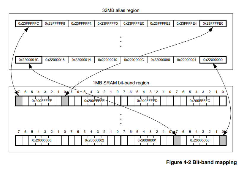
Hardware bit banding is a feature of the core itself, and therefore does not depend on the family and the manufacturer of the microcontroller, the main thing is that the core is suitable. In our case, let it be the Cortex-M3. Consequently, information on this issue should be sought in the official document on the core itself, and there is such a document, here it is , section 4.2 describes in detail how to use this tool.
')
Here I would like to make a small technical digression for programmers who are not familiar with assembler, of which most are now, due to the propagated complexity and uselessness of the assembler for such “serious” 32bit microcontrollers as STM32, LPC, etc. Moreover, you can often find censure for the use of the assembler in this area, even on Habré. In this section I want to briefly describe the mechanism for writing to the memory of the MC, which should clarify the advantages of bit banding.
I will explain on a concrete simple example for the majority of STM32. Suppose I need to turn PB0 into a general-purpose output. The usual solution will look like this:
GPIOB->MODER |= GPIO_MODER_MODER0_0; Obviously, we use a bitwise "OR" so as not to overwrite the other bits of the register.
For the compiler, this translates into the following set of 4 instructions:
- Download the general purpose register (RON) address GPIOB-> MODER
- Download to another RON values at the address specified in RON from P1.
- Make a bitwise "OR" of this value with GPIO_MODER_MODER0_0.
- Download the result back to GPIOB-> MODER.
Also, we must not forget that this kernel uses the instruction set thumb2, which means they can be different in size. I also note that everywhere we are talking about the level of optimization of O3.
In assembly language, it looks like this:
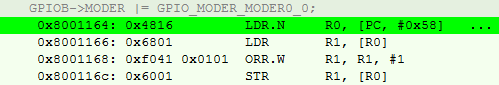
It can be seen that the very first instruction is nothing more than a pseudo-instruction with an offset; we find at the PC address (taking into account the conveying) + 0x58 value of the register address.

It turns out that we have 4 steps (and there are even more cycles) and 14 bytes of memory for one operation.
If you want to know more about this, then I recommend the book [2], by the way, is in Russian.
Moving on to the bit_banding method.
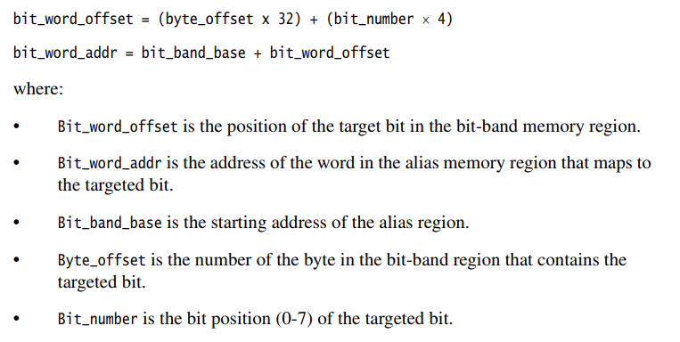
The bottom line, peasantly, is that there is a dedicated memory area in the processor, by writing values to which we do not change other bits of the peripheral register or RAM. That is, we do not need to comply with paragraphs 2) and 3), described above, and for this it is enough just to recount the address using the formulas from [1].
We are trying to do a similar operation, its assembler:

Recalculated address:

Here we added the instruction for recording # 1 in RON, but all the same, in the end, it turns out 10 bytes, instead of 14, and a couple of clocks less.
So what if the difference is funny?
On the one hand, the savings are not significant, especially in cycles, when it’s already a habit to overclock the controller to 168 MHz. On an average project, the moments where this method can be applied will be 40 - 80, respectively, in bytes, the savings can reach 250 bytes if the addresses differ. And if we consider that the programming of the MK directly on the registers is now considered a “zashkvar”, and it’s “cool” to use all kinds of cubes, then the savings can be much more.
Also, the figure of 250 bytes is distorted by the fact that high-level libraries are actively used in the community, the firmware is blown up to indecent sizes. Programming at a low level is at least 2 - 5% of software volume for an average project, with competent architecture and O3 optimization.
Again, I do not want to say that this is some kind of super-duper mega cool tool that every self-respecting programmer MK should use. But if I can cut costs even for such a small part, why not do it?
Implementation
All options will be given only to configure the periphery, since I did not come across a situation when it would be necessary for RAM. Strictly speaking, the formula for the RAM is similar, you just need to change the base addresses for the calculation. So how to implement it?
Assembler
Let's go from the bottom, with my favorite assembler.
On assembly projects, I usually allocate a couple of 2 bytes (according to the instructions working with them) RON for # 0 and # 1 for the whole project, and I also use them in macros, which reduces me to 2 more bytes on an ongoing basis. Remark, I did not find CMSIS on the Assembler for STM, because I immediately put the bit number in the macro, and not its value in the register.
Implementation for GNU Assembler
@ . MOVW R0, 0x0000 MOVW R1, 0x0001 @ .macro PeriphBitSet PerReg, BitNum LDR R3, =(BIT_BAND_ALIAS+(((\PerReg) - BIT_BAND_REGION) * 32) + ((\BitNum) * 4)) STR R1, [R3] .endm @ .macro PeriphBitReset PerReg, BitNum LDR R3, =(BIT_BAND_ALIAS+((\PerReg - BIT_BAND_REGION) * 32) + (\BitNum * 4)) STR R0, [R3] .endm Examples:
Examples for the Assembler
PeriphSet TIM2_CCR2, 0 PeriphBitReset USART1_SR, 5 The undoubted advantage of this option is that we have complete control, which cannot be said about further options. And as the last section of the article will show, plus this one is very significant.
However, no one needs projects for MK in Assembler, approximately from the end of zero, which means you need to switch to SI.
Plain c
Honestly, the simple Cishny version was found by me at the beginning of the path, somewhere in the vast network. At that time, I had already implemented bit banding in Assembler, and accidentally stumbled upon a C file, it immediately started working and I decided not to invent anything.
Implementation for plain C
/*!<=================PLAIN C SECTION========================>!*/ #define MASK_TO_BIT31(A) (A==0x80000000)? 31 : 0 #define MASK_TO_BIT30(A) (A==0x40000000)? 30 : MASK_TO_BIT31(A) #define MASK_TO_BIT29(A) (A==0x20000000)? 29 : MASK_TO_BIT30(A) #define MASK_TO_BIT28(A) (A==0x10000000)? 28 : MASK_TO_BIT29(A) #define MASK_TO_BIT27(A) (A==0x08000000)? 27 : MASK_TO_BIT28(A) #define MASK_TO_BIT26(A) (A==0x04000000)? 26 : MASK_TO_BIT27(A) #define MASK_TO_BIT25(A) (A==0x02000000)? 25 : MASK_TO_BIT26(A) #define MASK_TO_BIT24(A) (A==0x01000000)? 24 : MASK_TO_BIT25(A) #define MASK_TO_BIT23(A) (A==0x00800000)? 23 : MASK_TO_BIT24(A) #define MASK_TO_BIT22(A) (A==0x00400000)? 22 : MASK_TO_BIT23(A) #define MASK_TO_BIT21(A) (A==0x00200000)? 21 : MASK_TO_BIT22(A) #define MASK_TO_BIT20(A) (A==0x00100000)? 20 : MASK_TO_BIT21(A) #define MASK_TO_BIT19(A) (A==0x00080000)? 19 : MASK_TO_BIT20(A) #define MASK_TO_BIT18(A) (A==0x00040000)? 18 : MASK_TO_BIT19(A) #define MASK_TO_BIT17(A) (A==0x00020000)? 17 : MASK_TO_BIT18(A) #define MASK_TO_BIT16(A) (A==0x00010000)? 16 : MASK_TO_BIT17(A) #define MASK_TO_BIT15(A) (A==0x00008000)? 15 : MASK_TO_BIT16(A) #define MASK_TO_BIT14(A) (A==0x00004000)? 14 : MASK_TO_BIT15(A) #define MASK_TO_BIT13(A) (A==0x00002000)? 13 : MASK_TO_BIT14(A) #define MASK_TO_BIT12(A) (A==0x00001000)? 12 : MASK_TO_BIT13(A) #define MASK_TO_BIT11(A) (A==0x00000800)? 11 : MASK_TO_BIT12(A) #define MASK_TO_BIT10(A) (A==0x00000400)? 10 : MASK_TO_BIT11(A) #define MASK_TO_BIT09(A) (A==0x00000200)? 9 : MASK_TO_BIT10(A) #define MASK_TO_BIT08(A) (A==0x00000100)? 8 : MASK_TO_BIT09(A) #define MASK_TO_BIT07(A) (A==0x00000080)? 7 : MASK_TO_BIT08(A) #define MASK_TO_BIT06(A) (A==0x00000040)? 6 : MASK_TO_BIT07(A) #define MASK_TO_BIT05(A) (A==0x00000020)? 5 : MASK_TO_BIT06(A) #define MASK_TO_BIT04(A) (A==0x00000010)? 4 : MASK_TO_BIT05(A) #define MASK_TO_BIT03(A) (A==0x00000008)? 3 : MASK_TO_BIT04(A) #define MASK_TO_BIT02(A) (A==0x00000004)? 2 : MASK_TO_BIT03(A) #define MASK_TO_BIT01(A) (A==0x00000002)? 1 : MASK_TO_BIT02(A) #define MASK_TO_BIT(A) (A==0x00000001)? 0 : MASK_TO_BIT01(A) #define BIT_BAND_PER(reg, reg_val) (*(volatile uint32_t*)(PERIPH_BB_BASE+32*((uint32_t)(&(reg))-PERIPH_BASE)+4*((uint32_t)(MASK_TO_BIT(reg_val))))) As you can see, a very simple and straightforward piece of code written in the pre processor language. The main work here is the translation of CMSIS values into a bit number, which was absent as a need for an assembler version.
Oh yeah, use this option like this:
Examples for plain C
BIT_BAND_PER(GPIOB->MODER, GPIO_MODER_MODER0_0) = 0; // BIT_BAND_PER(GPIOB->MODER, GPIO_MODER_MODER0_0) = 1; // (!0) However, modern (massively, according to my observations, approximately since 2015) trends are in favor of replacing C with C ++, even for MC. And macros are not the most reliable tool, so the next version was destined to be born.
Cpp03
Here comes a very interesting and discussed, but little used in view of its complexity, with one hackneyed example of factorial, a tool - metaprogramming.
After all, the task of translating the value of a variable into the number of bits is ideal (there are already values in CMSIS), and in this case it is practical for compile time.
I implemented it as follows, using templates:
Implementation for C ++ 03
template<uint32_t val, uint32_t comp_val, uint32_t cur_bit_num> struct bit_num_from_value { enum { bit_num = (val == comp_val) ? cur_bit_num : bit_num_from_value<val, 2 * comp_val, cur_bit_num + 1>::bit_num }; }; template<uint32_t val> struct bit_num_from_value<val, static_cast<uint32_t>(0x80000000), static_cast<uint32_t>(31)> { enum { bit_num = 31 }; }; #define BIT_BAND_PER(reg, reg_val) *(reinterpret_cast<volatile uint32_t *>(PERIPH_BB_BASE + 32 * (reinterpret_cast<uint32_t>(&(reg)) - PERIPH_BASE) + 4 * (bit_num_from_value<static_cast<uint32_t>(reg_val), static_cast<uint32_t>(0x01), static_cast<uint32_t>(0)>::bit_num))) You can use the same:
C ++ 03 Examples
BIT_BAND_PER(GPIOB->MODER, GPIO_MODER_MODER0_0) = false; // BIT_BAND_PER(GPIOB->MODER, GPIO_MODER_MODER0_0) = true; // And why was the macro left? The fact is that I do not know of any other way to ensure that this operation is inserted without switching to another area of the program code. I would be very happy if the comments prompt. Neither templates nor inline features provide such a guarantee. Yes, and the macro here copes with its task perfectly well; there is no point in changing it just because someone who considers the
Surprisingly, time still did not stand still, compilers increasingly supported C ++ 14 / C ++ 17, why not take advantage of the innovations to make the code more understandable.
Cpp14 / Cpp17
Implementation for C ++ 14
constexpr uint32_t bit_num_from_value_cpp14(uint32_t val, uint32_t comp_val, uint32_t bit_num) { return bit_num = (val == comp_val) ? bit_num : bit_num_from_value_cpp14(val, 2 * comp_val, bit_num + 1); } #define BIT_BAND_PER(reg, reg_val) *(reinterpret_cast<volatile uint32_t *>(PERIPH_BB_BASE + 32 * (reinterpret_cast<uint32_t>(&(reg)) - PERIPH_BASE) + 4 * (bit_num_from_value_cpp14(static_cast<uint32_t>(reg_val), static_cast<uint32_t>(0x01), static_cast<uint32_t>(0))))) As you can see, I simply replaced the templates with the recursive constexpr function, which, in my opinion, is more understandable to the human eye.
Use the same. By the way, in C ++ 17, in theory, you can use the recursive lambda constexpr function, but I'm not sure that it will lead to at least some simplifications, and also will not complicate the assembler order.
Summarizing, all three C / Cpp implementations give an equally correct set of instructions, according to the Theory section. I have been working for a long time with all implementations on IAR ARM 8.30 and gcc 7.2.0.
Practice is a bitch
That seems to be the case. Memory savings calculated, the implementation chosen, ready to improve performance. It was not there, it was just a case of divergence between theory and practice. And when was it different?
I would never have published it if I hadn’t tested it, but to what extent the occupied volume decreases on projects. I specifically on a couple of old projects replaced this macro with a regular implementation without a mask, and looked at the difference. The result was unpleasantly surprised.
As it turned out, the volume practically does not change. I specifically chose the projects where exactly 40-50 such instructions were used. According to the theory, I should have saved at least 100 bytes, and at most 200. In practice, the difference turned out to be 24 - 32 bytes. But why?
Usually, when you configure peripherals, you configure 5-10 registers almost in a row. And at a high level of optimization, the compiler does not have instructions exactly in the order of the registers, but has instructions as it seems to him correct, sometimes interfering with them in seemingly inseparable places.
I see two options (here are my guesses):
- Or the compiler is so smart that it knows for you how it will be better to optimize the set of instructions.
- Either the compiler is still not smarter than a human, and he confuses himself when meeting such constructions
That is, it turns out that this method in high-level languages with a high level of optimization works correctly only if there are no similar operations in close proximity to one such operation.
By the way, at the O0 level, the theory and practice converge anyway, but this level of optimization is not interesting to me.
I summarize
A negative result is also a result. I think everyone will draw conclusions for himself. Personally, I will continue to use this technique, it will not be worse from him.
I hope it was interesting and I want to express the greatest respect to those who read to the end.
References
- Cortex-M3 Technical Reference Manual, Section 4.2, ARM 2005.
- The definitive guide to the ARM Cortex-M3, Joseph Yiu.
PS I have in stock a bag of little-lit topics related to the development of embedded electronics. Let me know, if interested, I will slowly get them.
PPS Somehow it turned out to be inserted into the code sections, please tell me how to improve, if possible. In general, you can copy the interesting piece of code in notepad and avoid unpleasant emotions when analyzing.
UPD:
At the request of readers, I indicate that the operation of bit banding itself is atomic, which gives us some security when working with registers. This is one of the most important features of this method.Source: https://habr.com/ru/post/454408/
All Articles