OOP in graphical programming languages. Part 2 MOP and OOP
In the first part I tried to show that the black cat of the PLO exists in the dark room of graphic languages, even if it is not a cat, but a half-dead cat of the Schrodinger flayer, which is, that is, it is not there. An example of the implementation of an object-oriented programming methodology was shown, when a program is not C ++ or Java code, but a Simulink, SimInTech, SimulationX or SCADE Esterel diagram, any graphic notation for describing an algorithm.
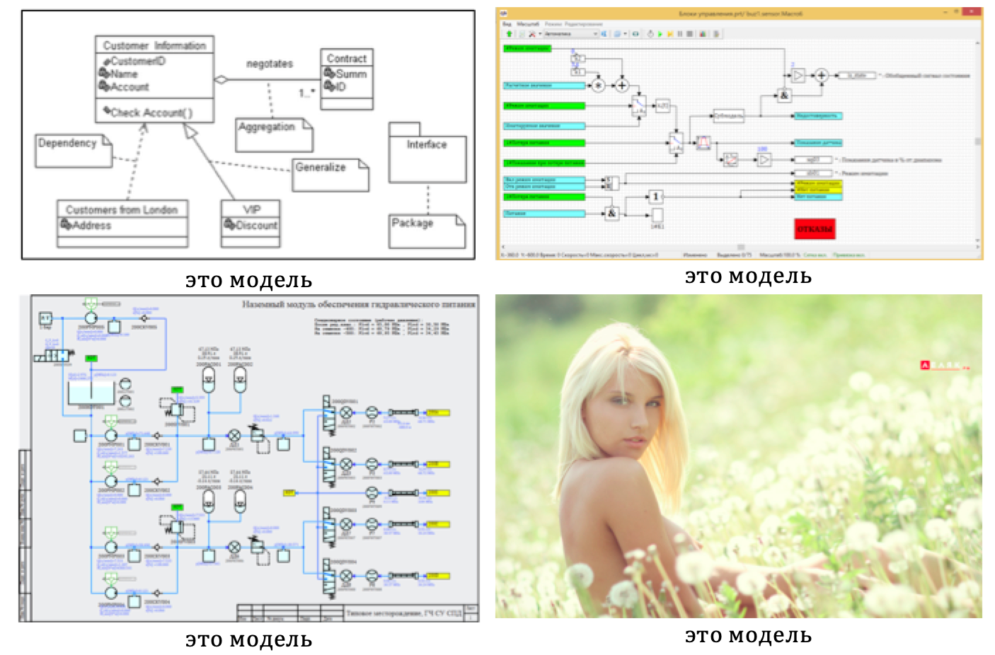
The promotional materials Matlab Simulink often use the term MOS - Model-Oriented Design (Model-based design). In many texts, they emphasize that the graphic scheme of the algorithm is a model, which, of course, is true. However, in the initial definition of the MOS, a model is first of all a model of an object to which a control system is developed, including control software. Thus, developing a control system according to the MOP methodology, it is possible and necessary to use the OOP methodology for developing control software. And to finally close the issue with the models, here's a picture of you with differences from one another. If everything is clear, then you can not continue to read.
Let's return to graphic languages and OOP with reference to managing programs for the industry. A graphical programming language provides for recording a program in the form of a circuit from a set of blocks connected by communication lines. As a rule, in industrial programming, code is generated for the compiler from the graphic scheme by the automatic code generator and then loaded into the target hardware.
As part of my specialty, I had to work with control software for NPPs, where safety standards prohibit using C ++, only pure C, and in some cases not even C, but “iron” logic, where algorithms are implemented as electronic circuits using transistors and relay. And the observance of standards is monitored by tough guys from supervisory authorities.

But even here, no matter how surprising it may sound, the development still goes on using the OOP methodology. Because when OOP can not be used, but really want, you can. True, then you need to bring everything back, and that there would be no C ++ and the resulting code, for the safety and standards of über alles. As the saying goes, eat fish and not sit down for violations.
To make a real object as defined by OOP, we link data structures and processing schemes into a single object, this is called encapsulation. And since we cannot use C ++ for reliable NPP systems, we must sort it all back when generating code. As explained in the comments to the previous article, the first C ++ Front compiler worked in the same way, translating OOP C ++ code into pure C.
In the first version of the implementation of the OOP in a graphical language, we created a special block containing a graphical design scheme. During initialization, this block tied the class scheme (method) to a specific “class instance” —a set of variables named in a special way.
Consider the second implementation of the OOP methodology in graphical programming languages. Figure 1 shows the scheme of the sensor processing algorithm.
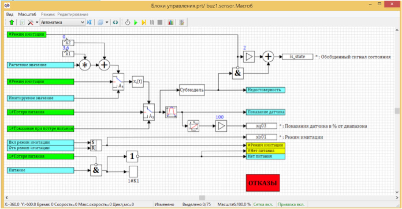
Figure 1. The processing of sensor readings.
This is a class method. It has its own category “Sensors” in the database - an abstract class with a given field set and an instance of the class KBA31CFO1 specific sensor. This field sensor has specific values, some of the fields are set by the user, some of the fields are calculated by the program execution process. see fig. 2

Figure 2. The signal database with the open category "Sensor".
So far, everything is the same as in the first version, where we have formed the binding of the design scheme to a specific sensor when installing the unit on the scheme. “Where is the difference?” You ask. And the difference is inside the block. If in the first variant there was a design scheme inside, which was copied with each installation of the block, then in this variant the inside looks like this:

Figure 3. The insides of a block diagram of a class instance.
Instead of the design scheme inside the block, only the transmission and reception of data is “shown”.
And the execution of the calculation itself takes place in another place, in the diagram from Figure 1. In some cases, it is possible not to use blocks at all on the design scheme, if there are enough instances of the sensor class in the database of signals. This is the second way to implement encapsulation in graphic languages. The point is that all the blocks in the diagram of Figure 1 are vector, and they process not one signal, but a vector of signals from all sensors of this type in the design diagram. If you turn on the mode of displaying the results on the communication line, then we will see that each communication line contains not one digit, but a vector of 4 numbers (by the number of sensors in the database).

Figure 4. Sensor signal processing circuit in the mode of viewing the values.
Thus, one processing circuit implements the processing of all sensors in a project, and each sensor is processed with its parameters specified in the database as characteristics of a particular class instance. For example, the limiter takes the maximum value from the database, which is set the same for the first three sensors and differs from the fourth one. (see fig. 5)

Figure 5. The parameters of the block limiter in the calculation scheme.
And what about the result code, which is automatically generated by this wonderful scheme, how can you avoid OOP artifacts? It's simple: no cheating and no OOP, in the code is pure C. For each block of the vector processing scheme, a cycle will be formed that provides as many calculations as there are instances of the class in the project. In our case, there are 4 sensors, so we first form arrays of dimension "4" by reading signals from the sensors:
/* Index=104 UID=104 GeneratorClassName=TSignalReader Name=buz1.sensor.Macro6.Macro3.Macro157.SignalReader3 Type= */ }; state_vars->kbastdv104_out_0_[0] = kba31cf001_mf_type; state_vars->kbastdv104_out_0_[1] = kba32cf001_mf_type; state_vars->kbastdv104_out_0_[2] = kba33cf001_mf_type; state_vars->kbastdv104_out_0_[3] = uf40y329084320_mf_type Then we sort all the blocks in order and start them in a loop. For each element of the array type, each computing unit will be executed for all sensors.
/* Index=211 UID=211 GeneratorClassName=TAndSrc Name=buz1.sensor.Macro6.And61 Type= */ for(i=0;i<4;i++){ locals->v211_out_0_[i] = state_vars->kbastdv125_out_0_[i] && (!(locals->v191_out_7_[i] > 0.5)); /* Index=212 UID=212 GeneratorClassName=TMulDbl Name=buz1.sensor.Macro6.Mul_oper1 Type= */ locals->v209_out_2_[i] = consts->kbastdv121_a_[i]*state_vars->kbastdv127_out_0_[i]; /* Index=213 UID=213 GeneratorClassName=TSumSrc Name=buz1.sensor.Macro6.Add_oper1 Type= */ locals->v209_out_3_[i] = (1)*consts->kbastdv122_a_[i]+(1)*locals->v209_out_2_[i]; … } After calculation, we write signals for each instance of the class:
/* Index=776 UID=776 GeneratorClassName=TSignalWriter Name=buz1.sensor.Macro6.Macro3.SignalWriter4 Type= */ kba31cf001_mf_xb01 = state_vars->kbastdv207_out_0_[0]; kba32cf001_mf_xb01 = state_vars->kbastdv207_out_0_[1]; kba33cf001_mf_xb01 = state_vars->kbastdv207_out_0_[2]; uf40y329084320_mf_xb01 = state_vars->kbastdv207_out_0_[3]; As you can see, there are no objects in the final code. Clean, innocent and safe SI. In the given example of the implementation of the OOP in a graphical language, the vector scheme calculates all the same type sensors. This technique allows you to change one scheme to change the processing of all sensors.
Another added benefit of this approach is error insurance. Imagine: you manually add a sensor and in one place you forgot to increase in the cycle the number of repetitions during processing. No static code analyzer will detect this error, the code is correct. And even at work it may not affect immediately and in an obvious way.
Well, in the end, the promised polymorphism and inheritance. In the first method, the user received many identical schemes that he could edit after installing the submodel block and, thereby, carry out polymorphism, changing the behavior of a specific instance of the class. I think everyone guessed that it is possible to change the processing scheme for a particular sensor, and we will get a new class, in which the fields match, but the methods are different. You can also add new fields and get a new class with different fields containing all fields of the parent and methods of the parent.
Figure 6 shows an example of two blocks of the “parent” and “heir” classes. Inside the block, the calculation scheme of the parent class is maintained. All data goes to a common vector block, similar to the block in Fig. 4. Completely repeated method of the parent class. And then the heir class has an additional field Yatm and an additional recalculation of the value using the linear interpolation block.
Thus, it remains possible to change the processing methods of the parent, which will change in all classes-heirs, as well as individually customize the behavior of the heir.

Figure 6. Polymorphism in class heirs.
Summing up, we can argue that the methodology of OOP can be used to create software in graphical programming languages. Abstraction, encapsulation, inheritance, polymorphism - all these principles are easily and naturally implemented with the right development tools. It is important to note that the final code, after automatic generation from a graphic language, remains pure safe C without any OOP
In some cases, the result of the development of control software, in graphical form, is not the C code for downloading to the controllers, but the electrical circuit diagram of the “iron logic”, but the method set forth above the PLO also works perfectly.
')
Source: https://habr.com/ru/post/454232/
All Articles