Two-digit thermometer

The author made this two-digit LED thermometer as a birthday present to his friend's son. He is only two years old, and he already reads the numbers, but he doesn’t. Now he can find out the temperature outside the window on his own. The sensor in the thermometer is a DS18B20 microcircuit operating according to the 1-Wire protocol, and the microcontroller is of the ATtiny84 type. The board is a square with a side of 25 mm, in size it is comparable to a 50 pence coin. The author plans to place the board in a waterproof case and place it outside the window. The display turns on briefly every 24 seconds, and the CR2032 battery lasts about a year.
The thermometer operates in the range of -19 to +99 ° C. If necessary, the minus and one are simultaneously displayed in the high-order digit. When out of range, the letters Lo or Hi are displayed. You can “teach” the device to display temperatures below -19 ° C, using the dotted segment as a minus.
According to this scheme, the device was pre-assembled on a breadboard:
')

All microcontroller pins are involved, the built-in clock generator at 8 MHz is used. The prototype turned out like this:
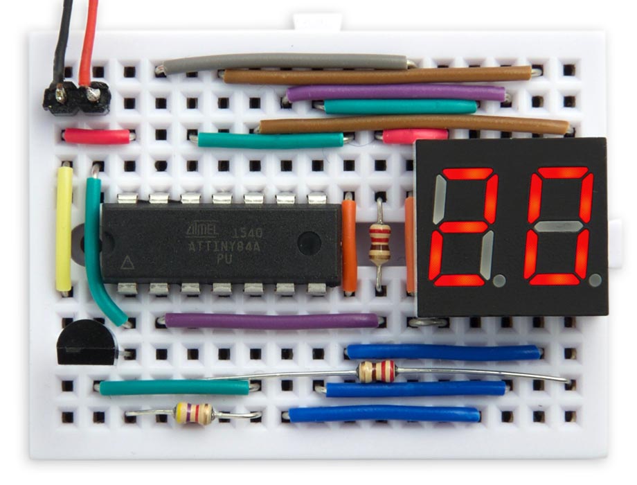
The prototype used the DS18B20 in the TO-92 package, the ATtiny84 in the PDIP package and a 3.6-inch 3621AS indicator. Then the author developed a board in Eagle and ordered it in PCBway. Here, the microcontroller is already in the SOIC package, the sensor is in the µSOP package, and the resistors, capacitors and display are of size 0805. Everything except the display is soldered with Youyue 858D + hair dryer at a temperature of 250 ° C.
Both on the prototype and on the printed circuit board, indicators with a common anode are used. The device is made in two versions, with indicators of red and yellow. Red - on KDPV, yellow - here:

A holder for a 20 mm lithium cell is soldered on the back side (any with a designation starting at 20, i.e., 2016, 2025 or 2032):

The firmware is written in such a way that the microcontroller is in sleep mode most of the time and wakes up due to an interrupt from the watchdog timer. This implementation of the same author is involved in the implementation of the 1-Wire interface. The 16-bit microcontroller timer counter, operating at a frequency of 1 MHz, is timed:
void OneWireSetup () { TCCR1A = 0<<WGM10; // Normal mode TCCR1B = 0<<WGM12 | 2<<CS10; // Normal mode, divide clock by 8 } The DelayMicros () subroutine provides a delay of a specified number of microseconds, based on the OCR0A output comparison register:
void DelayMicros (unsigned int micro) { TCNT1 = 0; TIFR1 = 1<<OCF1A; OCR1A = micro; while ((TIFR1 & 1<<OCF1A) == 0); } The routine DisplayTemperature () reads the temperature value from the sensor and displays it. Since there is only one sensor on the bus, you can ignore the serial number and simply issue the Skip ROM command, after which all subsequent commands go to any device:
void DisplayTemperature () { cli(); // No interrupts if (OneWireReset() != 0) { sei(); DisplayError(0); // Device not found } else { OneWireWrite(SkipROM); OneWireWrite(ConvertT); while (OneWireRead() != 0xFF); OneWireReset(); OneWireWrite(SkipROM); OneWireWrite(ReadScratchpad); OneWireReadBytes(9); sei(); // Interrupts if (OneWireCRC(9) == 0) { int temp = DataWords[0]; Display((temp+8)>>4); // Round to nearest degree } else DisplayError(1); // CRC error } } In response to a request, the sensor returns the temperature as a 16-bit signed integer in 1/16 degree units. The number is rounded to the nearest integer degree and displayed by calling the Display () subroutine.
The DisplayError () subroutine displays the errors of the microcontroller's interaction with the sensor via the 1-Wire bus:
void DisplayError (int no) { Buffer[0] = Error; Buffer[1] = no; } E0 - no sensor detected, E1 - CRC error.
Data for dynamic indication is taken from the array Buffer []. For example, to display the number 20, you need to run:
Buffer[0]=2; Buffer[1]=0; Timer counter 0 generates interrupts at a frequency of 125 Hz, which is enough to eliminate flicker. Initially, the timer is configured in setup () "
TCCR0A = 2<<WGM00; // CTC mode; count up to OCR0A TCCR0B = 0<<WGM02 | 4<<CS00; // Divide by 256 OCR0A = 250-1; // Compare match at 125Hz TIMSK0 = 0; // Interrupts initially off The matching interrupt handling procedure calls the DisplayNextDigit () subroutine and then counts down:
ISR(TIM0_COMPA_vect) { DisplayNextDigit(); Ticks--; } The DisplayNextDigit () subroutine reads data from the corresponding cell of the Buffer [] array and includes the necessary segments in the corresponding display bit. The program uses #define to select between an indicator with a common cathode or anode. If during the power supply all segments are lit at once, then the display type does not match the one specified in the firmware. For the common cathode, the subroutine should be replaced with the following:
void DisplayNextDigit () { PORTB = PORTB | 1<<digit; // Turn old digit off digit = digit ^ 1; // Toggle between 0 and 1 char segs = charArray[Buffer[digit]]; PORTA = segs; // Lit segments high PORTB = PORTB & ~(1<<digit); // Turn new digit on } Finally, the Display () subroutine generates a two-digit number to write to the Buffer [] array:
void Display (int n) { int units = n % 10; int tens = n / 10; int temp0 = tens; int temp1 = abs(units); if (tens < -1) {temp0 = Lo; temp1 = Lo+1; } else if (tens > 9) {temp0 = Hi; temp1 = Hi+1; } else if (tens == -1) temp0 = Minus1; else if ((tens == 0) && (units >= 0)) temp0 = Blank; else if ((tens == 0) && (units < 0)) temp0 = Minus; Buffer[0] = temp0; Buffer[1] = temp1; } It also takes into account the cases of displaying a minus along with the unit in the high-order bit, as well as reports of temperature out of range.
For the highest possible energy saving, the ADC, USI clock and ADC clock generators are disabled, and the PWR_DOWN sleep mode is enabled:
ADCSRA &= ~(1<<ADEN); // Disable ADC to save power PRR = 1<<PRUSI | 1<<PRADC; // Turn off clocks to USI & ADC to save power set_sleep_mode(SLEEP_MODE_PWR_DOWN); The main program displays the temperature for tenths of a second, then turns on sleep mode. It turned out that this is the minimum duration of the display, convenient for reading. Two seconds before the temperature is displayed, a dot flashes briefly:
void loop () { Buffer[0] = DP; Buffer[1] = Blank; DisplayOn(12); WDDelay(6); // Sleep for 1 second Buffer[0] = Blank; Buffer[1] = DP; DisplayOn(12); WDDelay(6); // Sleep for 1 second DisplayTemperature(); DisplayOn(12); WDDelay(9); // Sleep for 8 seconds WDDelay(9); // Sleep for 16 seconds WDDelay(9); // Sleep for 24 seconds } The display remains off for 24 seconds due to three watchdog calls of 8 seconds each. When the indicator is running, the current consumption is 6.6 mA, while in sleep mode it is 4.7 μA, the average current consumption is 1/240 * 6.6 mA. The typical capacity of the CR2032 element is 225 mAh, so it will suffice for (225 / 6.6) x 240/24 = 340 days - a little less than a year.
The temperature ranges of the components are as follows: the microcontroller and the indicator are from -40 to + 85 ° C, the resistors and the capacitor are from -55 to +125 ° C, and the batteries are from -20 to +70 ° C. The element with the extended temperature range BR2032 will operate in the range from -30 to +85 ° C.
The microcontroller is made Arduino-compliant with this Spence Konde development. In IDE, select ATtiny24 / 44/84 in the ATTinyCore section of the Board menu. Then you need to set the following options, regardless of the rest:
Chip: "ATtiny84" Clock: "8 MHz (internal)" BOD: "BOD Disabled" Pin Mapping: "Clockwise (like damellis core)" The program is flooded using the Pomona test clip, placed on top of the microcontroller and connected to the SparkFun Tiny AVR Programmer. First you need to select Burn Bootloader, then - Upload.
Links: the full text of the program , the board and the program on GitHub , the board on OSHpark .
Source: https://habr.com/ru/post/454220/
All Articles