MPPT charge controller on STM32F334C8T6
In the comments under my previous articles, the quite reasonable question has repeatedly arisen: "Why do dc / dc converters on a microcontroller when there are ready-made ones?" and I constantly mentioned as a response, as the most vivid example, the charge controller with the MPPT algorithm. But to say this is one thing, but to show ... it is already much more interesting and clearer, so today I will tell about my small sluggish project of such a controller.
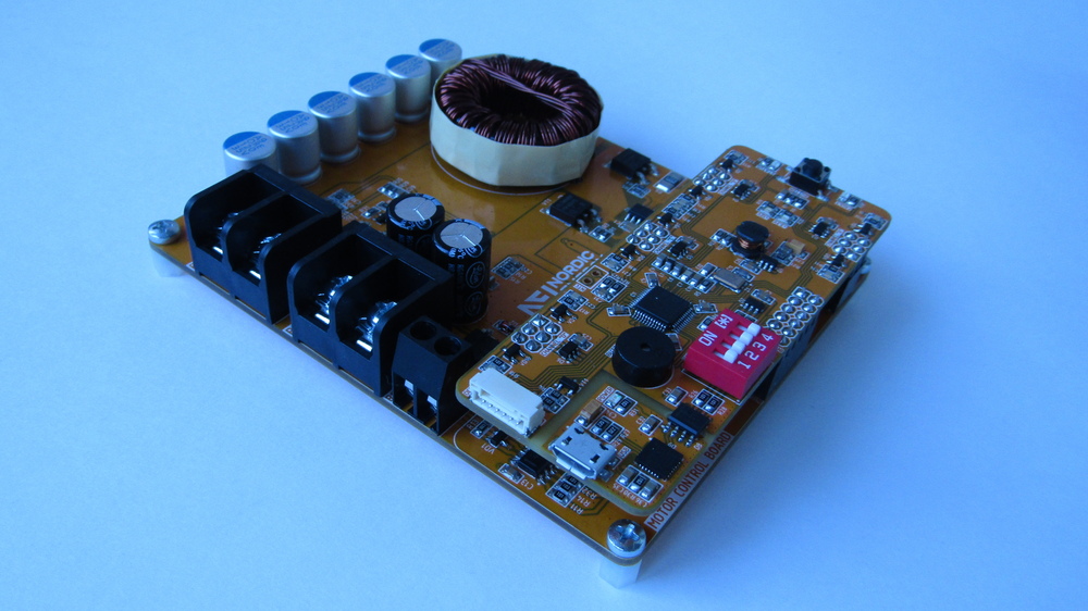
The controller project is open, all source files are available on github . The controller itself is quite simple to implement, it is built on the buck topology, the available components are used in it, and all this gives a good repeatability even without special knowledge. The layout of connectors and components is designed so that this controller can be used both as a debug board for studying power electronics, and as a ready device, it will just be to make a case for it.
Chapter 1. What is the MPPT algorithm and why is it needed?
Actually MPPT is the process of finding the maximum power point at the solar panel. The presence of this algorithm in the controller allows in certain conditions to significantly increase the efficiency of using solar panels. When the manufacturer writes power on the panel, for example, 100 ... 200 ... 250 ... 320 W, it means the nominal power of the solar panel at an insolation level of 1000 W / m 2 . Of course, manufacturers do not take out the panel on the street and do not wait for ideal weather conditions, so this value is accepted as standard and is “generated” on a laboratory bench.
Under actual conditions, under a clear sky, the maximum level of insolation ranges from 250 W / m 2 somewhere in Norway to 900-1000 W / m 2 in North Africa. From this it follows that in the North the solar panel will not give out its declared power, but in Africa it is easy. BUT ... As soon as clouds appear in the sky that obscure the solar panel, the level of insolation decreases. Remember the weather for the last month, how many perfect sunny days have you seen? If you are from Krasnodar, then perhaps a lot, but the residents of the middle band of clouds is definitely more.
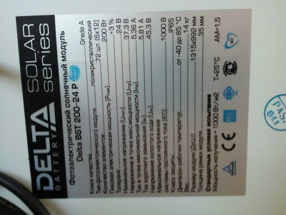
Actually, what's the problem ... When the illumination of the solar panel decreases, the location of the maximum power point (TMM) on the IVC of a real solar panel changes. Now let's see what TMM is ... To do this, we take a solar panel with a stated power of 200 W (I have this Delta BST200-24P) and remove from it a current-voltage characteristic (IVC) at an insolation level of 1000 W / m 2 :
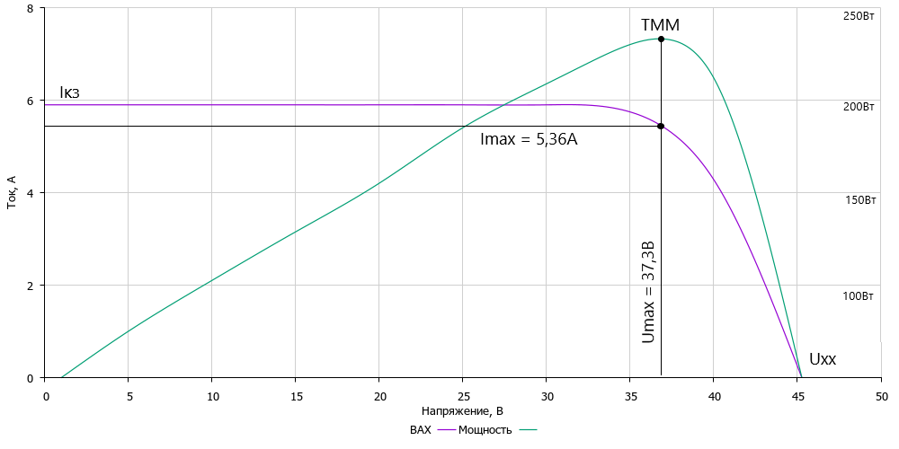
If you look at the power graph, then it clearly shows a peak in which the panel gives the maximum possible power - this is TMM. Also, if we lower the line down from this point, it will cross the IVC - the coordinates of this point are the very result that must be found. To put it simply: "MPPT is the process of searching for a point on the IVC in which the product of current and voltage has the maximum value"
Additionally, it is worth noting that the solar panel may produce a bit more, this is normal, because its efficiency depends not only on the level of insolation, but also on temperature. If you put the panel in the sun, then after a few hours it will heat up quite strongly and the power will drop by about 10%.
Now let's see what exactly the charge controller will do and why it needs an MRRT. As it was said earlier, the level of insolation will change significantly during operation: clouds, cloudy weather, dawn and sunset, respectively, the VAC of the solar panel will also change:
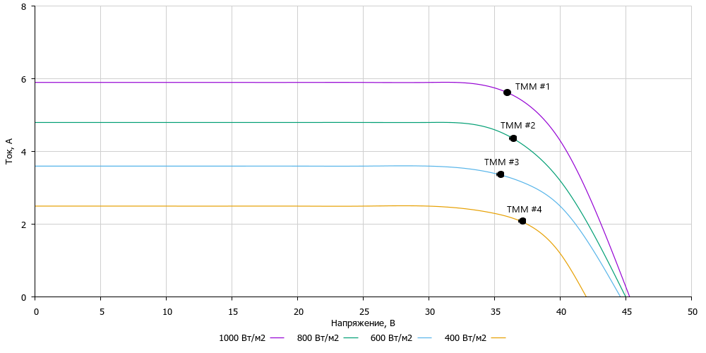
The graph shows the current-voltage characteristics for 4 cases: 1000, 800, 600 and 400 W / m 2 and, accordingly, for each case we will have our own point on the IV-curve, where the product of current and voltage will have the maximum value. The task of the charge controller with MPPT is to look for the maximum power point for specific weather conditions. For example, you live somewhere in Voronezh, you have warm and a lot of solar energy and you have found TMM and get the most power output, but after 15 minutes a cloud rose over your panels and partially covered the panels and the insolation value changed, and therefore the IVC changed panels. In order for the charge controller to adapt to the new conditions, it needs with some frequency, for example, once every 5 minutes, to make calculations and search for TMM for the new IVC.
There are many search algorithms for TMM, ranging from the simplest "0.8 * U xx " to various scanning algorithms with neural networks, but I will tell you more about the algorithm and their implementation in code in a separate article. I hope you understand what TMM is and why we are looking for it, now you can go directly to the gland.
Chapter 2. Technical characteristics and functionality of the controller
Now it is necessary to decide what the controller should be able to provide the necessary functionality. First, the controller charges the battery, and therefore it is necessary to implement CC / CV control (current and voltage stabilization) at the output and for this you need to measure the current and voltage at the output. Secondly, to search for TMM, it is necessary to measure the IVC of the solar panel, which means that it is necessary to measure the current and voltage at the input. Thirdly, there should be a lowering dc / dc, which will lower the input voltage to 12 or 24V, in this case it will be a synchronous buck. All this will allow to realize the main functionality of the device, as a result, the functional diagram will look like this:
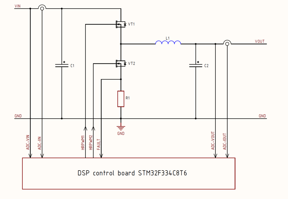
As you can see, there is nothing complicated, the scheme is very similar to the example from this article and the difference is only in additional feedback circuits for implementing the TMM search algorithm and the charging process. In addition, it is necessary to implement protection against overheating, from through currents, add a couple of interfaces to communicate with the outside world and conveniently update the firmware.
Specifications:
- Input voltage: 15 ... 60V
- Output voltage: 12 / 24V
- Rated output current: 20A
- Algorithms MRRT: yes
- Conversion frequency: 100 kHz
- Overheat protection: yes
- Through current protection: yes
- Battery Protection: OVP and OCP
- Interfaces: USB, Modbus
- Resource: at least 50,000 hours
- Overall dimensions: 1109020 mm
There are no special delights in this solution, the main bias is on increased reliability, efficiency of TMM algorithms and preservation of the controller's adequate cost. From the convenience it was decided to lay a galvanically isolated USB for setting up and flashing the control microcontroller + it can be used for debugging, if you do not like SWO. Also for the implementation of remote control and monitoring laid RS-485, which is reliable, cheap to implement and allows you to organize communication over a distance of 1000 meters. From wi-fi and other radio refused immediately, because the controller is usually operated in a metal shield and, as an option, in a reinforced concrete building.
Chapter 3. Selecting Components
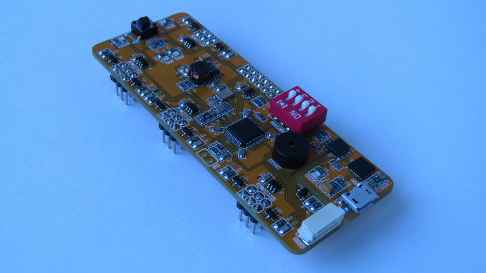
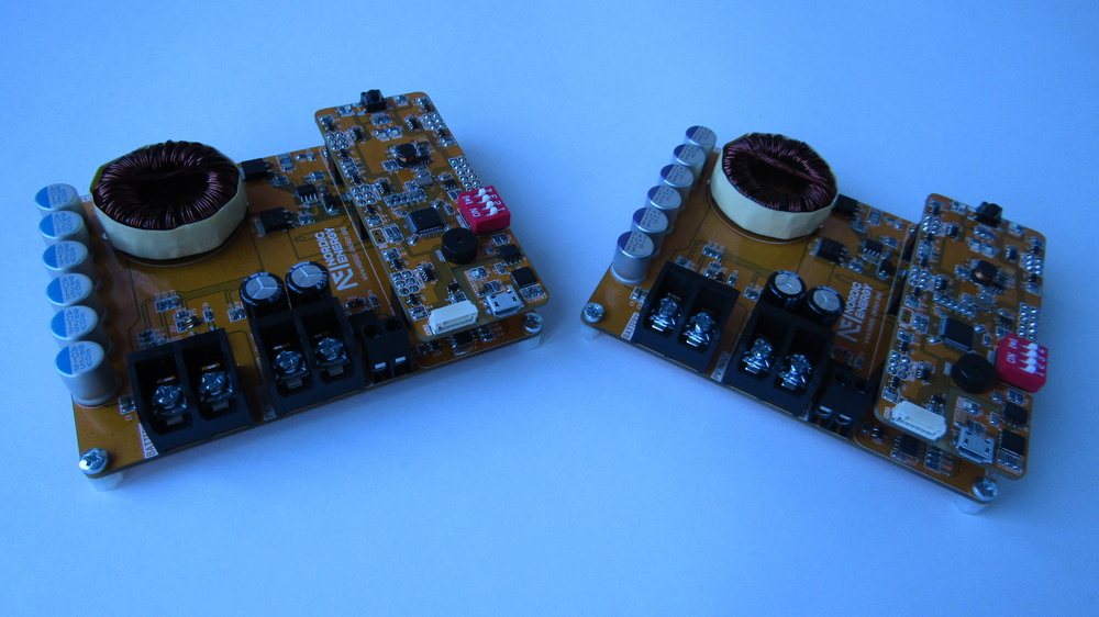
At KDPV, you can see that the device consists of two printed circuit boards: a 4-layer control module and a main 2-layer board. Attentive may notice that the control module is similar to the solution from the previous article , only thoroughly revised. Indeed, after testing the previous version of the control board and after discussions in the comments, it was decided to make a number of global changes:
- Refusal of vertical installation in the connector and the transition to the horizontal. This allowed to solve the problem with the connector and get by with the usual 2.54 mm PLS, as well as significantly reduce the height of the device. With the vertical version, the height of the controller would be 60 mm, not 20 and there would be a great chance to break the control board. Now she does not act on the background of the other components and still takes up little space;
- Board dimensions reduced to 90x35 mm;
- Controller STM32F334R8T6 replaced by a more compact and cheaper STM32F334C8T6. This replacement also led to a decrease in the number of channels for controlling the half-bridge from 5 to 4. As practice has shown, this controller does not take out control at once by the 5th half-bridges, except for quite simple algorithms. Based on this, it was decided to abandon the LQFP-64 package in favor of the LQFP-48;
- Added galvanically isolated USB, or to be more precise, the USB-UART bridge, since in the microcontroller there is no hardware USB interface;
- The PHY for RS-485 chip has been removed from the control board, since Not everyone needs it and not always, but for its possible use, the UART and an additional gpio for controlling the reception / transmission are output to the connector. Also now you can put a galvanically untied PHY on the main board and not be tied to my chosen solution;
- In addition to the SWD interface, it was decided to bring the SWO to the debugging connector for more convenient debugging of the program.
We now turn to the selection of components for the main (power) part of the converter. In my previous story about the Buck topology, I told about the choice of power components (transistors, capacitors, choke) and about the method of calculating their nominal values. Today I would like to tell a little more about the equally important components, namely about the driver for controlling the power switches, current sensors and so on.
Current sensor
To control the battery charge and measure the IVC of the solar panel, it is necessary to measure the direct current in the range from 0 to 20A. There are not so many options to measure direct current, the most effective and simple ways are the current shunt and the Hall effect sensor. In the first version, I tried a bunch of "shunt + INA194", the option is generally working, but the monitor itself was quite noisy and there was a problem in measuring currents less than 3-4A. The problem was solved by an increase in the nominal value of the shunt and a digital filter, but then the power released by the shunt in the form of heat increased, which was not much what it wanted.
Initially, the option of using Hall sensors, I threw back immediately, namely the ACS series (for example, ACS758 or ACS711), because In the past, he tried to use them, but they lied heavily and their measurement band was low. True, in one of the discussions, the person spoke about the successful experience of using these sensors, it turned out that the relatively new series stopped responding to the slightest pickup, the main thing is that there is nothing iron about them or anything that can be magnetized. I need to measure the direct current in the system, where the rate of change of the current is not high, and hence the 100 kHz band is enough. Based on the simplicity and price of the solution in the second version of the MPPT controller, I set the ACS713ELCTR-30A. Allegro has two versions of sensors - DC and DC / AC, I do not need to measure the switch, and therefore the choice is obvious in favor of DC, which also have a greater value of "volts per ampere". This made it possible to accurately measure not only large current values, but also small ones at a level of 0.3 ... 0.5A with a real error of ± 5%. The wiring of this sensor is extremely simple:
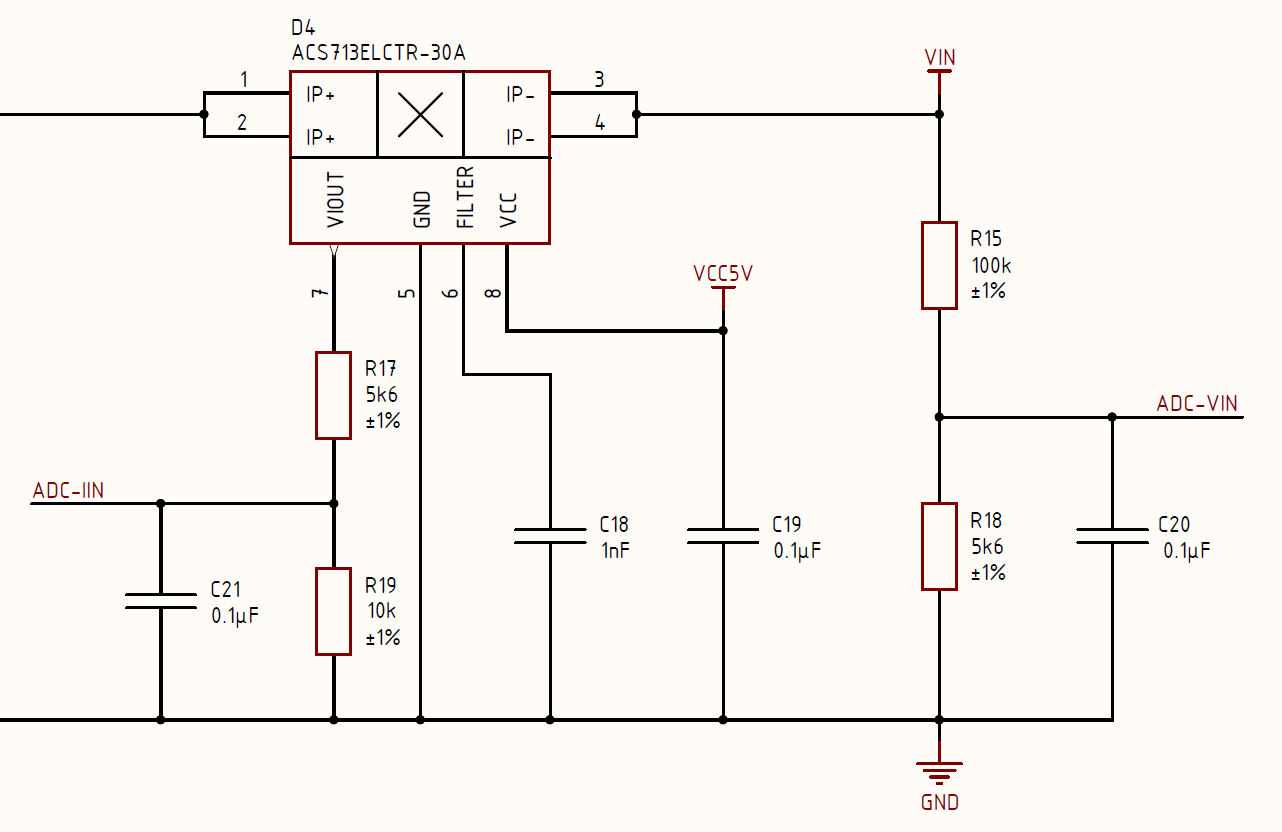
The inclusion is standard, there is no magic in the circuit, the only thing that needs to be done is to “match” the output range of the sensor 0 ... 5V with what the ATM microcontroller of the STM32 microcontroller can measure, namely with the range 0 ... 3.3V. At the sensor output voltage, it is linear and an increase in output voltage of 133 mV means an increase in the current flowing through the sensor by 1A. Based on this, the minimum voltage at the output is 0V, and the maximum 30A * 133 mV / A = 3.99V. Theoretically, the voltage divider could not be set, because The maximum current is only 20A and therefore the output voltage will be within 2.66V and does not threaten the ADC input, but it is better to be safe. Perhaps after testing and long running in the device, I still remove the divider and put a voltage follower on the op-amp.
Transistor gate driver
Even at the idea stage, I decided to immediately abandon the complete galvanic isolation of the control circuit from the power circuit, it is trivially expensive, although it eliminates interference and protects the digital part. The introduction of galvanic isolation of 2 voltages and drivers would increase the price of the converter by 40%. Therefore, my favorite Infineon 1ED / 1EDI drivers had to be abandoned and I chose something decent with bootstrapped power for the upper key, my choice was a fairly new solution - NCP5183DR2G. The driver proved to be very stable and sufficient to control a pair of mosfet-s at a frequency of 100 kHz. I found one minus in it - the lack of a separate input, for example, ShutDown or Enable to turn off the driver in case of an accident, so to implement protection, you need to set additional discrete logic or use the FAULT hardware input in the STM32F334 microcontroller itself. I chose the second option and so far he did not let me down, although initially I was skeptical about the reliability of such a solution. The transistor control circuit looks like this:
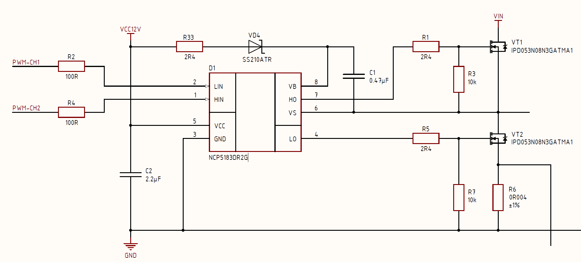
The solution is simple and straightforward, the only thing I will add is that the C1 capacitor must be ceramic with X7R dielectric and preferably not the nastiest, the original Yageo / Murata / Samsung is enough for everyone. The rest of the distribution can also be a simpler brand. By the way, you can read about this "torment of choice" of the nominal gate resistors R1 and R5 in this article .
Output capacitors
Above, I stated the priority of reliability and resource of the converter, and therefore it is necessary to eliminate all weaknesses. In modern dc / dc converters, in my opinion, there is one weak point left - electrolytic capacitors, which somehow dry out and degrade in some way, which leads first to increased pulsations and overheating, and then to the output of the converter.
There are 2 such places in my charge controller: input and output capacitors. It was decided to replace the output electrolytes with solid-state polymer capacitors (as in your video cards), which transfer work on currents of tens of amperes much easier and have a resource that is an order of magnitude higher than that of the highest-quality electrolytic capacitor. They have one minus - the price, this pleasure from Panasonic costs $ 2 / piece, but it's worth it.
At the input of the device, the voltage can reach 60V, which means that solid polymer capacitors can no longer be supplied, they simply do not, a maximum of 35V. True, there are hybrid options, this is an intermediate link between the electrolyte and the solid-state capacitor, they are up to 100V. In this type of capacitor, the liquid electrolyte is replaced with a pastelike one, which makes it possible to increase its resource at times.
The most attentive may notice that the output solid-state capacitors are different on the two boards. I think that everyone “appreciated” the cost for a 120 μF 35V capacitor, the electrolyte from Wurth is 10 times cheaper. Based on this, I decided for tests to buy an alternative to Panasonic 35SEK330M capacitors. Well, as an alternative ... there is such an Asian company Lelon , which makes a complete analog (from their words) capacitors from Panasonic. I put the original on one board, on another analogue, the devices themselves have already been tested for about a month and until the difference is really noticed, let's see what the final resource will be, but for those who want to drop the price 5 times to $ 0.4 / piece I advise you to think about.
Component overview
I would like to speak separately about the policy of choosing components and solutions. Since the idea involves using this controller not only for studying on the table, but also working "in the field", it was decided to use only proven manufacturers and not use Chinese components (except for the experience with Lelon ) and various crafts with aliexpress. In my version and in the BOM-e originals appear with digikey from manufacturers such as Infineon, TI, ON, ST, Yageo, Bourns and others. In principle, no one forbids you to put components simpler, with the same aliexpress, but be prepared to reduce the reliability and efficiency of the controller.
Chapter 4. About the project and source
I already wrote about power components and calculation methods in my article about the buck , you can read it here. I just give the results that I have turned out:
The inductance of the power choke is 30 μH, wound on the R32 / 20/10 ring from Kool Mu. Ring frankly with a margin chosen because experiments were planned with frequency and current increase;
The capacity of the output capacitors is about 300 microfarads, in reality the capacity is much larger, which reduced the output pulsations. I tried the work with 3 capacitors, everything is fine, so if you decide to repeat, feel free to leave half the seats under the output capacitors empty. In principle, you can try to solder 6 conventional electrolytic capacitors, if you can not buy solid-state. According to my assumptions, the controller will work without any problems;
Transistors ( IPD053N08N3GATMA1 ) I chose the ones that I had in stock and are fairly easy to buy. If you already have the keys or could not buy the ones that I have, then choose a transistor with a channel resistance of no more than 8 mΩ and a gate of no more than 100 nC. Otherwise, the efficiency will fall quite strongly and the transistors will significantly overheat.
Also, for sure there will be those who are too lazy to go to github, so I will leave the complete device diagram in PDF format:
The iron part of the project is made in Altium Designer 19, the project can also be opened in Curcuit Studio. For those who do not want to mess with the purchase of software or piracy, there is a schematic diagram in PDF and Gerber-files, this will be enough for you to order printed circuit boards by yourself and assemble the MRRT controller.
Now, as for the software ... In the near future, I will "brush" the test project on which the controllers are now working and also lay out on github, everyone will be able to see the implementation of various modules, and maybe help in writing it and searching for errors. I also plan a couple of articles on the software part of the dc / dc converter control, namely about P-, PI-, PID-regulators, their implementation, digital filters and, accordingly, about TMM search algorithms.
Conclusion
In the following, another revision of iron is assumed, since in the process of work, small but unpleasant trifles got out, for example, with some probability without firmware, a log.1 may appear on the MK's leads and it will open both transistors and lead to a short circuit. This problem is overcome either by pre-filling the firmware before first turning on the controller or a more correct way - installing 10 kΩ resistors that pull up the HIN and LIN inputs to ground (GND). Although in the current state the controller is operational, but I want to further "clean out" all potentially problematic places.
As always, I would like to thank PCBway for providing the printed circuit boards and stencils that were used during the prototype assembly process. Also a special thank you to everyone who used the button for donations, I'm going to drink your support will be spent on iron and this will translate into some interesting article.
I also have 2 sets of printed circuit boards left, if someone wants to assemble a controller, then I will donate to good hands. From you only need to collect and if you wish, then write me your comments and suggestions. Those who wish to write in a personal.
')
Source: https://habr.com/ru/post/454024/
All Articles