Comparison of cellular repeaters. RF-Link 1800 / 2100-75-23 and AliExpress Noname
For comparison, selected models of identical characteristics. Aliexpress Yellow Noname and RF-Link 1800 / 2100-75-23 - according to the passport both amplify the 1800 and 2100 MHz bands by 75 dB and have an output power of 200 mW (23 dBm). An important note in the article does not consider the price difference, yes it is, the article compares the real characteristics of the repeaters.
Theory
The types of modulation used in modern communication media place high demands on the linearity of the receive and transmit paths. These requirements also apply to repeaters, because the repeater becomes part of the system, an intermediary between the base station and the mobile terminal of the subscriber, and the quality of the components, the amount of interference and problems for the user that the repeater will create depend on the knowledge and experience of the development engineers. in the case of non-compliance with certain requirements in the development and production of which will be discussed below.
What is a repeater? If simplified, this is a bidirectional bandpass linear amplifier. In fact, this is a complex electronic device that must meet stringent requirements.
The main functional purpose of a radio frequency amplifier is to increase the level (range of oscillations, amplitude or power) of the input signal without unacceptable distortion of its shape, spectral composition, deterioration of the signal-to-noise ratio. In practice, it is impossible to obtain an undistorted signal at the amplifier output. This is explained by the fact that the amplifier includes active and passive elements that make their negative contribution, generating distortions.
Active elements include low-noise and intermediate (cascaded) amplifiers, electronic attenuators, output transistors, signal level detectors. Passive elements include duplex and bandpass filters, capacitors, inductors.
Linear and nonlinear distortions and their effect on signal quality
Linear distortions include the non-uniformity of the amplitude-frequency characteristic (AFC). The source of linear distortion are duplex and bandpass filters. Irregularity of the frequency response depends on the quality of their manufacture. The non-uniformity of the frequency response also has a significant influence on the degree of matching of all elements in the gain path from the input to the output connector, the layout of the elements, and the screening of the amplification stages. In order for the amplifier in the operating frequency band not to introduce linear distortion, its frequency response must be rectangular, and the phase-frequency characteristic (phase response) must be linear.
Nonlinear distortions include compressional distortions, second- and third-order intermodulation distortions, and signal phase distortions.
Sources of nonlinear distortion are active components, electronic attenuators, low-noise amplifier (LNA), intermediate stage amplifier chips, output transistors operating in the saturation mode, signal level detectors.
To minimize nonlinear distortion and maintain the amplifier in a linear mode, an automatic input level control (AGC) circuit is introduced into the amplification path. Its task is to compress the dynamic power range of the input signal, and to maintain the amplifier near the saturation point.
There are various ways to quantify the linearity of a power amplifier. The third-order intercept (IP3) is a well-known characteristic of an amplifier. The method is based on a two-tone test. Since modern communication systems create very complex signals, the relatively simple measurement of IP3 is often not suitable as an indicator for the required linearity. In addition, the standards do not define IP3 measurement requirements. To assess the quality of the signal with digital modulation at the repeater output, such indicators as the error vector vector module (EVM) and the power leakage ratio to the adjacent channel (ACLR) are used. An increase in linear and non-linear distortion leads to a decrease in ACLR and an increase in EVM.
Error Vector Module (EVM)
EVM is an important indicator of the quality of signals with digital modulation, expressing the difference in amplitudes and phases of the measured and ideal signals. It is expressed as a percentage. A very small EVM value means that the signal being tested is almost completely identical.
the original one.
For WCDMA, 3CPP defines the maximum EVM limit as 12.5% for a modulated signal of 16QAM and 17.5% for QPSK.
For OFDM, 3CPP defines the maximum EVM limit as 12.5% for a modulated signal of 16QAM, 8% for 64QAM and 17.5% for QPSK.
Adjacent Channel Power Leak Ratio (ACLR)
Adjacent Channel Power Factor (ACPR)
These parameters are used to estimate the degree of distortion caused by the non-linearity of amplifiers.
For WCDMA, the 3GPP specification describes minimum limits for the first and second adjacent channel. For the first it is -45 dB, for the second it is -50 dB.
For OFDM, the 3GPP specification describes a limit of -44.2 dB.
An increase in linear and non-linear distortion leads to a decrease in the ACLR value and an increase in EVM.
Testing a repeater implies:
- measurement of the OBW frequency band that it amplifies,
- measurement of frequency response
- measurement of the power leakage ratio to the adjacent ACLR channel or the power factor in the adjacent ACPR channel,
- EVM error vector measurement,
- measurement of intermodulation products.
Sample One - Yellow Repeater (Aliexpress Classic)
Cost up to 10 000 rubles.
Contents of delivery:
- Repeater;
- Power Supply;
- Packing box;
- Instructions.
Passport options:
- Frequency range: 1800 \ 2100;
- Gain: 75dB;
- Output power: 23dBm + -3dBm;
- Noise level: less than 5 dB;
- Wave resistance: 50 Ohm;
- Power supply: AC 110-220v, DC 5-12V.

Appearance of a repeater.
')

The appearance of the indicator.
- There are no controls on the case;
- From the means of visual control over the operation of the repeater, there are: three LEDs and a six-segment LCD indicator of the output signal level;
- Red LED indicates the presence of supply voltage;
- Two green indicators show the presence of a signal at the output of the Downlink 1800 and Downlink 2100 amplifiers;
- When the input signal level is about -75 dBm, the LEDs flash, at levels above -60 dBm, they are constantly on;
- Segment LCD indicators more accurately display the output level of each of the downlink channel amplifiers;
- Monitoring and indication of Uplink channels is not provided;
- There is no indication of overload on the amplifiers of the repeater.
Let's see what's inside.

The simplest budget option.
Four amplification stages in both directions.
SAW filters after each amplification stage.
Duplex filters on bulk dielectric resonators.
Amplifiers of different ranges combined adders.
The repeater has a built-in buck-down DC-DC converter, which reduces the risk of a repeater failure if an external power supply fails.

The screen is mediocre.
The repeater is symmetrical, the output power is the same in the descending and ascending channels.
Collected carefully. Automated soldering. The fee is clean, without flux residues.
In general, nothing interesting. The typical representative of the lowest price category.
Minuses
There is no automatic adjustment of the output level (ALC).
No manual gain control.
Signal level indicators in Downlink channels only.
The output level detector diodes are connected directly to the stripline after the output amplifier chip (intermodulation source).
Measurements
Frequency response of the channel Downlink 1800

With an input level of -60dBm, the maximum output level is 0.28dBm.
The minimum gain is 49dB.
Irregularity of the frequency response in the band 1805-1880 MHz slightly more than 11dB.
The maximum gain of the channel is 60dB (according to passport 75), taking into account the non-uniformity of the frequency response in the sections of 1805-1831 MHz and 1857-1880 MHz, it turns out even less.
Frequency response of the channel Downlink 2100

With an input signal level of -60 dBm, the maximum gain is 69.5 dBm (and on passport is 75).
The minimum gain is 62.1 dB. Irregularity of the frequency response in the band 2110-2170 MHz slightly more than 7 dB.
The amplitude-frequency characteristic of the channel Uplink 1800

With an input signal level of -60dBm, the maximum gain is 58dB. The minimum gain is 40dB. Irregularity of the frequency response in the 1710-1785 MHz band is slightly more than 18 dB! On the 1750-1785 MHz section, the 13dB is uneven.
The amplitude-frequency characteristic of the channel Uplink 2100

With an input level of -60dBm, the maximum gain is 56dB. The minimum gain is 49dB. Irregularity of the frequency response in the band 1920-1980 MHz about 7 dB.
Downlink 1800's maximum gain is 10dB less than Downlink 2100.
Further, power measurement and evaluation of linearity and distortion of the amplifier will be made using a wideband input signal. 5mHz signal band. QPSK modulation.
Downlink 1800 Maximum Output Power
Input level -53dBm.


Output undistorted power (RMS) is only 8.6 dBm. Peak power is 11.5dBm.
When declared by the manufacturer power 23dBm + -3dB.


Distortion in the channel.
Now increase the input level by 3 dB.


The power (RMS) increased to 12 dB, the peak power (PEAK) to 15 dBm, but there was an unacceptable power leakage to adjacent channels.
Accordingly, the signal distortion unacceptably increased.
At the same time, the output level indicator did not reach the maximum value (one division remained).


Signal constellation crumbled. The peak value of the modulation vector error exceeds 32% (the norm is up to 15%). The amplifier went into saturation mode, the 2nd and 3rd order intermodulation products appeared at the output of the amplifier.
For example: imitation of the work of two base stations. Frequencies 1820 MHz and 1865 MHz, 5 MHz signal bandwidth. QPSK modulation.
The signal level at the repeater input is 3dB and 5dB higher than the nominal one.
Intermodulation products in Uplink 1800 at a frequency of 1730 and 1775 MHz, with a level of 0dBm and + 6dBm.


Intermodulation components, getting into the Uplink channel, interfere with the base station direction, which leads to interruptions of communication, reduction in speed or inability to establish communication in general. It is also possible claims from the operator for creating interference.
This could have been avoided if the amplifier had an automatic input level control circuit that would expand the dynamic range of the repeater on the input. When the input signal level changes in some limits (in the best models of repeaters at least 30 dB), the amplifier would remain close to the saturation point, i.e. in linear mode and intermodulation products would be minimal.
The price of the issue, two attenuators controlled by the input voltage and an operational amplifier (in the simplest form, for each of the channels), cost no more than $ 2. Why is there no AGC, you just have to guess.
Now let's see how the amplifier behaves on uneven frequency response.
The plot is 1805-1810 MHz. Nominal input level.


Plot 1780-1785 MHz .. Nominal input level.


Linear distortion in the form of uneven frequency response, also cause severe distortion.
Downlink 2100 Maximum Output Power


Downlink 2100 power here again does not correspond to the declared by the manufacturer.
Maximum power with acceptable distortion of about 9dBm.
Increase the input signal level by 3db.


Amplifier operation in saturation mode.
Severe distortions appeared, and even in this case, the peak power is far from the cherished 23 dBm stated in the instructions.
With intermodulation products and everything is bad here.

The input signals are 2130 MHz and 2165 MHz. The band of each 5 MHz.

No signal at the input.
In Uplink, the situation with power and distortion is repeated, further testing does not make sense.
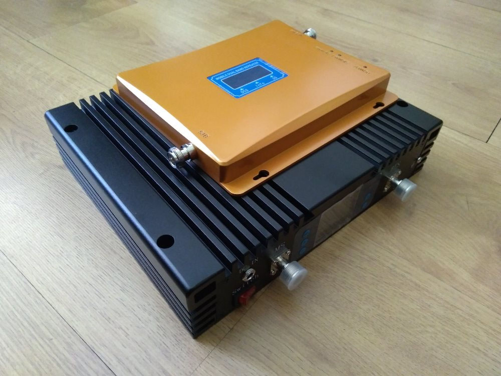
Sample Two - Black Repeater RF-Link 1800 / 2100-75-23
Price: 59 500r.
Contents of delivery:
- Repeater;
- Power Supply;
- Power cord;
- Instruction;
- Fastening for mounting on the wall;
- Packing box.
Specifications:
- Ranges: 1800 \ 2100 MHz;
- Gain:
Downlink: 75 dB;
Uplink: 70dB; - Output power:
Downlink: 23 dBm;
Uplink: 20 dBm; - Wave resistance: 50 Ohm;
- Range of manual adjustment of an attenuator: 32 dB, with a step of 1 dB;
- Range of automatic adjustment of the input signal level: not less than 30 dB;
- Supply voltage:
AC voltage 110-220 volts;
A constant voltage of 10 volts.
Appearance


Indicator and controls

With the rear cover removed

One of two blocks with the cover removed.
We will analyze the amplifier in more detail.
Channel downlink.
Amplifier six-stage.
After the duplex filter, a low-noise amplifier, then the first attenuator of the AGC circuit, amplifying stage, manual attenuator, the second attenuator of the AGC circuit, two amplifying stages, a pre-output amplification stage, an output transistor and a duplex filter.
Uplink channel is built similarly. Output transistor applied lower power.
After each amplification stage, bandpass SAW filters are included.

The output envelope detector of the AGC circuit is turned on after the output transistor through a directional coupler, which eliminates its influence on the output stage.
The AGC circuit of each of the amplification channels is assembled on two operational amplifiers and five transistors.

Each channel feeds its own linear voltage regulator, this is done to further filter the output transistor supply voltage and intermediate amplification stages.

Adders combining band amplifiers placed in a separate shielded unit.

The repeater is controlled by three microcontrollers. One in each amplifier block, the third is located on the indicator board. Data exchange between the blocks and the indicator board takes place via RS-485 protocol.
The microcontroller of the amplifier unit controls the manual gain control attenuators, the output level indicators, the overload indicator, and also sets the reference level for AGC circuits.

Uplink microcontroller and AGC circuit

Indicator board
On the indicator board there are buttons for manual gain control, LCD downlink / uplink output level indicator, overload indicator.
The block of 2100 MHz is made similarly.
Soldering is performed by a soldering robot, in rare places there are traces of manual soldering.
Note: since the printed circuit board is unified and manufactured with the expectation of three 1800 \ 2100 \ 2600 ranges, adjustment \ coordination of the stages for each range is necessary, the main elements are soldered by the robot, matching elements (capacitors, inductors, resistors, etc.) are set manually in the process of configuring the repeater.
Testing
Amplitude-frequency response Downlink 1800

Input level -60dBm.
The maximum gain is 77.2 dB.
The minimum is 73dB.
Uneven frequency response in the working range of 4dB.
Amplitude-frequency response Downlink 2100

Input level -60 dBm
The maximum gain is 74.9 dB. The minimum is 71.6 dB. Uneven frequency response 4.3 dB.
Everything is good here, nothing to add.
Amplitude-frequency response of Uplink 1800

Input level -60dBm.
The maximum gain is 69dB. Minimum 51dB. Irregularity 18dB. The 1780-1785 MHz section is heavily littered.
Amplitude-frequency response of Uplink 2100

Downlink 1800 Maximum Output Power
The signal level at the input -50dB.


Output power (RMS) 22.4dBm. Peak power is 25.7 dBm.
Signal distortion is minimal.
Estimate the overload capacity of the amplifier. Let's do a stress test.
The signal level at the input -10dB .


The output power remained at the same level, the distortions increased, but they are within the normal range. And this is at an input level of -10dBm ! The range of AGC is 38 dB . Automatic adjustment scheme copes with its task.
The overload indicator lights up when the input signal is -42 dB.
Downlink 2100 Maximum Output Power
Input level -50dB.


Distortions.


Input level -10dB.


Distortions.


Maximum output power of Uplink 1800


Distortions.


Input level -10dB.


Distortions.


Maximum output power Uplink 2100
Input level -50dB.


Distortions.


Input level -10dB.


Distortions.


Measurement of intermodulation products
Imitation of the work of two base stations. Frequencies 1820 MHz and 1865 MHz, the signal band 5 MHz.
QPSK modulation.


The signal level at the input of the repeater is -40 dBm and -38 dBm.
Intermodulation products in Uplink 1800 at a frequency of 1730 and 1775 MHz, with a level of -27 dBm and -18 dBm.
There is interference, but they are minimal and insignificant.
Pros:
- Output power and gain are fully consistent with the declared characteristics.
- There is a manual and automatic gain control;
- In the downlink output stage, an output transistor with a high output power (with a large margin) is applied;
- The output envelope detector is turned on via the directional coupler;
- The output level indicator displays information in two forms, it is a segment indicator and a digital indicator. The output level is displayed in dBm;
- The output level indicators display the level very accurately, with a spread of + -1 dBm;
- Information on the indicator is displayed simultaneously for Downlink and Uplink;
- There is an overload indicator;
- Duplex and surfactant filters of good quality;
- Good screening. Downlink and Uplink amplification channels are far apart;
- Installation of band amplifiers in two independent shielded units;
- Totalizers amplifiers made in the form of a separate shielded unit;
- This made it possible to minimize the mutual influence of the amplifiers on each other.
Of the minuses price.
Financial component:
RF-Link 1800 / 2100-75-23 costs about 60 thousand rubles against 10 thousand for the yellow repeater.
Intermediate technical findings
As can be seen from the comparison, the important elements of the repeater are manual gain control, automatic gain control, properly operating overload indicator.
The absence of an AGC circuit in the “yellow” repeater leads to a sharp increase in distortion when the input signal exceeds the nominal level, the absence of an overload indicator and an incorrectly calibrated level indicator do not allow the repeater to be properly configured. The slightest increase in the input signal leads to the appearance of signal distortion in the channel and the appearance of interference. , .
. , \ (\) , . , , . . , , .
Uplink. , . .
, «» . .
, Downlink Uplink. . , , . - .
.
, ( ). , , . – 700 . , 2-3 . 90 . .
, Aliexpress. , - EVM , , 20 5-10 , , , .
MobileBooster.ru.
Source: https://habr.com/ru/post/453830/
All Articles