4-bit BCD counter

BCD means binary coded decimal - binary-decimal, that is, the counter counts from zero not to fifteen, but only to nine, and at the tenth pulse it is again reset to zero. To do this, it provides an additional node.
Actually, the counter, as usual, is a chain of four T-flip-flops:

')
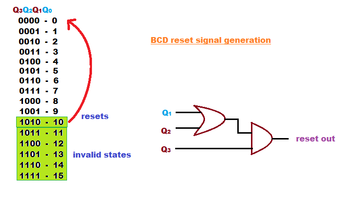
An additional reset node is connected to the three most significant bits of the counter and is triggered at the moment of transition from number 9 to number 10, producing a reset signal, and instead of 10 it turns out immediately 0:
From the structural scheme we proceed to the principal:
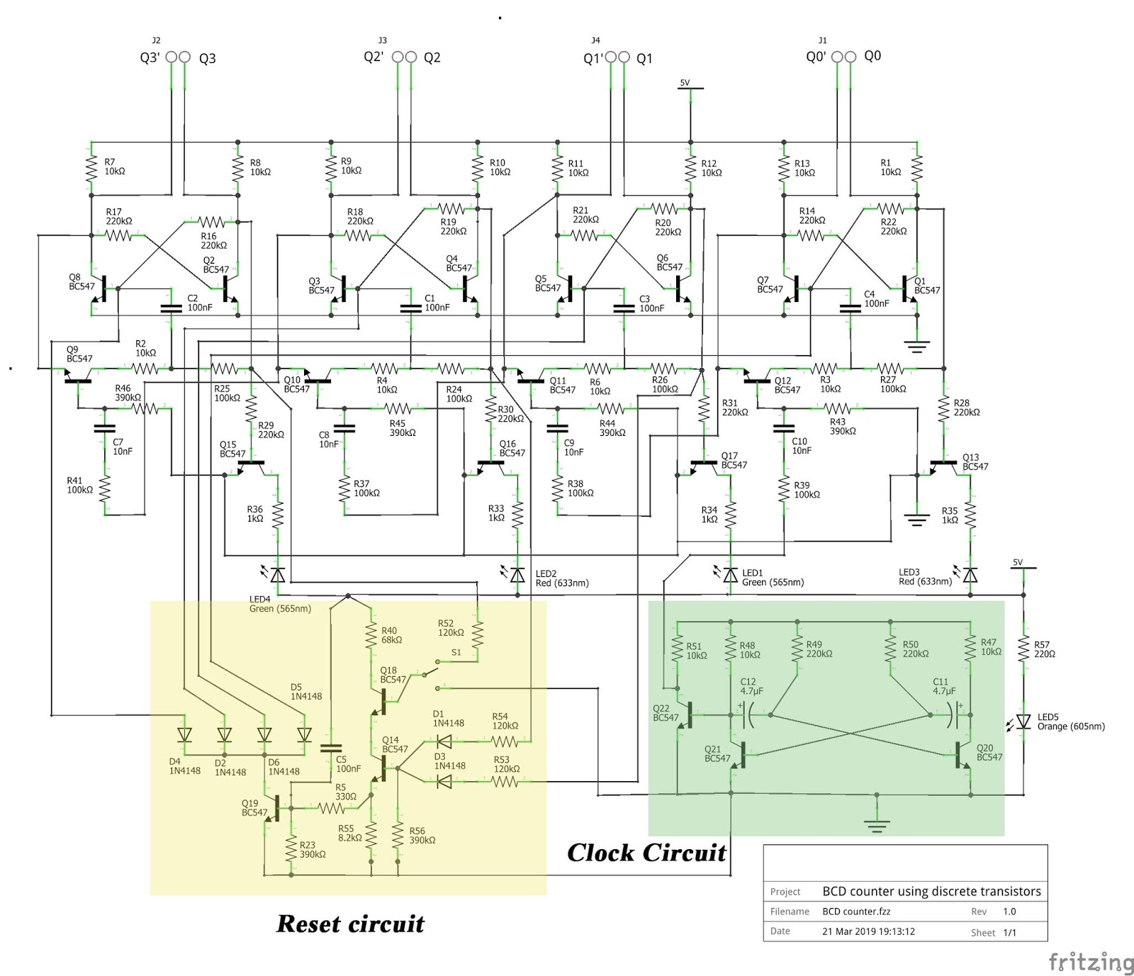
On a fragment of the scheme, not highlighted in any color, four identical T-flip-flops are shown above. Below are the buffer stages, each of which matches the output of the previous trigger with the input of the next. The output of the fourth trigger through the same cascade is connected to the input of the first. The keys for controlling the LEDs are shown just below. If the internal display is not needed, they can be deleted. Direct outputs Q0 - Q3 and inverse Q0 '- Q3' will continue to work as before.
The orange color on the diagram indicates an additional reset node. The switch in the lower position connects one of the three inputs of this node with a common wire, which is why the meter, if necessary, turns into a regular binary one. Forced reset does not occur, the counter moves from the number 15 to the number 0 when overflow. In the upper position of the switch, all the required signals come to the node input, the reset signal is generated as described above, and the counter operates as a binary decimal signal. The node is arranged as follows: on two diodes, an OR element is executed, on two transistors connected in series - element I. Then follows a buffer cascade, from which through four diodes a reset signal is sent to each of the four triggers.
Finally, a green fragment with a clock generator is highlighted. It consists of a symmetric multivibrator and a buffer inverting cascade. The generator is needed only for debugging the circuit, then it must be excluded, and the input of the counter should be connected to the source of pulses that need to be read.
Device video:
Source: https://habr.com/ru/post/453484/
All Articles