Making a reverb pedal using PT2399 microcircuits (part 1)
Introduction
Real reverberation occurs in the working chamber when the generated sound is reflected from walls, furniture, people or any other object in a complex three-dimensional space. The natural reverb process is shown in Figure 1.
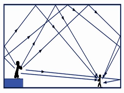
Figure 1. Reverberation in a real situation.
In the good old days, the only way to reproduce the reverb effect is to use a real reverberation chamber — a large room with a complex geometry and carefully selected material for the walls, with speakers and a microphone in certain places inside the chamber. The first attempt to simulate reverberation in a room without a real reverberation chamber was made using a reverberation tank with a spring (see Ref. [1]). The basic design of the spring reverb is shown in Figure 2.
')
Figure 2. Spring Reverb Tank Design
The audio signal excites the input coil, which transmits mechanical vibrations to the nearest end of the spring, and then to its far end, and returns with a decreasing amplitude. Complex waves, both transverse and longitudinal, are generated inside the spring. High-frequency and low-frequency waves move along the spring at different speeds, and spring connections add reflections. To obtain time delays of various types, springs of various types are used: thickness and type of metal, number of turns, diameter of the spring. The artificially reverberated sound created by the spring is then picked up by the output coil and returned to the electronic circuit for mixing with the input audio signal and amplification.
Digital simulation of the reverb effect
The processing of the reverb effect has been extensively studied and, in the opinion of the author, can be classified as follows:
1. Reproduction of the system response: this method views the simulated system as a black box, we do not care what happens inside it, and we simply measure the output response using “convolution processing” (see reference [2]). Regardless of whether the modeled system is a real concert hall or a real reverb reservoir with a spring or a plate, this method will be very simple to implement, but very high computational power will be required for “convolution processing”.
2. Physical modeling: this method analyzes the physical process of the simulated system, models it. This can lead to a very realistic sound, but may require significant computational costs depending on the optimization or mathematical simplification of the model. One example of spring reverb modeling is given by reference [3].
3. Synthetic modeling: sometimes the author sees that such a model is simply a simplified model of approximating the response of a system by trial and error. For example, the Schröder reverb [see Link [4]) can be configured to mimic medium-sized room reverberation by setting certain values for a parameter.
Realization of the reverb effect in the electronic circuit: a network with a delay and tuned analog resonators
When we analyze the reverberation phenomenon as a complex echo pattern, we can intuitively construct such a reverb effect circuit using a network of delay lines. On the other hand, if we analyze the phenomenon of reverberation as a continuous resonance, we might think that several parallel analog resonators tuned to different frequencies can be used to create such an effect. The author has been thinking about this for many years. Please let the author know in the comments if you already have an analog reverb circuit that is based on analog resonators so that the author does not reinvent the wheel. At the moment, the author has focused on the solution with a chain of delay lines.
PT2399 Digital Delay Chip - Low Cost Solution for DIY Reverb Pedal Project
The advanced CMOS PT2399 technology from Princeton is becoming increasingly popular for designing a device with a switchable capacitor bank (BBD) for storing audio samples in “analog” as an implementation of an analog delay line. A block diagram of PT2399 is shown in Figure 3.

Figure 3. Block diagram of a PT2399 digital delay line IC
The digital chip of the delay line is made in an accessible 16-pin DIP package. The minimum delay time is 30 ms, the maximum is 340 ms, and the delay setting is easy to change with an external resistor.
Block diagram of a Hamuro Spring-Room-Hall reverb for a small room

Figure 4. Block diagram of the Hamuro Spring-Room-Hall reverb
The author has created a very simple reverb scheme using 5 PT2399 microcircuits, which can simulate the effect of spring reverberation in a room. It has the ability to control the delay time, volume of the room and balance. When the room volume control is set to minimum, it will sound like a spring reverb, and if it is set to maximum, a reverb will be obtained like in a hall or cathedral.
Schematic diagram of the full contour
A complete schematic is under development and testing. The basic reverb scheme was successfully tested on the Deepstomp (DIY digital multi-effect stompbox) platform, and will be published in the second part of the article (author's note).
Literature
1. L. Hammond, "Electical Musical Instrument", US Patent 2,230,836, February 2, 1941
2. Fons Adriensen, “Measuring Acoustic Pulse Response with ALIKI”, 4th International Linux Audio Conference: LAC2006
3. Stephan Bilbao and Julian Parker, “The Virtual Model of Spring Reverberation,” IEEE Transaction on Sound, Speech, and Language, Vol. 18, No. 4, May 2010, p. 799
4. M. R. Schröder (Bell Telephone Laboratories, Incorporated, Murray Hill, NJ)
Natural Sounding of Artificial Reverb, Audio Engineering Society Journal, July 1962
Source: https://habr.com/ru/post/453258/
All Articles