Running lights on the relay
If you have previously assembled running lights on transistors, thyristors or microchips, you may be interested in realizing the same effect on the relay.
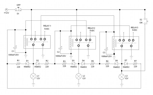
Each of the three relays in this circuit is supplemented with an RC-circuit providing a delay, as well as a diode “OR” for control from two places. One of the inputs of each diode "OR" is connected to the load of the previous relay, the other to the load of its own. Thus, having received a delayed response signal from the previous relay and triggered, the relay self-locks, which is equivalent to the S-RS flip-flop input.
')
Each of these "triggers" has an input / R - the top output of the winding. Relay release occurs when this pin is connected to the common wire. Short circuit does not happen, because the current is limited by the resistors of the RC-chains. In the world of ladder logic, there are also pull-up resistors. If the signal S for each "trigger" comes from the previous relay, then the signal / R - from the next.
Immediately after switching on, the circuit does not work, since there is no logical unit at the inputs S of all three “triggers”. To start running lights, use the S2 button, to stop - the S1 button.
Resistors RC-chains are selected by the formula:
U relay / U pit = R obm / (R obm + R ogre ), where:
U relay - rated voltage of the relay coil, V
U pete - supply voltage, V
R obm - winding resistance, Ohm
R ogre - resistance of the resistor RC-chain (required), Ohm
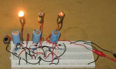
The power of the resistor is selected with a certain margin, based on the fact that it is pull-up, and when applying the / R signal, the full supply voltage minus the voltage drop across the diode is applied to it. To set the switching speed, you can pick up RC capacitors. Device in action:
Source: https://habr.com/ru/post/453238/
All Articles