As I did not prepare and held a rosanov seminar on FPGAs in Moscow. Plans to do the same in Las Vegas and Zelenograd
You have such a dream: you end up on an exam or speak in front of a certain audience, and suddenly you realize that you didn’t prepare at all and now you have to improvise. It was in this situation, but not in a dream, but in real life, I faced the May holidays in Moscow, where I flew from California to hold a three-day seminar for carefully selected schoolchildren from leading Moscow physics schools. Under the auspices of RUSNANO, in the gymnasium of RTH (MIIT) and in the presence of teachers from MIET, MIREA, MEPI, MEI and HSE MIEM.
The Moscow colleagues hoped for me, and theoretically I would have had to bring along step-by-step instructions and examples of various exercises on the board with a chip of reconfigurable logic. In reality, I had a bunch of some examples for other cards, of which I did not build anything in the confusion of flights and other events.
Therefore, I took a kind of universal example, which I wrote a year and a half ago, sitting in an Alma-Ata-Astana plane, threw out all the insides from the example and started filling it with schoolchildren, without a hard plan. And oddly enough - it turned out. In the process of filling, instructive moments of digital circuitry and Verilog hardware description language have arisen, which would not arise when planning.
')
On June 4, I and colleagues at Wave Computing conduct a similar seminar in Las Vegas, but only for adults, and on July 8-19, I help MIET to conduct a summer school in Zelenograd. Plans for these events (not final, but for discussion in the group of teachers and engineers, including here on Habré) - at the end of the post.

Why do we need a FPGA workshop for schoolchildren? Programmable logic integrated circuits (FPGAs or FPGAs - Field Programmable Gate Arrays) are a traditional way to consolidate knowledge by practice when studying the design of digital circuits at the level of register transmissions, using hardware description languages. In other words, the key technology for developing iPhones - the chips inside iPhones are designed that way. The backlog of Russia on iPhones was also due to the fact that the Labs on FPGAs, micro-architecture and languages descriptions of the equipment were introduced in Berkeley and MIT in the early 1990s, and in Russia because of the collapse of the USSR - much later.
The last Rosnan seminar went surprisingly smoothly, primarily because the students who attended it had previously completed a theoretical online course with a career guidance overview of modern chip design methods. The online course is designed for advanced students of the Olympiad type and consists of three modules: "From the transistor to the chip" , "The logical side of digital circuitry" and "The physical side of digital circuitry . " In this course, students learn about the so-called RTL2GDSII route - a group of technologies that are used by engineers in electronic companies to design mass chips, Application Specific Integrated Circuits - ASIC. FPGAs / FPGAs are used for prototyping ASICs, including companies such as Intel, Apple, and NVidia.
As the students went through the online course, they had already learned what a D-trigger, a finite state machine, logical synthesis and tracing are. The language of the description of the equipment, they also saw in the online course. Now this knowledge, which lay in a passive form in their memory, needed only to be revived.
Now I will always be for any seminars in the CIS countries (besides the seminars already planned, I have suggestions to hold it in Minsk, Sochi and Yakutsk) to set the condition that the receiving party first skips schoolchildren or students through the three modules of the online course, since after he remains only motivated people who have already gone through all the tedious aspects, and for reinforcement there is pure creativity, the last moment, like the fall of an apple that hit Newton on the head. In addition, the online course links all this activity to adult occupations, the next stage, draws a distant goal.
So, before the flight to Moscow, I launched a universal example at my home in Sunnyvale, California. Sample code :
On the first day of the workshop, we practiced with small-scale integrated circuits on the breadboard. This technology is 50 years old, but no one has invented better, as is evident, in real life, and not in simulation, to show the work, for example, of D-triggers. Although it seems to many modern teachers of technology in schools that it is outdated and unnecessary, but in the course of 6.111 of the Massachusetts Institute of Technology now, in the 2018/2019 academic year, the first lab on digital circuitry goes exactly like this with small-degree integrated circuits - see http: //web.mit.edu/6.111/volume2/www/f2018/index.html .
In addition, using the example of connecting microcircuits of a small degree of integration with buttons, it is convenient to explain what it is, what is needed and how pull-up resistors work. And why do they give potential 0 when the button is not pressed, and how it is connected with the voltage divider.
Even when using an example with a microcircuit of a small degree of integration, the LED burns out, then schoolchildren get life experience, that putting a resistor there is a must. If they see it on the computer screen in the software simulator of the breadboard, they will not get such a life experience, because you can draw anything on the screen and the students will not be sure that burnout is true.
Here's how the function of the D-flip-flop is visible on the chips of a small degree of integration:
The second day began with a historical excursion: how the chips were designed 50 years ago and how it has been revolutionized twice since then. One of the revolutions superimposed on the collapse of the USSR and this is the main technical reason why Russia does not have its own iPhones.
At 8.45, the story of how a Soviet bui-spy was caught in the world ocean, which followed the movement of the American ships, and what it led to.
On March 13, the story of how one post by blogger John Cooley shifted the entire global industry from VHDL to Verilog.
At 16.10, the story of how Microsoft Windows lost to Linux as a platform for the work of chip designers.
In this part - a demonstration of how to run a program for the synthesis of digital logic and firmware configuration in FPGA. In two ways - by running the script under Linux and in an integrated graphical shell. Also a brief description of the content of the demo. After this gallop across Europe, schoolchildren sit down behind a graphical shell and do simple exercises, starting with AND-OR-NOT logical elements, whose inputs are connected to buttons, and the outputs to LEDs. Approximately like this:
Along the way, two interesting questions arose at once. Firstly, at first I forgot myself that on this board both the buttons and the LEDs are inverted. I mean, when the button is pressed, it is on wire 0, and when it is not pressed, it is 1. And when the LED sends 0, it is on, and when 1 is off. If you don’t know about inversion, the AND gate (led [0] = key [0] & key [1]) starts to behave like OR, and OR like I. Laws of Morgan in action! ~ (a & b) == ~ a | ~ b, and also ~ (a | b) == ~ a & ~ b.
But even after the amendment, for some schoolchildren, this case still worked the other way. Then I looked at their code and found that when they were rewriting the code that I wrote on the board, they thought that “~” (tilde) is “-” (minus). This gave me an excellent reason to tell about the difference between direct and additional code, as well as why for single-bit numbers (- 0) == 0 and (- 1) == 1, while (~ 0) == 1 and (~ 1) == 0. And also to calculate its negation for multi-bit numbers in the additional code, it is enough to invert it bit-by-bit and add one: - a == ((~ a) + 1).
Continuation - parts 2.3 , 2.4 , 2.5 .
The entire session took place under Linux, more precisely under Lubuntu 18.04 with Intel FPGA Quartus II installed on it. Lubuntu was loaded with SSDs on which Intel FPGA Quartus II Lite Edition 18.1 was also installed. To boot from the SSD, you just need to plug it into the USB 3.0 port, turn on the computer and press F12. Then enter the menu and say "ship from USB".
Although the software for synthesis for FPGA is also available for Windows, but Linux is good for two reasons:
1. Linux is able to work on weaker computers than Windows. For example, I have a laptop with 2 gigabytes of memory, so Intel FPGA / Altera Quartus II under Windows rests on it, and under Linux it works fine.
2. All adult developers of mass chips in Apple, NVidia and other electronic companies use Linux, which runs Synopsys Design Compiler, Synopsys IC Compiler, Synopsys VCS, Cadence IES, etc.

Why it is better to do everything on bootable SSD, and not to put on computers in the classroom? Because installing software from FPGA companies is a rather tedious process, and around Altera Quartus or Xilinx Vivado you need to run with a tambourine, change files in / etc and install old 32-bit libraries for some components, in particular for the free version of Mentor ModelSim. Some libraries generally have to be collected from source. There are scripts from Stanislav Zhelio , which do it all automatically, but even with this script, installing everything on the computer will take a couple of hours.
Why not do everything in virtual machines? For example with VirtualBox? We tried it in Moscow State University and other places, but there may be glitches with USB pulling. A bootable SSD with Lubuntu looks like the best option.
To prepare a set of SSDs for a seminar, you need to put everything on one SSD, and then clone it with a command that allows you to immediately write to three SSDs from one:
Here you need to know that not all SSD enclosures support Linux, for example, Kingwin Data Star spoils disks. Correct enclosures - Orico and Eluteng.
Also, I do not recommend trying to replace SSD with simple bootable USB flash drives. Although it also works on USB flash drives, some operations are incredibly slow, causing discomfort and irritation. But on bootable SSD drives with USB 3.0 everything flies faster than Linux on the internal hard drive.
I also tried sticking a bootable SSD drive on an Apple Mac by pressing the Option key while booting, but it didn’t work. Neither via USB 3.1 port, nor through 3.0. It seems that the Mac does not want to understand when Ext4 file system, or partition table when loading. Are there makovods and linuksoids among my readers? It would be interesting to know what to do (besides the option of using VirtualBox or other virtual machines).
Interestingly, only 2 students from the entire group used Linux before the seminar. For me, this is very strange, since on the place of the Russian Minobra I would transplant all Russian schools to Linux 10 years ago, when Ubuntu became user-friendly. In addition to Ubuntu, it would be possible to make a special Russian version of Linux for education. Vindous clogged with viruses, you need to pay royalties for it, what Windows is better than Linux for let's say school programming courses on Python? Or the schoolchildren won't have enough Google docs, but it is Microsoft Word that is needed? I just do not understand.
Even the South Korean government decided in 2020 to switch to Linux .
In any case, the schoolchildren did not have any problems with Linux at my seminar, although, as I said, the majority of schoolchildren used it for the first time.
I was late for the beginning of the third day because I was invited to give a lecture to the Russian branch of Samsung and the event was delayed for 3 hours (you can download lecture slides: 1 , 2 , 3 and an article about some of the content ), after which I got hungry and only during eating buckwheat and Olivier in Mumu (I miss this in California) found that my class at the gymnasium would begin in 5 minutes.
Then I called Alexander Silantyev from MIET and asked me to start the lesson without me. On the previous day, schoolchildren began to practice with a seven-segment indicator, displaying one letter. Now, if we cross the output of a single letter with the shift register, we can realize the output to a multi-digit seven-segment dynamic indicator, and at the same time schoolchildren will learn how to encode sequential logic on the verification.
The plan was a success - when I entered the class, some students were already slowly running letters on the dynamic indicator, and so that they merged into words, it was enough just to raise the enable signal generation frequency for the shift register:
Then I handed over the word to Stanislav Gelnio sparf from IVA Technologies, and he briefly outlined how to move from simple logic blocks to a tiny, but completely real processor (see Stanislav’s posts on Habré and schoolMIPS on GitHub ):
The continuation of the lecture by Stanislav Zelio
The seminar was held at the Grammar School of the Russian University of Transport (MIIT). Irina Grunicheva and Gleb Romanov (eNano) helped at the workshop and before it; Alexey Pereverzev, Alexander Silantyev and Evgeny Primakov from MIET, Alexander Romanov from HSE MIEM and his students, Alexey Kochnov from NIISI, League of Robots (obraz.pro), Pavel Kirichenko (ICST, Intel, author of books bhv.ru/books/book. php? id = 201192 ), Yegor Kuzmin from IPPM RAS, Daria Krivoruchko, a schoolgirl from SSC, was in LSYUP, Timofey Cherkasov (Academy of Digital Technologies of St. Petersburg, School of Engineering Thinking LNMO), Alexander Bakerenkov and Yulia Shaltaeva from Pre-University MIFI, Vladimir Vorontsov from MEI, Evgeny Pevtsov from MIREA, Vitaly Kravchenko from Nautekh, Arkady Po Yakov and Sergey Pevchenko of MEI.
Ruslan Tikhonov from Ampere brought components for exercises with microcircuits of a small degree of integration.
The publisher Dmitry Movchan, from MQK Press, presented each participant with useful books - David Harris and Sara Harris, a thick comprehensive textbook, Digital circuit design and computer architecture, and light reading from A. Hideharu, Entertaining electronics. Digital circuits. Manga
Maksim Maslov, associated with MIPT, came to the seminar and donated FPGA boards to summer schools (and they used to say that in Russia there is not enough charity for the needs of education).

What will be next? And then there will be two events that will expand and deepen what we did at the Grammar School of RTH. July 8-26 will be the summer school MIET in Zelenograd. Here is a proposal for her program. Her first two weeks consists of five parts:
But even before school on June 4 there will be a seminar in Las Vegas, where we will deal not with the school processor, but with the industrial one.

More detailed program in Zelenograd:
Week 1. Basics of digital logic.
Day 1. Chips of a small degree of integration, exercises with combinatorial logic
Day 2. Chips of a small degree of integration, exercises with sequential logic
Day 3. FPGA, exercises with buttons, switches, LED, seven-segment indicator
Day 4. FPGA, output of geometric shapes on VGA
Day 5. FPGA, state machine for Angry Birds
Week 2. Processor
Day 1. Programming in assembly language.
Day 2. One-cycle processor schoolMIPS.
Day 3. Integration of the processor with the output of geometric shapes on the VGA.
Day 4. Lecture about interruptions and multitasking. Individual project - a video game programmable on a video processor with output to VGA.
Day 5. Lecture about the conveyor. Competition of individual projects.
Week 1. Day 1. Chips of a small degree of integration.
1.1. Exercises with combinatorial logic.
1.1.1. The XOR logic element on the CD4070, without buttons and pull-down registers - repeat the demonstration.
1.1.2. Logic element XOR, add buttons and pull-down registers - repeat the demonstration.
1.1.3. Individual task - on datashit to build a demonstration of one of the logical elements AND / OR / NOT / XOR / NOR / NAND / XNOR, with two, three, four or eight inputs:
1.1.3.1. CD4081, Quad 2-Input AND
1.1.3.2. CD4071, Quad 2-Input OR
1.1.3.3. CD4011, Quad 2-Input NAND
1.1.3.4. CD4001, Quad 2-Input NOR
1.1.3.5. CD4073, Triple 3-Input AND
1.1.3.6. CD4025, Triple 3-Input NOR
1.1.3.7. CD4082, Dual 4-Input AND
1.1.3.8. CD4072, Dual 4-Input OR
1.1.3.9. CD4012, Dual 4-Input NAND
1.1.3.10. CD4002, 4-Input NOR
1.1.3.11. CD4068, 8-input AND NAND
1.1.3.12. CD4078, 8-Input NOR
1.2. 7-segment indicator with a common cathode.
1.2.1. Assemble on a breadboard with resistors, try individual segments.
1.2.2. Combination with 7-segment indicator driver, CD4511, BCD to 7-Segment Latch Decoder.
1.2.3. Option - an indicator with a common anode. Combine with inverter CD4069, Inverter.
1.2.4. Option - add 4 buttons with pull-up resistors on the input of the CD4511.
1.3. Combined logic blocks - individual assignment at the end of the day or as homework:
1.3.1. CD4532, 8-Bit Priority Encoder
1.3.2. CD4051, Single 8-Channel Analog Switch, used as digital decoder
1.3.3. CD4051, Single 8-Channel Analog Switch, used as digital multiplexer
1.3.4. CD4052, Dual 4-Channel Analog Switch, used as digital multiplexer
1.3.5. CD4053, Triple 2-Channel Analog Switch, used as digital multiplexer
1.3.6. CD4008, 4-Bit Combinational Adder
1.3.7. CD4063, 4-Bit Digital Comparator
1.3.8. CD4585, 4-Bit Digital Comparator
At the end of the day, everyone shows who did what.
Week 1. Day 2. Exercises with sequential logic.
1.2.1. Assemble a clock signal generator based on a 555 chip. Try different capacitors and resistances.
1.2.2. D-flip-flop on the CD4013 chip, Dual D-Flip-Flop With Set-Reset.
1.2.3. Individual project:
1.2.3.1. Shift register based on CD4015, Dual 4 Bit Static Shift Register, serial-in, parallel-out.
1.2.3.2. Shift register based on CD4035, 4-Stage Shift Register, parallel-in, parallel-out.
1.2.3.3. Shift register based on CD4014, 8-Stage Shift Register, parallel-in, serial-out.
1.2.3.4. Counter with LED output CD4029, Binary Decimal Up Down Counter.
1.2.3.5. The counter with a conclusion to the 7-segment indicator through the driver.
1.2.3.6. More complicated is a combination of CD4035 shift registers (parallel-in, serial-out) with serial adder CD4038. To him you need an inverter CD4069. Before that I will demonstrate serial adder CD4032 without inverter.
1.2.3.7. A more complicated one is a combination of CD4014 shift registers (parallel-in, serial-out) with serial adder CD4038. To him you need an inverter CD4069.

Week 1. Day 3. FPGA, exercises with buttons, switches, LED, seven-segment indicator
1.3.1. Logic element on combinational logic - input from buttons, output to LEDs.
1.3.2. Output one letter on the seven-segment indicator.
1.3.3. The simplest multiplexer is the output of a letter depending on the key pressed. Implementation with the help of constructions "?", "If", "case".
1.3.4. Shift register.
1.3.5. Output a word to an eight-digit dynamic seven-segment indicator using a shift register.
1.3.6. Individual project, perhaps homework for the weekend:
1.3.6.1. Figures on the LED matrix.
1.3.6.2. Snake running on a seven-segment display.
1.3.6.3. Sound signal generation, sound organ.
1.3.6.4. Enter from the 16-button keyboard.
1.3.6.5. Code lock - recognition of the key sequence by the state machine.
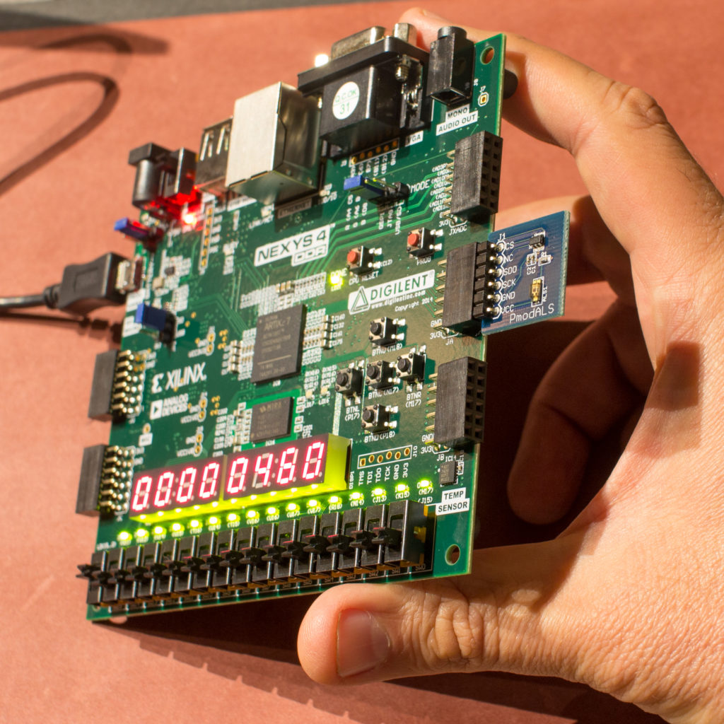
1.3.6.6. Integration with a sensor - rangefinder.
1.3.6.7. Integration with corner encoder.
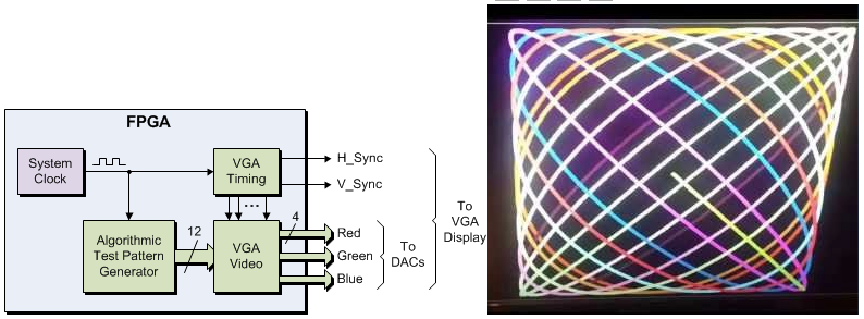
Day 4. FPGA, output of geometric shapes on VGA
Day 5. FPGA, state machine for Angry Birds
Week 2. Processor
Day 1. Programming in assembly language.
Day 2. One-cycle processor schoolMIPS.
Day 3. Integration of the processor with the output of geometric shapes on the VGA.
Day 4. Lecture about interruptions and multitasking. Individual project - a video game programmable on a video processor with output to VGA.
Day 5. Lecture about the conveyor. Competition of individual projects.
About the rest of the school days more details will be in a separate post, after discussing this in the summer school organizing committee. If you want to participate in the summer school at MIET in Zelenograd as a student or instructor, the organizers have just laid out contacts and registration . If you are a schoolchild, then it’s important that you complete all three modules of the Rosnan online course before July ( “From Transistor to Chip” , “Logical Side of Digital Circuit Engineering” and “Physical Side of Digital Circuit Engineering” ). The practice will be hard, and we are not able to stop to figure out which cycle contains which value is at the input or output of the D-flip-flop. It doesn’t fit right into your head, but if you take an online course, it will be easier for you.

A few details about the workshop in Las Vegas on June 4 :
It is not often the case that an engineering workshop, originally developed for Russia, and tested in Russia (including the MIPT), Ukraine and Kazakhstan, then begins in Las Vegas at the electronics design automation conference. In Russia and Ukraine, it was called the “MIPSfpga Workshop”, and at the Design Automation Conference it is called the “MIPS Open Developer Day”. Come June 4 at the Embassy Suites by Hilton Convention Center at 3600 Paradise Road, Las Vegas, and you will take part in a show that students and teachers of Moscow State University, MIPT, MEPI, Zelenograd MIET, St. Petersburg ITMO, Tomsk TSU, Kiev KPI, Almaty AlmaU and partly of Nazarbayevsky University in Astana.
MIPSfpga is a package that contains the processor core in the source code on Verilog, which can be changed, add new instructions, observe the work of the cache and pipeline, build multiprocessor systems, change software and hardware, etc. at the same time. In the new version of the seminar, you will add a coprocessor to the processor to speed up the algorithms of artificial intelligence.
In addition, in the new version of the seminar we will show how to configure the kernel from the MIPS microAptiv UP package and insert it into the MIPSfpga harness. When configured, you can create exotic processor variants, for example, a processor with 16 sets of 32 registers. You can automatically switch these sets when entering an interrupt and thereby quickly change the context without saving / restoring the context from memory, which in the usual RTOS takes about a thousand cycles.
MIPSfpga is not intended to be introduced into an item from absolute zero. For its fruitful use, it is necessary that the student already knows the basics of digital circuitry, knows how to program in C and assembler, and also present the concepts of microarchitecture - pipeline, pipeline conflicts, etc. This is what is studied in schoolMIPS, which we use in Zelenograd.
Here is a slide about the mechanism for adding instructions to the MIPS microAptiv UP processor:
At a seminar in Las Vegas on June 4 and probably at the summer school of young electronics engineers, which will be held July 8-26, at MIET in Zelenograd, my daughter Elizabeth Panchul will help me (if she receives a visa in time). Since Elizabeth is semi-sub-semi-Russian / Ukrainian, she speaks only English. Therefore, Russian instructors (students or graduate students of the Moscow Institute of Physics and Technology, Moscow State University, etc., who are ready to help us with Elizabeth and MIET students in conducting the school) can learn the correct English accent, and she from them - the basics of Russian. In addition to learning Verilog, MIPS, architecture, micro-architecture, and organizing DMA into memory when displayed on a graphical screen:

We are waiting for you at all seminars, as well as in committees for creating their programs!
The Moscow colleagues hoped for me, and theoretically I would have had to bring along step-by-step instructions and examples of various exercises on the board with a chip of reconfigurable logic. In reality, I had a bunch of some examples for other cards, of which I did not build anything in the confusion of flights and other events.
Therefore, I took a kind of universal example, which I wrote a year and a half ago, sitting in an Alma-Ata-Astana plane, threw out all the insides from the example and started filling it with schoolchildren, without a hard plan. And oddly enough - it turned out. In the process of filling, instructive moments of digital circuitry and Verilog hardware description language have arisen, which would not arise when planning.
')
On June 4, I and colleagues at Wave Computing conduct a similar seminar in Las Vegas, but only for adults, and on July 8-19, I help MIET to conduct a summer school in Zelenograd. Plans for these events (not final, but for discussion in the group of teachers and engineers, including here on Habré) - at the end of the post.
Why do we need a FPGA workshop for schoolchildren? Programmable logic integrated circuits (FPGAs or FPGAs - Field Programmable Gate Arrays) are a traditional way to consolidate knowledge by practice when studying the design of digital circuits at the level of register transmissions, using hardware description languages. In other words, the key technology for developing iPhones - the chips inside iPhones are designed that way. The backlog of Russia on iPhones was also due to the fact that the Labs on FPGAs, micro-architecture and languages descriptions of the equipment were introduced in Berkeley and MIT in the early 1990s, and in Russia because of the collapse of the USSR - much later.
The last Rosnan seminar went surprisingly smoothly, primarily because the students who attended it had previously completed a theoretical online course with a career guidance overview of modern chip design methods. The online course is designed for advanced students of the Olympiad type and consists of three modules: "From the transistor to the chip" , "The logical side of digital circuitry" and "The physical side of digital circuitry . " In this course, students learn about the so-called RTL2GDSII route - a group of technologies that are used by engineers in electronic companies to design mass chips, Application Specific Integrated Circuits - ASIC. FPGAs / FPGAs are used for prototyping ASICs, including companies such as Intel, Apple, and NVidia.
As the students went through the online course, they had already learned what a D-trigger, a finite state machine, logical synthesis and tracing are. The language of the description of the equipment, they also saw in the online course. Now this knowledge, which lay in a passive form in their memory, needed only to be revived.
Now I will always be for any seminars in the CIS countries (besides the seminars already planned, I have suggestions to hold it in Minsk, Sochi and Yakutsk) to set the condition that the receiving party first skips schoolchildren or students through the three modules of the online course, since after he remains only motivated people who have already gone through all the tedious aspects, and for reinforcement there is pure creativity, the last moment, like the fall of an apple that hit Newton on the head. In addition, the online course links all this activity to adult occupations, the next stage, draws a distant goal.
So, before the flight to Moscow, I launched a universal example at my home in Sunnyvale, California. Sample code :
On the first day of the workshop, we practiced with small-scale integrated circuits on the breadboard. This technology is 50 years old, but no one has invented better, as is evident, in real life, and not in simulation, to show the work, for example, of D-triggers. Although it seems to many modern teachers of technology in schools that it is outdated and unnecessary, but in the course of 6.111 of the Massachusetts Institute of Technology now, in the 2018/2019 academic year, the first lab on digital circuitry goes exactly like this with small-degree integrated circuits - see http: //web.mit.edu/6.111/volume2/www/f2018/index.html .
In addition, using the example of connecting microcircuits of a small degree of integration with buttons, it is convenient to explain what it is, what is needed and how pull-up resistors work. And why do they give potential 0 when the button is not pressed, and how it is connected with the voltage divider.
Even when using an example with a microcircuit of a small degree of integration, the LED burns out, then schoolchildren get life experience, that putting a resistor there is a must. If they see it on the computer screen in the software simulator of the breadboard, they will not get such a life experience, because you can draw anything on the screen and the students will not be sure that burnout is true.
Here's how the function of the D-flip-flop is visible on the chips of a small degree of integration:
The second day began with a historical excursion: how the chips were designed 50 years ago and how it has been revolutionized twice since then. One of the revolutions superimposed on the collapse of the USSR and this is the main technical reason why Russia does not have its own iPhones.
At 8.45, the story of how a Soviet bui-spy was caught in the world ocean, which followed the movement of the American ships, and what it led to.
On March 13, the story of how one post by blogger John Cooley shifted the entire global industry from VHDL to Verilog.
At 16.10, the story of how Microsoft Windows lost to Linux as a platform for the work of chip designers.
In this part - a demonstration of how to run a program for the synthesis of digital logic and firmware configuration in FPGA. In two ways - by running the script under Linux and in an integrated graphical shell. Also a brief description of the content of the demo. After this gallop across Europe, schoolchildren sit down behind a graphical shell and do simple exercises, starting with AND-OR-NOT logical elements, whose inputs are connected to buttons, and the outputs to LEDs. Approximately like this:
module top (input [2:0] key, output [7:0] led); wire a = ~ key [0]; // 0, , wire b = ~ key [1]; wire c = a & b; assign led [0] = ~ c; // , 0 endmodule Along the way, two interesting questions arose at once. Firstly, at first I forgot myself that on this board both the buttons and the LEDs are inverted. I mean, when the button is pressed, it is on wire 0, and when it is not pressed, it is 1. And when the LED sends 0, it is on, and when 1 is off. If you don’t know about inversion, the AND gate (led [0] = key [0] & key [1]) starts to behave like OR, and OR like I. Laws of Morgan in action! ~ (a & b) == ~ a | ~ b, and also ~ (a | b) == ~ a & ~ b.
But even after the amendment, for some schoolchildren, this case still worked the other way. Then I looked at their code and found that when they were rewriting the code that I wrote on the board, they thought that “~” (tilde) is “-” (minus). This gave me an excellent reason to tell about the difference between direct and additional code, as well as why for single-bit numbers (- 0) == 0 and (- 1) == 1, while (~ 0) == 1 and (~ 1) == 0. And also to calculate its negation for multi-bit numbers in the additional code, it is enough to invert it bit-by-bit and add one: - a == ((~ a) + 1).
Continuation - parts 2.3 , 2.4 , 2.5 .
The entire session took place under Linux, more precisely under Lubuntu 18.04 with Intel FPGA Quartus II installed on it. Lubuntu was loaded with SSDs on which Intel FPGA Quartus II Lite Edition 18.1 was also installed. To boot from the SSD, you just need to plug it into the USB 3.0 port, turn on the computer and press F12. Then enter the menu and say "ship from USB".
Although the software for synthesis for FPGA is also available for Windows, but Linux is good for two reasons:
1. Linux is able to work on weaker computers than Windows. For example, I have a laptop with 2 gigabytes of memory, so Intel FPGA / Altera Quartus II under Windows rests on it, and under Linux it works fine.
2. All adult developers of mass chips in Apple, NVidia and other electronic companies use Linux, which runs Synopsys Design Compiler, Synopsys IC Compiler, Synopsys VCS, Cadence IES, etc.
Why it is better to do everything on bootable SSD, and not to put on computers in the classroom? Because installing software from FPGA companies is a rather tedious process, and around Altera Quartus or Xilinx Vivado you need to run with a tambourine, change files in / etc and install old 32-bit libraries for some components, in particular for the free version of Mentor ModelSim. Some libraries generally have to be collected from source. There are scripts from Stanislav Zhelio , which do it all automatically, but even with this script, installing everything on the computer will take a couple of hours.
Why not do everything in virtual machines? For example with VirtualBox? We tried it in Moscow State University and other places, but there may be glitches with USB pulling. A bootable SSD with Lubuntu looks like the best option.
To prepare a set of SSDs for a seminar, you need to put everything on one SSD, and then clone it with a command that allows you to immediately write to three SSDs from one:
time sudo dcfldd if=/dev/sdb bs=1M of=/dev/sdc of=/dev/sdd of=/dev/sde Here you need to know that not all SSD enclosures support Linux, for example, Kingwin Data Star spoils disks. Correct enclosures - Orico and Eluteng.
Also, I do not recommend trying to replace SSD with simple bootable USB flash drives. Although it also works on USB flash drives, some operations are incredibly slow, causing discomfort and irritation. But on bootable SSD drives with USB 3.0 everything flies faster than Linux on the internal hard drive.
I also tried sticking a bootable SSD drive on an Apple Mac by pressing the Option key while booting, but it didn’t work. Neither via USB 3.1 port, nor through 3.0. It seems that the Mac does not want to understand when Ext4 file system, or partition table when loading. Are there makovods and linuksoids among my readers? It would be interesting to know what to do (besides the option of using VirtualBox or other virtual machines).
Interestingly, only 2 students from the entire group used Linux before the seminar. For me, this is very strange, since on the place of the Russian Minobra I would transplant all Russian schools to Linux 10 years ago, when Ubuntu became user-friendly. In addition to Ubuntu, it would be possible to make a special Russian version of Linux for education. Vindous clogged with viruses, you need to pay royalties for it, what Windows is better than Linux for let's say school programming courses on Python? Or the schoolchildren won't have enough Google docs, but it is Microsoft Word that is needed? I just do not understand.
Even the South Korean government decided in 2020 to switch to Linux .
In any case, the schoolchildren did not have any problems with Linux at my seminar, although, as I said, the majority of schoolchildren used it for the first time.
I was late for the beginning of the third day because I was invited to give a lecture to the Russian branch of Samsung and the event was delayed for 3 hours (you can download lecture slides: 1 , 2 , 3 and an article about some of the content ), after which I got hungry and only during eating buckwheat and Olivier in Mumu (I miss this in California) found that my class at the gymnasium would begin in 5 minutes.
Then I called Alexander Silantyev from MIET and asked me to start the lesson without me. On the previous day, schoolchildren began to practice with a seven-segment indicator, displaying one letter. Now, if we cross the output of a single letter with the shift register, we can realize the output to a multi-digit seven-segment dynamic indicator, and at the same time schoolchildren will learn how to encode sequential logic on the verification.
The plan was a success - when I entered the class, some students were already slowly running letters on the dynamic indicator, and so that they merged into words, it was enough just to raise the enable signal generation frequency for the shift register:
Then I handed over the word to Stanislav Gelnio sparf from IVA Technologies, and he briefly outlined how to move from simple logic blocks to a tiny, but completely real processor (see Stanislav’s posts on Habré and schoolMIPS on GitHub ):
The continuation of the lecture by Stanislav Zelio
The seminar was held at the Grammar School of the Russian University of Transport (MIIT). Irina Grunicheva and Gleb Romanov (eNano) helped at the workshop and before it; Alexey Pereverzev, Alexander Silantyev and Evgeny Primakov from MIET, Alexander Romanov from HSE MIEM and his students, Alexey Kochnov from NIISI, League of Robots (obraz.pro), Pavel Kirichenko (ICST, Intel, author of books bhv.ru/books/book. php? id = 201192 ), Yegor Kuzmin from IPPM RAS, Daria Krivoruchko, a schoolgirl from SSC, was in LSYUP, Timofey Cherkasov (Academy of Digital Technologies of St. Petersburg, School of Engineering Thinking LNMO), Alexander Bakerenkov and Yulia Shaltaeva from Pre-University MIFI, Vladimir Vorontsov from MEI, Evgeny Pevtsov from MIREA, Vitaly Kravchenko from Nautekh, Arkady Po Yakov and Sergey Pevchenko of MEI.
Ruslan Tikhonov from Ampere brought components for exercises with microcircuits of a small degree of integration.
The publisher Dmitry Movchan, from MQK Press, presented each participant with useful books - David Harris and Sara Harris, a thick comprehensive textbook, Digital circuit design and computer architecture, and light reading from A. Hideharu, Entertaining electronics. Digital circuits. Manga
Maksim Maslov, associated with MIPT, came to the seminar and donated FPGA boards to summer schools (and they used to say that in Russia there is not enough charity for the needs of education).
What will be next? And then there will be two events that will expand and deepen what we did at the Grammar School of RTH. July 8-26 will be the summer school MIET in Zelenograd. Here is a proposal for her program. Her first two weeks consists of five parts:
- The basics of digital circuits on chips of low degree of integration.
- Simple exercises with combinational and sequential logic on the FPGA board.
- Use FPGA to control the graphic display.
- The device and implementation of the simplest microprocessor on the FPGA.
- Individual projects of creating games a la simplified Angry Birds, both on the basis of a finite state machine purely in the FPGA hardware, and with programmed control from the simplest processor synthesized in the FPGA.
But even before school on June 4 there will be a seminar in Las Vegas, where we will deal not with the school processor, but with the industrial one.
More detailed program in Zelenograd:
Week 1. Basics of digital logic.
Day 1. Chips of a small degree of integration, exercises with combinatorial logic
Day 2. Chips of a small degree of integration, exercises with sequential logic
Day 3. FPGA, exercises with buttons, switches, LED, seven-segment indicator
Day 4. FPGA, output of geometric shapes on VGA
Day 5. FPGA, state machine for Angry Birds
Week 2. Processor
Day 1. Programming in assembly language.
Day 2. One-cycle processor schoolMIPS.
Day 3. Integration of the processor with the output of geometric shapes on the VGA.
Day 4. Lecture about interruptions and multitasking. Individual project - a video game programmable on a video processor with output to VGA.
Day 5. Lecture about the conveyor. Competition of individual projects.
Week 1. Day 1. Chips of a small degree of integration.
1.1. Exercises with combinatorial logic.
1.1.1. The XOR logic element on the CD4070, without buttons and pull-down registers - repeat the demonstration.
1.1.2. Logic element XOR, add buttons and pull-down registers - repeat the demonstration.
1.1.3. Individual task - on datashit to build a demonstration of one of the logical elements AND / OR / NOT / XOR / NOR / NAND / XNOR, with two, three, four or eight inputs:
1.1.3.1. CD4081, Quad 2-Input AND
1.1.3.2. CD4071, Quad 2-Input OR
1.1.3.3. CD4011, Quad 2-Input NAND
1.1.3.4. CD4001, Quad 2-Input NOR
1.1.3.5. CD4073, Triple 3-Input AND
1.1.3.6. CD4025, Triple 3-Input NOR
1.1.3.7. CD4082, Dual 4-Input AND
1.1.3.8. CD4072, Dual 4-Input OR
1.1.3.9. CD4012, Dual 4-Input NAND
1.1.3.10. CD4002, 4-Input NOR
1.1.3.11. CD4068, 8-input AND NAND
1.1.3.12. CD4078, 8-Input NOR
1.2. 7-segment indicator with a common cathode.
1.2.1. Assemble on a breadboard with resistors, try individual segments.
1.2.2. Combination with 7-segment indicator driver, CD4511, BCD to 7-Segment Latch Decoder.
1.2.3. Option - an indicator with a common anode. Combine with inverter CD4069, Inverter.
1.2.4. Option - add 4 buttons with pull-up resistors on the input of the CD4511.
1.3. Combined logic blocks - individual assignment at the end of the day or as homework:
1.3.1. CD4532, 8-Bit Priority Encoder
1.3.2. CD4051, Single 8-Channel Analog Switch, used as digital decoder
1.3.3. CD4051, Single 8-Channel Analog Switch, used as digital multiplexer
1.3.4. CD4052, Dual 4-Channel Analog Switch, used as digital multiplexer
1.3.5. CD4053, Triple 2-Channel Analog Switch, used as digital multiplexer
1.3.6. CD4008, 4-Bit Combinational Adder
1.3.7. CD4063, 4-Bit Digital Comparator
1.3.8. CD4585, 4-Bit Digital Comparator
At the end of the day, everyone shows who did what.
Week 1. Day 2. Exercises with sequential logic.
1.2.1. Assemble a clock signal generator based on a 555 chip. Try different capacitors and resistances.
1.2.2. D-flip-flop on the CD4013 chip, Dual D-Flip-Flop With Set-Reset.
1.2.3. Individual project:
1.2.3.1. Shift register based on CD4015, Dual 4 Bit Static Shift Register, serial-in, parallel-out.
1.2.3.2. Shift register based on CD4035, 4-Stage Shift Register, parallel-in, parallel-out.
1.2.3.3. Shift register based on CD4014, 8-Stage Shift Register, parallel-in, serial-out.
1.2.3.4. Counter with LED output CD4029, Binary Decimal Up Down Counter.
1.2.3.5. The counter with a conclusion to the 7-segment indicator through the driver.
1.2.3.6. More complicated is a combination of CD4035 shift registers (parallel-in, serial-out) with serial adder CD4038. To him you need an inverter CD4069. Before that I will demonstrate serial adder CD4032 without inverter.
1.2.3.7. A more complicated one is a combination of CD4014 shift registers (parallel-in, serial-out) with serial adder CD4038. To him you need an inverter CD4069.
Week 1. Day 3. FPGA, exercises with buttons, switches, LED, seven-segment indicator
1.3.1. Logic element on combinational logic - input from buttons, output to LEDs.
1.3.2. Output one letter on the seven-segment indicator.
1.3.3. The simplest multiplexer is the output of a letter depending on the key pressed. Implementation with the help of constructions "?", "If", "case".
1.3.4. Shift register.
1.3.5. Output a word to an eight-digit dynamic seven-segment indicator using a shift register.
1.3.6. Individual project, perhaps homework for the weekend:
1.3.6.1. Figures on the LED matrix.
1.3.6.2. Snake running on a seven-segment display.
1.3.6.3. Sound signal generation, sound organ.
1.3.6.4. Enter from the 16-button keyboard.
1.3.6.5. Code lock - recognition of the key sequence by the state machine.
1.3.6.6. Integration with a sensor - rangefinder.
1.3.6.7. Integration with corner encoder.
Day 4. FPGA, output of geometric shapes on VGA
Day 5. FPGA, state machine for Angry Birds
Week 2. Processor
Day 1. Programming in assembly language.
Day 2. One-cycle processor schoolMIPS.
Day 3. Integration of the processor with the output of geometric shapes on the VGA.
Day 4. Lecture about interruptions and multitasking. Individual project - a video game programmable on a video processor with output to VGA.
Day 5. Lecture about the conveyor. Competition of individual projects.
About the rest of the school days more details will be in a separate post, after discussing this in the summer school organizing committee. If you want to participate in the summer school at MIET in Zelenograd as a student or instructor, the organizers have just laid out contacts and registration . If you are a schoolchild, then it’s important that you complete all three modules of the Rosnan online course before July ( “From Transistor to Chip” , “Logical Side of Digital Circuit Engineering” and “Physical Side of Digital Circuit Engineering” ). The practice will be hard, and we are not able to stop to figure out which cycle contains which value is at the input or output of the D-flip-flop. It doesn’t fit right into your head, but if you take an online course, it will be easier for you.
A few details about the workshop in Las Vegas on June 4 :
It is not often the case that an engineering workshop, originally developed for Russia, and tested in Russia (including the MIPT), Ukraine and Kazakhstan, then begins in Las Vegas at the electronics design automation conference. In Russia and Ukraine, it was called the “MIPSfpga Workshop”, and at the Design Automation Conference it is called the “MIPS Open Developer Day”. Come June 4 at the Embassy Suites by Hilton Convention Center at 3600 Paradise Road, Las Vegas, and you will take part in a show that students and teachers of Moscow State University, MIPT, MEPI, Zelenograd MIET, St. Petersburg ITMO, Tomsk TSU, Kiev KPI, Almaty AlmaU and partly of Nazarbayevsky University in Astana.
MIPSfpga is a package that contains the processor core in the source code on Verilog, which can be changed, add new instructions, observe the work of the cache and pipeline, build multiprocessor systems, change software and hardware, etc. at the same time. In the new version of the seminar, you will add a coprocessor to the processor to speed up the algorithms of artificial intelligence.
In addition, in the new version of the seminar we will show how to configure the kernel from the MIPS microAptiv UP package and insert it into the MIPSfpga harness. When configured, you can create exotic processor variants, for example, a processor with 16 sets of 32 registers. You can automatically switch these sets when entering an interrupt and thereby quickly change the context without saving / restoring the context from memory, which in the usual RTOS takes about a thousand cycles.
MIPSfpga is not intended to be introduced into an item from absolute zero. For its fruitful use, it is necessary that the student already knows the basics of digital circuitry, knows how to program in C and assembler, and also present the concepts of microarchitecture - pipeline, pipeline conflicts, etc. This is what is studied in schoolMIPS, which we use in Zelenograd.
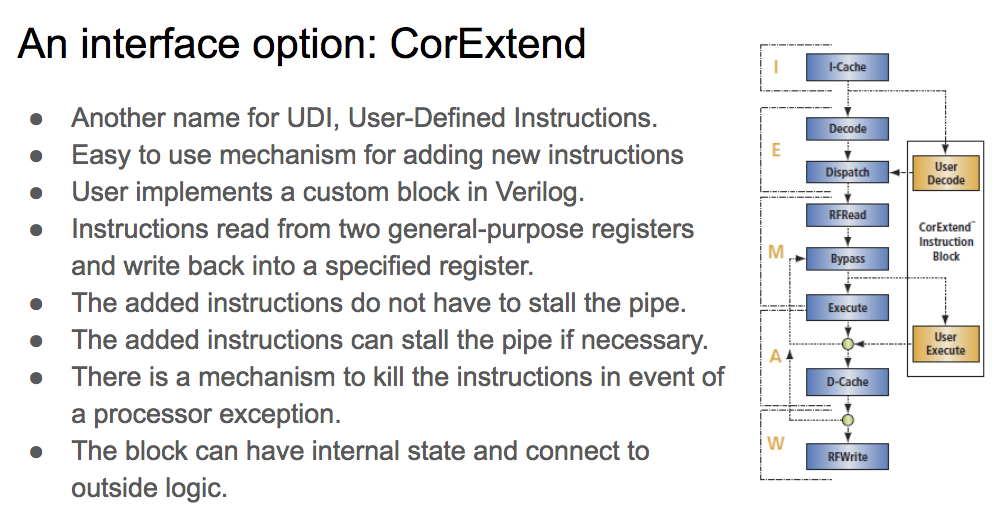
Here is a slide about the mechanism for adding instructions to the MIPS microAptiv UP processor:
At a seminar in Las Vegas on June 4 and probably at the summer school of young electronics engineers, which will be held July 8-26, at MIET in Zelenograd, my daughter Elizabeth Panchul will help me (if she receives a visa in time). Since Elizabeth is semi-sub-semi-Russian / Ukrainian, she speaks only English. Therefore, Russian instructors (students or graduate students of the Moscow Institute of Physics and Technology, Moscow State University, etc., who are ready to help us with Elizabeth and MIET students in conducting the school) can learn the correct English accent, and she from them - the basics of Russian. In addition to learning Verilog, MIPS, architecture, micro-architecture, and organizing DMA into memory when displayed on a graphical screen:
We are waiting for you at all seminars, as well as in committees for creating their programs!
Source: https://habr.com/ru/post/452872/
All Articles