Arduino Thermometer & Hygrometer from E-PAPER to nRF52832 - or what manufacturers have forgotten to release
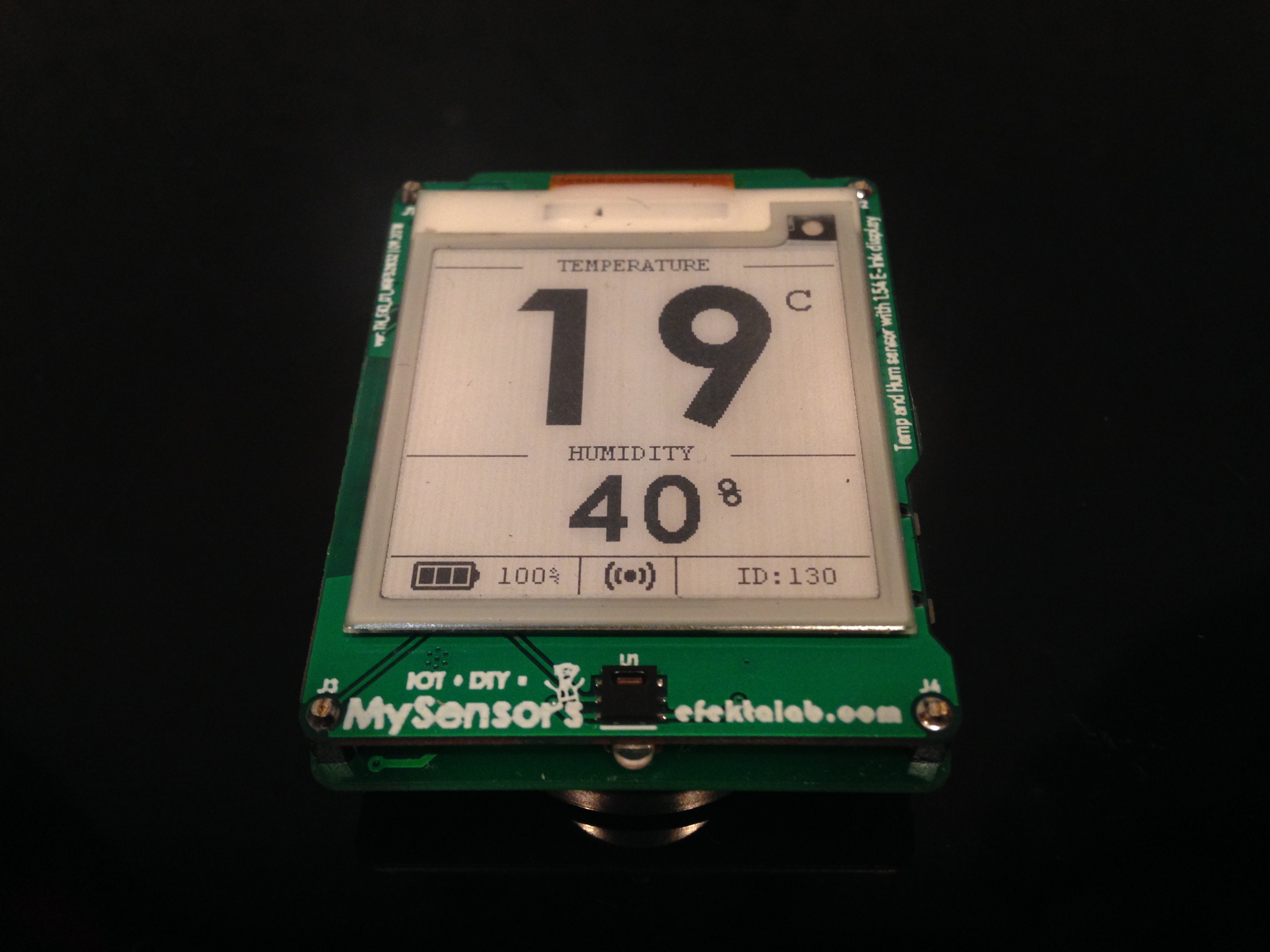
Greetings to all readers of Habr! In my next article I’ll talk again about ARDUINO. I want to share with you my next project implemented on the nRF52832 microcontroller. This is the temperature and humidity sensor on sht20 | ( datasheet ) with a monochrome electronic ink display (E-INK | E-PAPER), which is part of the MySensors ecosystem.

Its main functionality is to monitor the temperature and humidity in the room, sending data to the controller of a smart home or directly to the executive device. Well, additional functionality is just the data output from the sht20 sensor, network information and battery level on the monitor. In my implementation, this is direct interaction directly with the actuator (controller of the heating system circuits). The implementation is non-canonical from the point of view of MySensors, I have added the functionality of a master slave mode, sensor types, air binding. Also in my implementation, the procedure for initialization of the transport level is changed, since MySensors logic is not very good for autonomous devices. But all this is a slightly different story, perhaps worthy of a separate publication, but for now an article about the device in the tradition of the protocol MySensors.
The idea of a device with such functionality matured in the head long ago, the first attempt to implement this idea was made on the atmega328 microcontroller. And in principle, this was done, but I wanted more energy efficiency, more colorful display of information on the display.
')
version atmega 328

When presenting the sensor in the community, they sometimes referred to the Xiaomi device of the company, saying it already exists. But there is a small difference, in Xiaomi it is a gauge, in my case it is the sensor of the smart home system with the function of the gauge. Why display? Just sometimes you just want to turn your head in the direction of the sensor and look at the temperature in the room :).

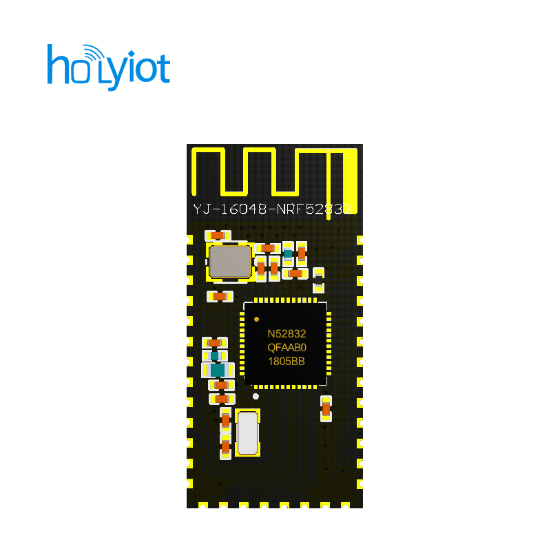
The sensor was implemented on two boards, the scheme for the display was based on the scheme from popular displays Waveshare | Datashit . True, minor changes were made later. The brain of the sensor is the nRF52832 chip in modular implementation from HOLYIOT. The modules themselves deserve special attention, this is the most trouble-free implementation in terms of work in the Arduino IDE. The device used modules - YJ-16048.
The basis of the software implementation of working with the display was taken "instance" distributed on the website Waveshare Electronics. True and there was not without revision.
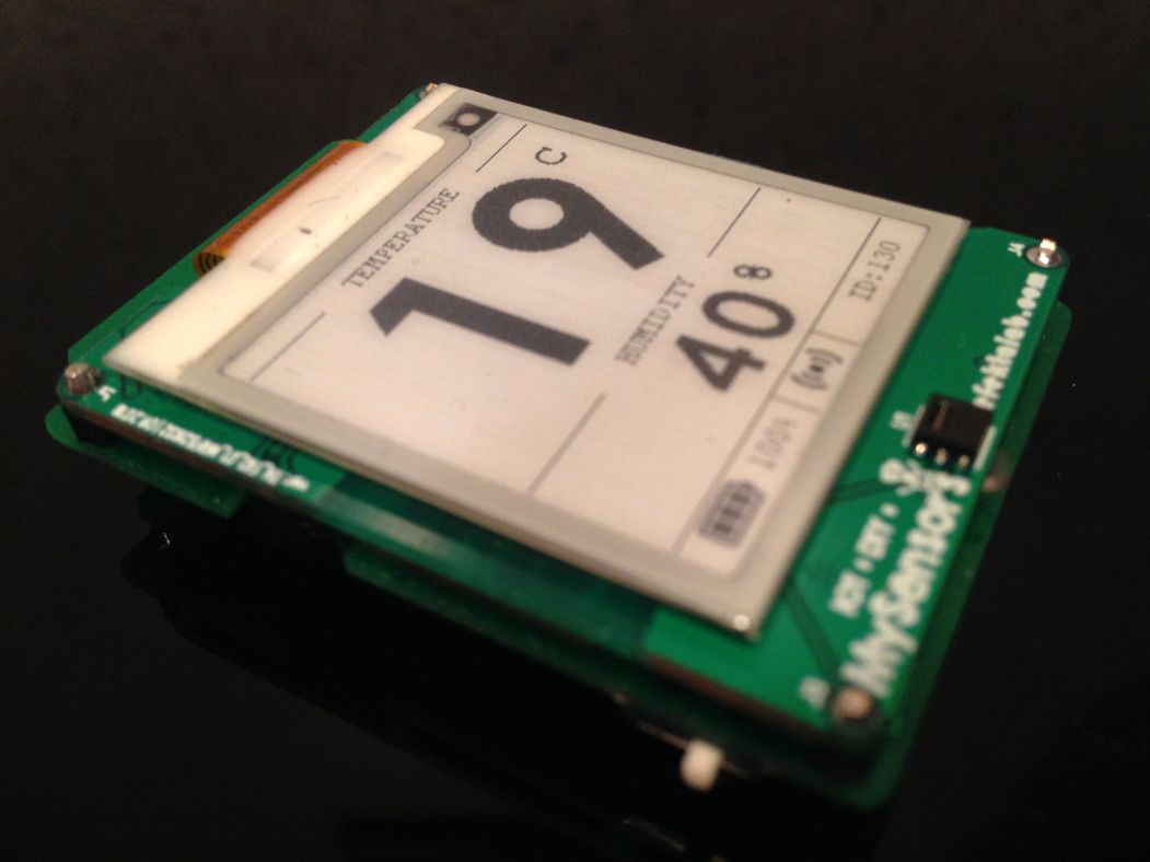
Measurements of the display consumption correspond to those stated in the datasheet, the most important thing is that this display can sleep and the data remain on the screen. True, the display did not turn into a dream immediately, the implementation from Waveshare did not allow this.
The power supply in the sensor is implemented on two cr2450 batteries, reduces to a working 3.3V chip TPS62745DSSR1 with quite good characteristics | datashit At the moment, you can confidently say that this device (the described version) can work for 1 year.
Consumption in the deep sleep mode - ~ 25mkA (with the test program). Average consumption in operating mode ~ 9mA.
The project is open, gerber files are available on the OpenHardWar website, the program code and the library are available by reference ( google drive ). Why not GitHub? It just happened that in the final reazization (v2) it will be there.
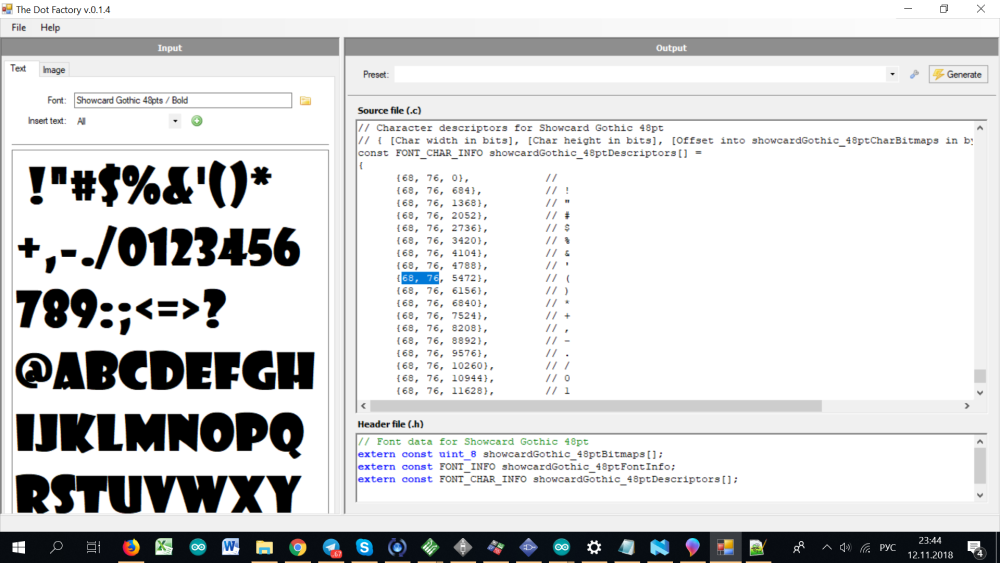
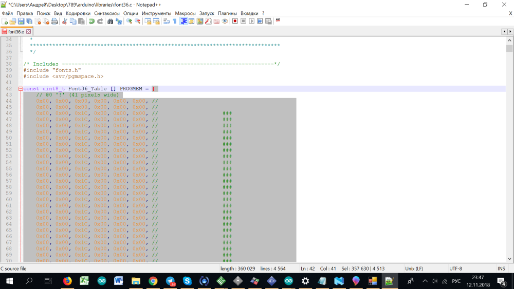
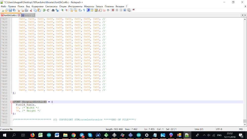
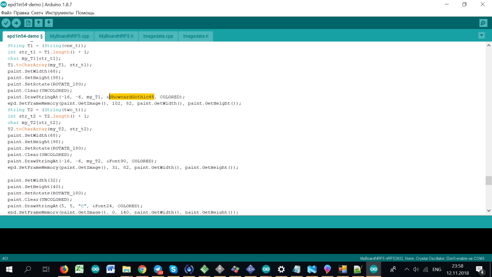
Separate conversation for those who decided to repeat this device deserves the theme of converting characters of the necessary fonts into C arrays. My experience is the conversion using the program TheDotFactory.
Another problem faced by this is updating the information on the screen. On these displays, a partial update of the desired area is available on the screen, which is an absolute plus on the part of energy consumption, but the minus is the appearance of artifacts in the update area of data from previous characters.
But this problem was solved (see program code). The result was:


The video demonstrates the operation of the display.
It shows the update of the data on the screen, after the revision:
This implementation is not final, this project is left for repetition in the form of the Arduino module. The body is not planned for it. Now from this project was born several as a logical continuation. The main differences of the future V2 is powered by a single battery, three-color display, the presence of the case.
An example of running a three-color display:
It is highly recommended (for those who want to repeat) to read my topic on the .org forum for this project (in English). If language is a problem, I’m always happy to help everyone in the chat (installing boards, working with nRF5 microcontrollers in the arduino ide environment, tips on working with the mysensors protocol - @mysensors_eng
Its main functionality is to monitor the temperature and humidity in the room, sending data to the controller of a smart home or directly to the executive device. Well, additional functionality is just the data output from the sht20 sensor, network information and battery level on the monitor. In my implementation, this is direct interaction directly with the actuator (controller of the heating system circuits). The implementation is non-canonical from the point of view of MySensors, I have added the functionality of a master slave mode, sensor types, air binding. Also in my implementation, the procedure for initialization of the transport level is changed, since MySensors logic is not very good for autonomous devices. But all this is a slightly different story, perhaps worthy of a separate publication, but for now an article about the device in the tradition of the protocol MySensors.
The idea of a device with such functionality matured in the head long ago, the first attempt to implement this idea was made on the atmega328 microcontroller. And in principle, this was done, but I wanted more energy efficiency, more colorful display of information on the display.
')
version atmega 328
When presenting the sensor in the community, they sometimes referred to the Xiaomi device of the company, saying it already exists. But there is a small difference, in Xiaomi it is a gauge, in my case it is the sensor of the smart home system with the function of the gauge. Why display? Just sometimes you just want to turn your head in the direction of the sensor and look at the temperature in the room :).
The sensor was implemented on two boards, the scheme for the display was based on the scheme from popular displays Waveshare | Datashit . True, minor changes were made later. The brain of the sensor is the nRF52832 chip in modular implementation from HOLYIOT. The modules themselves deserve special attention, this is the most trouble-free implementation in terms of work in the Arduino IDE. The device used modules - YJ-16048.
The basis of the software implementation of working with the display was taken "instance" distributed on the website Waveshare Electronics. True and there was not without revision.
Measurements of the display consumption correspond to those stated in the datasheet, the most important thing is that this display can sleep and the data remain on the screen. True, the display did not turn into a dream immediately, the implementation from Waveshare did not allow this.
The power supply in the sensor is implemented on two cr2450 batteries, reduces to a working 3.3V chip TPS62745DSSR1 with quite good characteristics | datashit At the moment, you can confidently say that this device (the described version) can work for 1 year.
Consumption in the deep sleep mode - ~ 25mkA (with the test program). Average consumption in operating mode ~ 9mA.
The project is open, gerber files are available on the OpenHardWar website, the program code and the library are available by reference ( google drive ). Why not GitHub? It just happened that in the final reazization (v2) it will be there.
Separate conversation for those who decided to repeat this device deserves the theme of converting characters of the necessary fonts into C arrays. My experience is the conversion using the program TheDotFactory.
I will try to describe the process with pictures :)

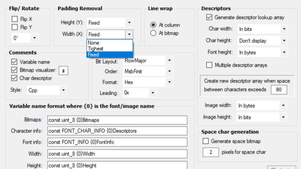


Absolutely any font, you are limited only by the memory capabilities of the nRf52. ... And it makes no sense to store all the characters, If you need only numbers, it saves space very well.
Absolutely any font, you are limited only by the memory capabilities of the nRf52. ... And it makes no sense to store all the characters, If you need only numbers, it saves space very well.
Another problem faced by this is updating the information on the screen. On these displays, a partial update of the desired area is available on the screen, which is an absolute plus on the part of energy consumption, but the minus is the appearance of artifacts in the update area of data from previous characters.
But this problem was solved (see program code). The result was:
The video demonstrates the operation of the display.
It shows the update of the data on the screen, after the revision:
This implementation is not final, this project is left for repetition in the form of the Arduino module. The body is not planned for it. Now from this project was born several as a logical continuation. The main differences of the future V2 is powered by a single battery, three-color display, the presence of the case.
An example of running a three-color display:
It is highly recommended (for those who want to repeat) to read my topic on the .org forum for this project (in English). If language is a problem, I’m always happy to help everyone in the chat (installing boards, working with nRF5 microcontrollers in the arduino ide environment, tips on working with the mysensors protocol - @mysensors_eng
Source: https://habr.com/ru/post/452532/
All Articles