Experiments with analog tunnel diode
In addition to the tunnel diode , it is interesting to conduct a series of experiments with its functional analog, known for several decades. It is like an emulator on a slow gland: there are no real quantum effects, and the speed is not that. But the IVC is the same as the device behavior in the circuit.
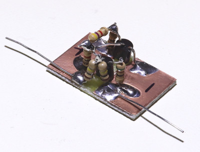
From KDPV, we can conclude that the analog is a two-port network, inside of which there is some simple scheme. Here she is:
')
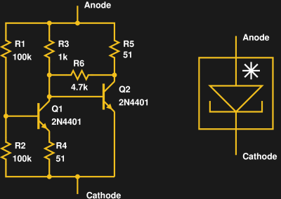
The author tried to use transistors 2N3904 and 2N2222, but it turned out that 2N4401 work better. The properties of the analogue can be varied by selecting the resistor R6. The scheme of the improvised characterographer is still the same:
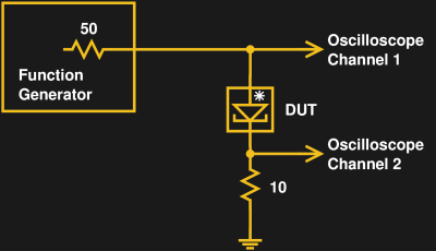
And still it measures the total voltage on the “diode” and the resistor on one channel, and on the other only on the resistor. The voltage drop only on the "diode" can be determined by subtraction. And knowing the voltage across the resistor, you can calculate the current.
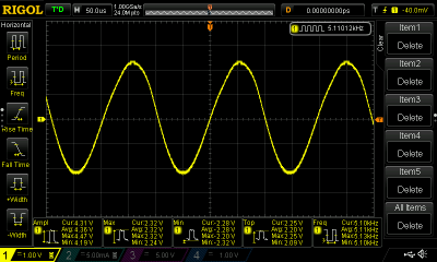
The characterograph works equally regardless of the shape of the oscillations generated by the generator. The frequency of the author put about 100 Hz. The analogue is much "stronger" than a real tunnel diode: you can not be afraid to put it out of action with static, slightly exceeded voltage from the generator, too long soldering. The characteristic turned out to be the following:
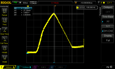
The negative resistance on the almost linear part of the IVC, where it is (from 1.55 to 3.0 V), is approximately equal to -64 Ω. Current with increasing voltage within these limits falls from 27.2 to 4.4 mA. With further increase in voltage, the current slightly increases.
The generator on the analog tunnel diode is obtained if you simply turn on the oscillating circuit in series with it and apply power:
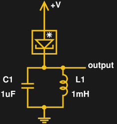
The calculated frequency was equal to 5.033 kHz, the real one - 5.11 kHz. The generator operates in the range of supply voltages from 1.6 to 3.6 V, the best mode of oscillation is obtained at 3.6 V. But at a voltage higher than 2.6 V, the generator does not start up automatically, that is, you must first start it at a lower voltage, which then smoothly increase to optimal. The amplitude of the oscillations exceeds the supply voltage: at 3.5 V it is equal to 4.3 V.
A capacitor parallel to the power supply at such a low frequency is optional.
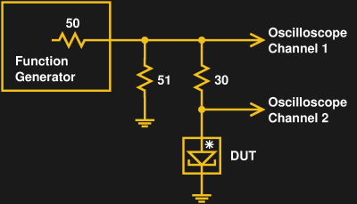
The voltage amplifier on the analog tunnel diode is quite unusual: it is powered by an amplified signal, and the output amplitude is slightly larger than at the input. To get such an amplifier, it is enough to add two resistors to the device: 51 ohm reduces the output impedance of the generator to 25 ohms, 30 ohm - load:
We give rectangular pulses, adjust the amplitude, and suddenly see:
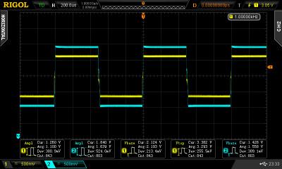
The input amplitude is 1.26 V, the output is 1.84 V.
Of course, the miracle did not happen, the author added to the input signal and adjusted a certain “offset”. Obviously, in the generator it has, there is a function of shifting the signal up by adding a constant component to it. Due to this, the output amplitude turned out to be larger than the input amplitude, although in the circuit there are no capacitances and inductances other than stray ones. But the gain in the variable component is obvious.
Source: https://habr.com/ru/post/452402/
All Articles