Pixel padding in a texture scan
We present the fourth article in our series on working with 3D models in Unity. Previous articles: “Features of working with Mesh in Unity” , “Unity: procedural editing of Mesh” , “Importing 3D-models into Unity and pitfalls” .
In the previous article, we mentioned checking the texture sweep for sufficiency of pixel indentation at a given resolution of the texture. In this publication, we describe the essence of the problem with respect for the pixel indentation and the algorithm for its tracking. It will not be the code, but the principle that can be implemented in any language and in any development environment.
')
An order for a 3D model is usually accompanied by a texture resolution requirement. Due to the discreteness of the raster image, the 3D artist must observe the indent in pixels between the parts of the texture scan. The absence of the necessary indent leads to the fact that the same pixel is displayed on the model in completely different places when it is not needed.
It is especially important to monitor sufficient indentation in the early stages of work. Most often, the creation of geometry, which includes a texture scan, some people are engaged, and the drawing texture - others. The error revealed by a 3D artist will cause less trouble than the one that the texture maker finds. In the latter case, the situation becomes even more complicated if the 3D package you are using does not provide tools for drawing over geometry (for example, a brush).
You should also consider two nuances, because of which between the elements of the sweep may need more space. The first is to reduce the resolution of the texture when mipmapping. The second is the use of a dilation filter when generating a light map . During the execution of the task of creating a UV- scan, the 3D-artist needs to be guided by the requirements for the resolution of the texture, and also take into account the listed nuances. Nevertheless, many shortcomings simply do not notice without automated verification.
An example of the appearance of artifacts with reduced detail
For simple models, a texture scan can be formed using automatic tools. However, they are based on internal metrics and do not take into account pixel indentation, so shared pixels are often located along diagonal borders. Checking with texture checkers does not show all errors, in addition, these textures often have a higher resolution than those used in the project.

Shared pixels
The problem of insufficient pixel indentation in the UV scan looks like a problem with overlays. In both cases, the so-called bleeding can occur - in the previous article we described what artifacts this gives rise to.
However, the problem with pixel indentation depends on the requirement for the minimum resolution of the texture. To determine overlays, a one-time check is sufficient, while the requirements for texture resolution may change at the next stage of development. The situation is complicated by the fact that in the 3D packages we use there are no tools for automatic detection of errors related to the proximity of parts of the UV scan. And do not forget that after the work of the automatic driver in Unity, you need to check UV2 .
We decided to create a tool that can perform indentation checking in pixels and mark potential defects on the model. Indent requirements will be determined based on the following parameters:
Since the sizes of the textures used by us are equal to powers of two, the formula for calculating the necessary indentation at basic resolution is quite simple: (basic Resolution / minimum Resolution) * indent in MinTexture.
Obviously, the solution to this problem is closely related to rasterization. For a clearer formulation of requirements and development of the algorithm, we introduce several concepts.
Consider a UV- space and a uniform grid of NxM size in the range of 0.0–1.0. Cells with a width of 1 / N and a height of 1 / M form a partition of the UV space.

NxM split UV space
Take two arbitrary points and denote Dn as the number of pixels occupied by the projection on the U axis of the segment connecting the given points. Similarly, Dm for axis V. Then we define the pixel distance as the maximum between Dn and Dm.

Pixel distance
It is worth noting that in the Euclidean space such operations of movement as parallel translation and rotation are not movements for the partitioning grid, if pixel distance is taken as the metric. This nuance has a little complicated development of our decision.

We call a square with a side in K pixels the kernel of K. Then any two points, the pixel distance between which is less than K, can be covered with the core of K.

Examples of nuclei of different sizes
Two edges of a polygon form a concavity of the contour , if their middle point (center of mass at four vertices) lies to the left of these edges when traversing the contour clockwise. To counterclockwise, the condition is to find a point to the right of the edges.

A pair of ribs forming a concavity contour
Now let's talk directly about checking pixel indentation. To implement it, we came up with an algorithm consisting of three independent fragments. The order of execution is not important. The result of each of the fragments is the NxM matrix, which is a buffer of partition cells, where some cells are labeled. Adding all three buffers is a common result.
First consider the simplest fragment. It boils down to finding cells that intersect with close to degenerate triangles and edges whose length is less than the side of the nucleus of a given size. All such cells are marked in the buffer.

The result of checking the dimensions of the elements
Before describing the other two fragments, consider the general logic of their work. Both are associated with the processing of clusters of triangles, called shells or islands. A shell for a 3D artist is a connected set of polygons, that is, each polygon in this set has a neighbor with whom it shares common vertices. Also shell is an independent polygon. Further, under the shell, island and cluster, we mean the same thing.
To find all the shells, we use an algorithm to search for all the connected components of the graph, where the vertex of the graph is represented by a polygon, and the edge is represented by the presence of common vertices of a pair of polygons. Since the only polygon in Unity is a triangle defined by the indices of the vertices, we assume that the triangles are adjacent if at least one index of the vertex of the first coincides with the index of any vertex of the second. From the analogy with the graph and the method of determining the edges, it follows that the set of indices of the vertices of one cluster does not intersect with the set of vertices of the other.
With the common part finished. The second fragment, which we consider, determines the places of potential errors associated with the proximity or overlapping of different clusters.
The input is a set of clusters in the form of sets of triangles in the UV- space, the dimension of the partitioning UV , the corresponding texture resolution (NxM), and the indent P as the number of pixels. For a given splitting, it is necessary to find the areas in which the distance in pixels between the clusters is less than the required indent. A cell in the result matrix is flagged if it is included in at least one kernel of K = P + 1 , which intersects two different clusters.
The essence of the fragment is almost described in the description of the result. It is necessary to find all the kernels of K , which intersect with triangles from different shells, and then mark the cells of these kernels in the result buffer.
In our implementation, all pairs of clusters are considered in turn. For each pair, the area of intersection of sets of kernels of quantity K covered by these clusters is determined. Choose a pair and denote such a set as Q.
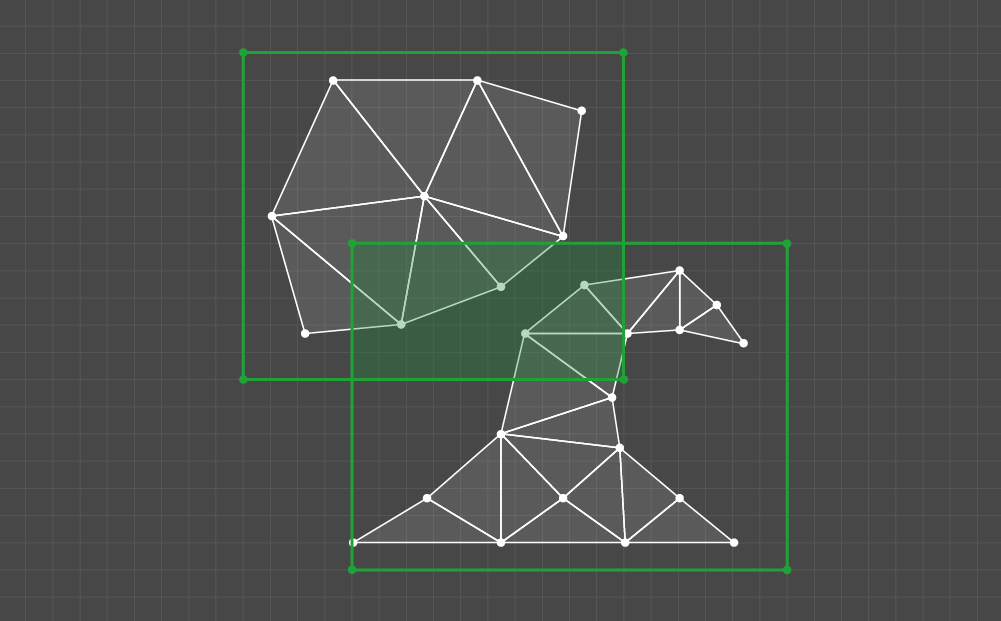
Then all elements of Q need to be checked by the following criterion: does the given kernel intersect at least one triangle in each of the clusters of the selected pair. If so, then all cells of the scanned kernel are marked.
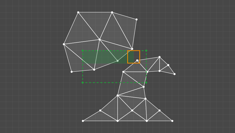
The buffer with labeled cells for all pairs of clusters and is the result.

The result of checking the indentation between the clusters
Now let's deal with the last fragment. Here it is necessary to process one cluster. The input is a set of triangles in the UV space, the dimension of the partitioning UV , the corresponding texture resolution (NxM), and the indent P as the number of pixels. A cell can be marked in two cases: either the cluster is invalid or has holes, or the distance in pixels between the edges of the concavities is less than the required indent.
The inner part of the cluster does not interest us - first we get its outline, represented by a linked list of edges. Neighboring triangles duplicate the indices of the vertices, so the edge belongs to the contour if the pair of indices of its vertices is unique to the set of edges of the cluster. Having found out which edges form a contour, it is necessary to arrange them in such a way that a coherent list is obtained.
If after this step not all edges of the contour are in the list, then either the cluster has holes, or there is an error in the mesh data. In this case, it is necessary to properly mark all the cells of the nuclei intersected by the cluster.
If the contour is found, then processing continues. We formulated the following result requirement. Let a pair of edges forming a concavity of the contour intersect the kernel of the quantity K = P + 1 . Then the cells of the nucleus must be marked if both parts of the contour between the edges go beyond the limits of this nucleus.

Cluster features check result
We decided to implement this requirement through a pairwise comparison of the edges of the contour. We start with the concavity condition, then for each pair all the nuclei that intersect both edges are checked. To check the kernel, rounds of each part of the contour are performed between a pair of edges. If each part contains at least one point beyond the boundaries of the core, then all the cells of the core are marked.

The condition for marking the cells of the scanned kernel
The algorithm is very well suited for implementation using parallel computing. Processing of each pair of clusters and edges occurs independently. Since the checks are based on rasterization, if you start processing not with a pair of edges, but with cores, then it is advisable to use the GPU features.
We convert the result of the algorithm into texture. For a given resolution, this allows you to graphically show the locations of potential deficiencies in the UV scan. Also, the resulting texture can be superimposed on the model to see the marks directly on the geometry.
In the examples below, we specifically cut the rabbit and Suzanna with the automatic Blender tool so as to get more artifacts. The checked texture resolution is 256x256, the required indent is 1.
Cells marked in blue cover clusters with holes, as well as triangles and edges that are too small. Cells of nuclei with features of each cluster separately are marked green. Kernels in which the indentation between the clusters is not observed are marked in red.
In the next article, we will look at the algorithm for optimizing 3D models in a scene by removing invisible geometry. Stay with us!
In the previous article, we mentioned checking the texture sweep for sufficiency of pixel indentation at a given resolution of the texture. In this publication, we describe the essence of the problem with respect for the pixel indentation and the algorithm for its tracking. It will not be the code, but the principle that can be implemented in any language and in any development environment.
')
Problematics
An order for a 3D model is usually accompanied by a texture resolution requirement. Due to the discreteness of the raster image, the 3D artist must observe the indent in pixels between the parts of the texture scan. The absence of the necessary indent leads to the fact that the same pixel is displayed on the model in completely different places when it is not needed.
It is especially important to monitor sufficient indentation in the early stages of work. Most often, the creation of geometry, which includes a texture scan, some people are engaged, and the drawing texture - others. The error revealed by a 3D artist will cause less trouble than the one that the texture maker finds. In the latter case, the situation becomes even more complicated if the 3D package you are using does not provide tools for drawing over geometry (for example, a brush).
You should also consider two nuances, because of which between the elements of the sweep may need more space. The first is to reduce the resolution of the texture when mipmapping. The second is the use of a dilation filter when generating a light map . During the execution of the task of creating a UV- scan, the 3D-artist needs to be guided by the requirements for the resolution of the texture, and also take into account the listed nuances. Nevertheless, many shortcomings simply do not notice without automated verification.
An example of the appearance of artifacts with reduced detail
For simple models, a texture scan can be formed using automatic tools. However, they are based on internal metrics and do not take into account pixel indentation, so shared pixels are often located along diagonal borders. Checking with texture checkers does not show all errors, in addition, these textures often have a higher resolution than those used in the project.
Shared pixels
The problem of insufficient pixel indentation in the UV scan looks like a problem with overlays. In both cases, the so-called bleeding can occur - in the previous article we described what artifacts this gives rise to.
However, the problem with pixel indentation depends on the requirement for the minimum resolution of the texture. To determine overlays, a one-time check is sufficient, while the requirements for texture resolution may change at the next stage of development. The situation is complicated by the fact that in the 3D packages we use there are no tools for automatic detection of errors related to the proximity of parts of the UV scan. And do not forget that after the work of the automatic driver in Unity, you need to check UV2 .
We decided to create a tool that can perform indentation checking in pixels and mark potential defects on the model. Indent requirements will be determined based on the following parameters:
- The basic resolution of the texture.
- The minimum resolution of the texture at which no leakage is allowed.
- The required amount of indentation on the minimum texture.
Since the sizes of the textures used by us are equal to powers of two, the formula for calculating the necessary indentation at basic resolution is quite simple: (basic Resolution / minimum Resolution) * indent in MinTexture.
Obviously, the solution to this problem is closely related to rasterization. For a clearer formulation of requirements and development of the algorithm, we introduce several concepts.
Key Concepts
Consider a UV- space and a uniform grid of NxM size in the range of 0.0–1.0. Cells with a width of 1 / N and a height of 1 / M form a partition of the UV space.
NxM split UV space
Take two arbitrary points and denote Dn as the number of pixels occupied by the projection on the U axis of the segment connecting the given points. Similarly, Dm for axis V. Then we define the pixel distance as the maximum between Dn and Dm.
Pixel distance
It is worth noting that in the Euclidean space such operations of movement as parallel translation and rotation are not movements for the partitioning grid, if pixel distance is taken as the metric. This nuance has a little complicated development of our decision.
We call a square with a side in K pixels the kernel of K. Then any two points, the pixel distance between which is less than K, can be covered with the core of K.
Examples of nuclei of different sizes
Two edges of a polygon form a concavity of the contour , if their middle point (center of mass at four vertices) lies to the left of these edges when traversing the contour clockwise. To counterclockwise, the condition is to find a point to the right of the edges.
A pair of ribs forming a concavity contour
Decision
Now let's talk directly about checking pixel indentation. To implement it, we came up with an algorithm consisting of three independent fragments. The order of execution is not important. The result of each of the fragments is the NxM matrix, which is a buffer of partition cells, where some cells are labeled. Adding all three buffers is a common result.
First consider the simplest fragment. It boils down to finding cells that intersect with close to degenerate triangles and edges whose length is less than the side of the nucleus of a given size. All such cells are marked in the buffer.
The result of checking the dimensions of the elements
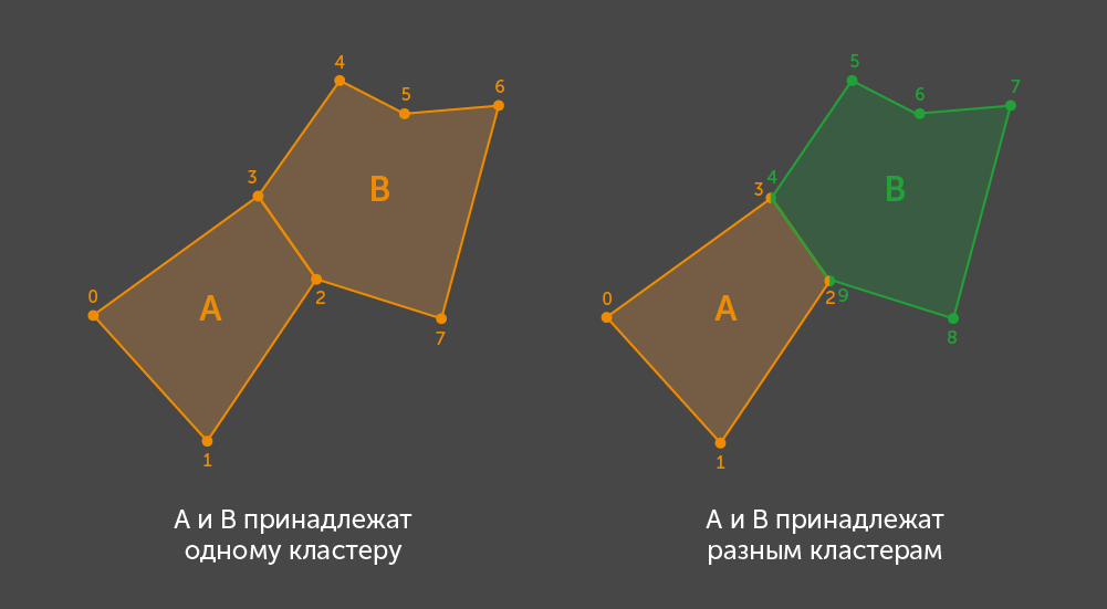
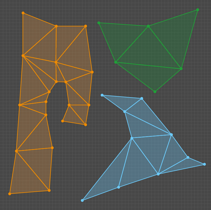
Before describing the other two fragments, consider the general logic of their work. Both are associated with the processing of clusters of triangles, called shells or islands. A shell for a 3D artist is a connected set of polygons, that is, each polygon in this set has a neighbor with whom it shares common vertices. Also shell is an independent polygon. Further, under the shell, island and cluster, we mean the same thing.
To find all the shells, we use an algorithm to search for all the connected components of the graph, where the vertex of the graph is represented by a polygon, and the edge is represented by the presence of common vertices of a pair of polygons. Since the only polygon in Unity is a triangle defined by the indices of the vertices, we assume that the triangles are adjacent if at least one index of the vertex of the first coincides with the index of any vertex of the second. From the analogy with the graph and the method of determining the edges, it follows that the set of indices of the vertices of one cluster does not intersect with the set of vertices of the other.
With the common part finished. The second fragment, which we consider, determines the places of potential errors associated with the proximity or overlapping of different clusters.
The input is a set of clusters in the form of sets of triangles in the UV- space, the dimension of the partitioning UV , the corresponding texture resolution (NxM), and the indent P as the number of pixels. For a given splitting, it is necessary to find the areas in which the distance in pixels between the clusters is less than the required indent. A cell in the result matrix is flagged if it is included in at least one kernel of K = P + 1 , which intersects two different clusters.
The essence of the fragment is almost described in the description of the result. It is necessary to find all the kernels of K , which intersect with triangles from different shells, and then mark the cells of these kernels in the result buffer.
In our implementation, all pairs of clusters are considered in turn. For each pair, the area of intersection of sets of kernels of quantity K covered by these clusters is determined. Choose a pair and denote such a set as Q.
Then all elements of Q need to be checked by the following criterion: does the given kernel intersect at least one triangle in each of the clusters of the selected pair. If so, then all cells of the scanned kernel are marked.
The buffer with labeled cells for all pairs of clusters and is the result.
The result of checking the indentation between the clusters
Now let's deal with the last fragment. Here it is necessary to process one cluster. The input is a set of triangles in the UV space, the dimension of the partitioning UV , the corresponding texture resolution (NxM), and the indent P as the number of pixels. A cell can be marked in two cases: either the cluster is invalid or has holes, or the distance in pixels between the edges of the concavities is less than the required indent.
The inner part of the cluster does not interest us - first we get its outline, represented by a linked list of edges. Neighboring triangles duplicate the indices of the vertices, so the edge belongs to the contour if the pair of indices of its vertices is unique to the set of edges of the cluster. Having found out which edges form a contour, it is necessary to arrange them in such a way that a coherent list is obtained.
If after this step not all edges of the contour are in the list, then either the cluster has holes, or there is an error in the mesh data. In this case, it is necessary to properly mark all the cells of the nuclei intersected by the cluster.
If the contour is found, then processing continues. We formulated the following result requirement. Let a pair of edges forming a concavity of the contour intersect the kernel of the quantity K = P + 1 . Then the cells of the nucleus must be marked if both parts of the contour between the edges go beyond the limits of this nucleus.
Cluster features check result
We decided to implement this requirement through a pairwise comparison of the edges of the contour. We start with the concavity condition, then for each pair all the nuclei that intersect both edges are checked. To check the kernel, rounds of each part of the contour are performed between a pair of edges. If each part contains at least one point beyond the boundaries of the core, then all the cells of the core are marked.
The condition for marking the cells of the scanned kernel
Results
The algorithm is very well suited for implementation using parallel computing. Processing of each pair of clusters and edges occurs independently. Since the checks are based on rasterization, if you start processing not with a pair of edges, but with cores, then it is advisable to use the GPU features.
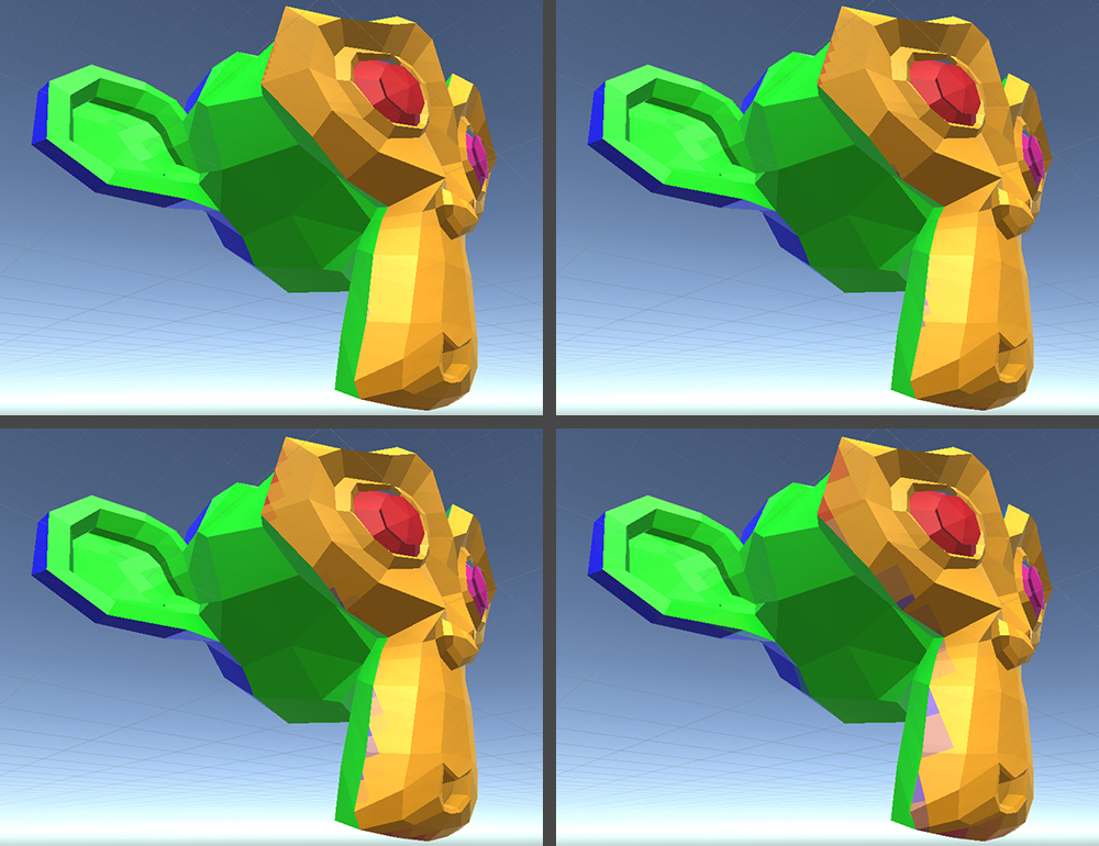
We convert the result of the algorithm into texture. For a given resolution, this allows you to graphically show the locations of potential deficiencies in the UV scan. Also, the resulting texture can be superimposed on the model to see the marks directly on the geometry.
In the examples below, we specifically cut the rabbit and Suzanna with the automatic Blender tool so as to get more artifacts. The checked texture resolution is 256x256, the required indent is 1.
Cells marked in blue cover clusters with holes, as well as triangles and edges that are too small. Cells of nuclei with features of each cluster separately are marked green. Kernels in which the indentation between the clusters is not observed are marked in red.
Examples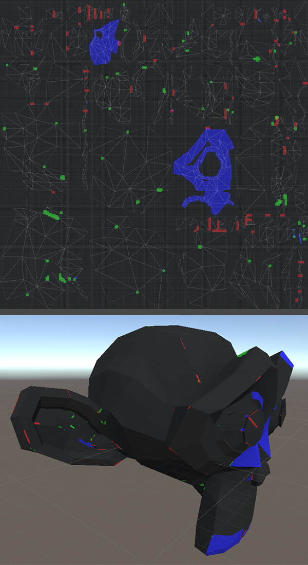

In the next article, we will look at the algorithm for optimizing 3D models in a scene by removing invisible geometry. Stay with us!
Source: https://habr.com/ru/post/451794/
All Articles