Ultrasound gps
Ultrasound GPS. Conceptual model
Before you go on such a long voyage it is worth checking out, and is it really possible to do everything on your knee?
What this article is about: how to quickly and inexpensively make a simple ultrasound GPS.
List of required devices
- HC-SR04 3 pcs.
- Arduino 1 pc
- Coil of wires.
Concept
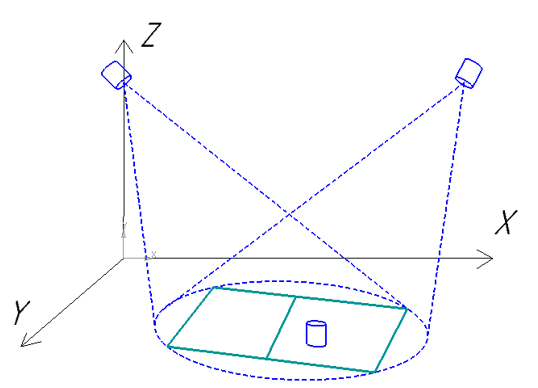
Fig. 1 - The general idea of the device
HC-SR04, which play the role of emitters, is installed in the upper corners of the room, the third receiver is on the floor of the receiver, it plays the role of receiver.
')
All this is connected according to the scheme:
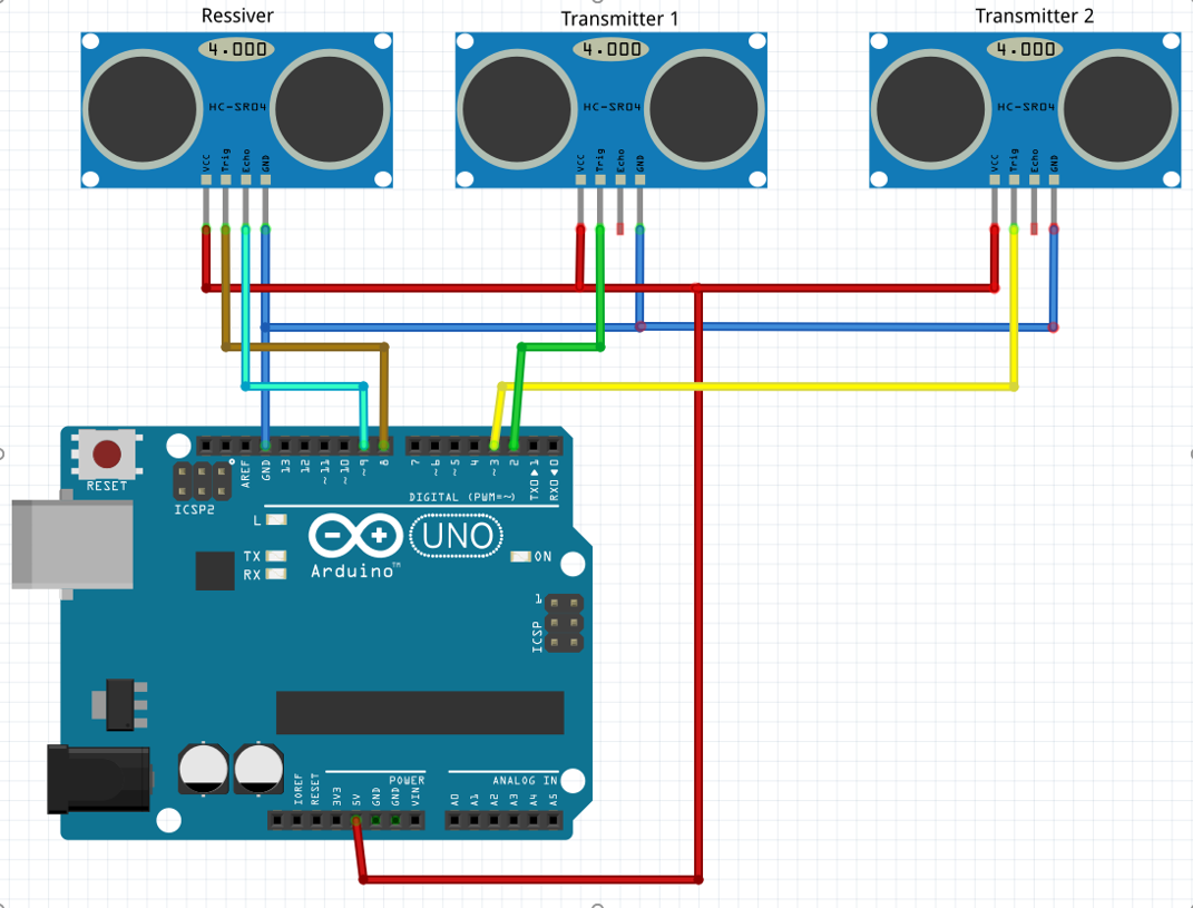
Fig. 2 - Device Connection Diagram
And of course you connect the Arduino via USB to a computer.
How it all works:
- Measure the distance from the receiver to the radiator 1
- Send a signal to start measuring the distance to the receiver and emitter 1 (pull the Trig tabs with it).
- Wait until the receiver gives us the length.
- Repeat the same for emitter 2.
- Calculate the coordinates of the receiver.
Recall the school geometry
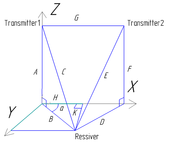
Fig. 3 - Geometric representation of the problem
On the basis of this figure we make the formula for calculating the coordinates:
A, F - height of the emitters relative to the receiver;
C, E - the lengths obtained when measuring the distance from the emitters to the receiver;
G is the distance between the radiators.
Practice
Install two emitters under the ceiling, at a decent distance from each other (3 meters), direct them with emitters to one point, around which your work area will be formed.
Fix the receiver on something flat (for example, a piece of board) and roll an emitter with adhesive tape to it so that we do not create excessive ultrasonic noise in the room.
Connect everything according to the scheme presented above.
Something like this might look like fasteners for emitters and a substrate for the receiver:
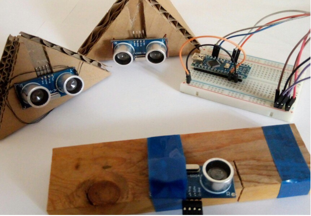
Fig. 4 - Type of modules
Program
Consider the key parts of the code in more detail.
We force the emitter 1 and the receiver to start measuring the distance by switching the Trig input of these devices from low to high, 10 microseconds and back to low.
digitalWrite(trigPinRessiv, LOW); digitalWrite(trigPinTransmit1, LOW); delayMicroseconds(5); digitalWrite(trigPinRessiv, HIGH); digitalWrite(trigPinTransmit1, HIGH); delayMicroseconds(10); digitalWrite(trigPinRessiv, LOW); digitalWrite(trigPinTransmit1, LOW); Usually, these devices emit an ultrasonic signal themselves and wait until it is reflected from something, and come back to them. But we are deceiving them, in our case, one sends and the other receives, the one that received thinks that this is his signal, although this is a signal from another device, and gives us the distance to this other device.
We are waiting until the sensor begins to tell us the duration of the flight of the ultrasonic signal:
while (digitalRead(echoPinRessiv) == LOW); Record the time to start receiving the signal:
timeStartSignal = micros(); We are waiting until the sensor stops telling us the time of flight of the ultrasonic signal:
while (digitalRead(echoPinRessiv) == HIGH); Write the end time:
timeEndSignal = micros(); According to a simple formula, we calculate the distance from the emitter to the receiver:
lenC = ((timeEndSignal-timeStartSignal)/58.00)*10.00; We are waiting until it stops in the room ultrasonic noise:
delay(100); It should be noted that the sensor tells us the distance by lowering the Echo output to Low for a period of time directly proportional to the measured distance.
We repeat the same for the second radiator.
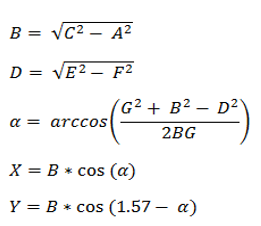
Using the rules of a rectangular triangle, we project the resulting distance onto the floor plane (Fig. 3).
We implement the formula for the transition from the three-dimensional coordinates to the plane, the formula is presented above:
lenB = sqrt((lenC*2.00)*(lenC*2.00) - lenA*lenA); Unfortunately, we have errors and to remove them, I derived just such an experimental formula, delete it and see what you get.
measurementError = 26.437 - 0.08*lenC/10; lenB = (lenB + measurementError*10)/10.00; The same is repeated for sensor 2
Calculate the coordinates on the plane
Find the angle Alpha:
alfa = acos(((lenG*lenG + lenD*lenD - lenB*lenB)*1.00) / ((2*lenE*lenG)*1.00)); Find the coordinates themselves:
koord_X = lenE*cos(1.57-alfa); koord_Y = lenE*cos(alfa); If the value of the coordinates is beyond the limits of the possible then replace it with the previous value:
if((koord_X > 0) && (koord_X < 500) && (koord_Y > 0) && (koord_Y < 500)) { oldKoord_X = koord_X; oldKoord_Y = koord_Y; }else{ koord_X = oldKoord_X; koord_Y = oldKoord_Y; } We make a buffer for 6 coordinate values and constantly shift it:
koord_X5 = koord_X4; koord_X4 = koord_X3; koord_X3 = koord_X2; koord_X2 = koord_X1; koord_X1 = koord_X; koord_Y5 = koord_Y4; koord_Y4 = koord_Y3; koord_Y3 = koord_Y2; koord_Y2 = koord_Y1; koord_Y1 = koord_Y; We get the average of the last 6 measurements:
averageKoord_X = (koord_X + koord_X1 + koord_X2 + koord_X3 + koord_X4 + koord_X5)/6; averageKoord_Y = (koord_Y + koord_Y1 + koord_Y2 + koord_Y3 + koord_Y4 + koord_Y5)/6; We send coordinates to the PC:
Serial.println(averageKoord_X); Serial.println(averageKoord_Y); Functions:
float asin(float c) float acos(float c) float atan(float c) just take and use =)
All code in its entirety:
int trigPinRessiv = 8; int echoPinRessiv = 9; int trigPinTransmit1 = 2; int trigPinTransmit2 = 3; int i; long lenA = 2700; //sensor height in mm long lenG = 305; // distance between sensors in cm long koord_X, koord_Y; long koord_X1, koord_Y1; long koord_X2, koord_Y2; long koord_X3, koord_Y3; long koord_X4, koord_Y4; long koord_X5, koord_Y5; long oldKoord_X = 0, oldKoord_Y = 0; long averageKoord_X, averageKoord_Y; long measurementError; float alfa; long timeStartSignal, timeEndSignal; long lenC, lenE, lenB, lenD; void setup() { Serial.begin (115200); pinMode(trigPinRessiv, OUTPUT); pinMode(echoPinRessiv, INPUT); pinMode(trigPinTransmit1, OUTPUT); pinMode(trigPinTransmit2, OUTPUT); } void loop() { averageKoord_X = 0; averageKoord_Y = 0; digitalWrite(trigPinRessiv, LOW); digitalWrite(trigPinTransmit1, LOW); delayMicroseconds(5); digitalWrite(trigPinRessiv, HIGH); digitalWrite(trigPinTransmit1, HIGH); delayMicroseconds(10); digitalWrite(trigPinRessiv, LOW); digitalWrite(trigPinTransmit1, LOW); while (digitalRead(echoPinRessiv) == LOW); timeStartSignal = micros(); while (digitalRead(echoPinRessiv) == HIGH); timeEndSignal = micros(); lenC = ((timeEndSignal-timeStartSignal)/58.00)*10.00; delay(100); digitalWrite(trigPinRessiv, LOW); digitalWrite(trigPinTransmit2, LOW); delayMicroseconds(5); digitalWrite(trigPinRessiv, HIGH); digitalWrite(trigPinTransmit2, HIGH); delayMicroseconds(10); digitalWrite(trigPinRessiv, LOW); digitalWrite(trigPinTransmit2, LOW); while (digitalRead(echoPinRessiv) == LOW); timeStartSignal = micros(); while (digitalRead(echoPinRessiv) == HIGH); timeEndSignal = micros(); lenE = ((timeEndSignal-timeStartSignal)/58.00)*10.00; delay(100); lenB = sqrt((lenC*2.00)*(lenC*2.00) - lenA*lenA); measurementError = 26.437 - 0.08*lenC/10; lenB = (lenB + measurementError*10)/10.00; lenD = sqrt((lenE*2.00)*(lenE*2.00) - lenA*lenA); measurementError = 26.437 - 0.08*lenD/10; lenD = (lenD + measurementError*10)/10.00; alfa = acos(((lenG*lenG + lenD*lenD - lenB*lenB)*1.00)/((2*lenE*lenG)*1.00)); koord_X = lenE*cos(1.57-alfa); koord_Y = lenE*cos(alfa); if((koord_X > 0) && (koord_X < 500) && (koord_Y > 0) && (koord_Y < 500)) { oldKoord_X = koord_X; oldKoord_Y = koord_Y; }else{ koord_X = oldKoord_X; koord_Y = oldKoord_Y; } koord_X5 = koord_X4; koord_X4 = koord_X3; koord_X3 = koord_X2; koord_X2 = koord_X1; koord_X1 = koord_X; koord_Y5 = koord_Y4; koord_Y4 = koord_Y3; koord_Y3 = koord_Y2; koord_Y2 = koord_Y1; koord_Y1 = koord_Y; averageKoord_X = (koord_X + koord_X1 + koord_X2 + koord_X3 + koord_X4 + koord_X5)/6; averageKoord_Y = (koord_Y + koord_Y1 + koord_Y2 + koord_Y3 + koord_Y4 + koord_Y5)/6; } float asin(float c) { float out; out = ((c+(pow(c,3))/6+(3*pow(c,5))/40+(5*pow(c,7))/112 +(35*pow(c,9))/1152 +(0.022*pow(c,11))+(0.0173*pow(c,13))+(0.0139*pow(c,15)) + (0.0115*pow(c,17))+(0.01*pow(c,19)))); if(c >= .96 && c < .97) { out=1.287+(3.82*(c-.96)); } if(c>=.97 && c<.98) { out=(1.325+4.5*(c-.97)); } if(c>=.98 && c<.99) { out=(1.37+6*(c-.98)); } if(c>=.99 && c<=1) { out=(1.43+14*(c-.99)); } return out; } float acos(float c) { float out; out=asin(sqrt(1-c*c)); return out; } float atan(float c) { float out; out=asin(c/(sqrt(1+c*c))); return out; } So we got the simplest GPS ultrasound system with a scope of meter per meter, the video shows how it all works.
The visualization of the trajectory is done in Matlab, how to do the same visualization I will write in the next article.
In future articles I will consider in more depth the various parts of this system and try to improve them.
I will be glad to hear your opinions and feedback on this topic, the project is still alive =)
Project Page
Inspired by the following sources:
Wikipedia
Post on Habré "Indoor" GPS "with an accuracy of + -2 cm"
Source: https://habr.com/ru/post/451408/
All Articles