How I added car functions on CAN bus, not being able to program

The purpose of this article is to talk about my experience in modifying a car and experimenting with a CAN bus.
How it all started
At first, I decided to add a front camera to my 2017 Chevrolet Cruze. Since the car already has a factory rear view camera, two things needed to be clarified at a high level:
')
- The way to transfer video from the front camera, which I will add.
- A way to display images from the rear view camera on the screen at any time.
The video part was simple. From previous experience, I knew that you can make a switcher on the relay.
The launch on the screen turned out to be more difficult, and after some investigation I came to the conclusion that the car should give a signal from the rear-view camera to the screen via some kind of data bus.
CAN bus
Chevrolet has two different data buses. The first is the standard CAN, fast (500 Kbps) and reliable, it is used for critical data. The second is what GM calls the LAN (GMLAN), the older and slower bus (33.3 Kbps), which is used for non-security data.
I needed a way to listen to traffic over CAN, that is, a sniffer. For this purpose, the PCAN device is incredibly useful.
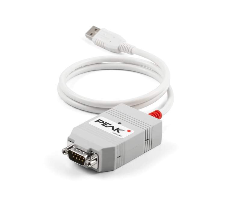
Peak can
Peak Can (PCAN) is a USB device capable of intercepting and transmitting messages. Thanks to the Pcan View software, you can start working without much training.
Since the rear view camera is less important for safety than other components, I assumed that the data sought would most likely be on the GMLAN bus.
The simplest access point is the OBD2 connector. I connected Peak Can to the GMLAN bus, launched the software, and immediately started listening to the traffic.
Integration
The goal was to redesign the rear view camera call. To do this, with the sniffer turned on, I drove the car in reverse so that it turned on the display and then tried to park several times. Throughout this process, I noticed one ID with messages that sequentially imitated my actions.
Then I parked and through Pcan View I tried to transmit the same message that I saw when the display turned on and off. In no time, I had interacted with the bus.
Send a message via PCAN
However, I did not plan to constantly ride with a laptop. We needed a way to automate these functions - and Arduino came in handy here. The ability to directly receive 12V power in combination with a lot of resources and online support has made this choice obvious.
In addition to Arduino, I needed two components to complete the project: a CAN module and a relay module. In essence, Arduino is the brain that runs and executes code. The CAN module provides the ability to interact with the data bus, and the relay provides power to the front camera, and also acts as a video switcher between it and the rear view camera.

Module mcp2515 (top), Arduino Uno (middle), relay module (bottom)
After adding and configuring the appropriate libraries, Arduino has established a connection with the car.
Listening to traffic through Arduino
Since I already knew that I could start the display, I started thinking about HOW to do it. The initial idea was to install a special instant call button on the panel, but I started to think: “And what else can I use on the network as a trigger?”
In the course of the experiments, I found that messages with an ID corresponding to the "Cancel Cruise Control" button are also sent over the GMLAN bus. It was perfect because the cruise control turns on at speeds above 65 km / h when I use the front camera, and at speeds below 15 km / h the rear view camera will turn on to help with parking, so they will never overlap. After writing some code, I was able to force the Arduino to recognize when the cruise control cancel button was pressed.
Recognition of a single button click
However, I didn’t want the camera to be activated every time I cancel the cruise control, so I decided that the best approach is to turn it (essentially) into a multifunction button. The camera is activated only if the button is “double pressed”.
After a long weekend exploring the millis function and debugging the code, I successfully programmed double-click recognition.
Double click recognition
And when I tied it to my teams to control the display, I got a pretty cool small utility.
Double tap + command
Functionality
Now I had the opportunity to turn the display on and off, but there was one problem - what about the rear view camera? I needed them to work together with the front camera, as if they were set up in a factory like that.
In the block diagram, I depicted how I represent it.
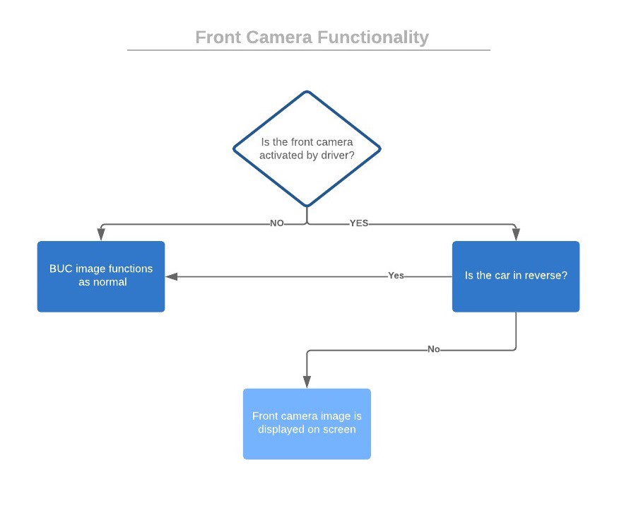
I quickly realized that for such a system you need at any time to know the state of three variables:
- Front camera module: did the driver turn it on or off?
- Camera display: is the display on or off?
- Reverse: is the car in reverse or not?
Having no programming experience, it was very difficult to do, and all my free time I was thinking about different approaches.
In the end, I achieved success!
Active monitoring
Now I was able to implement the operational logic that controls the relay.
Relay Control
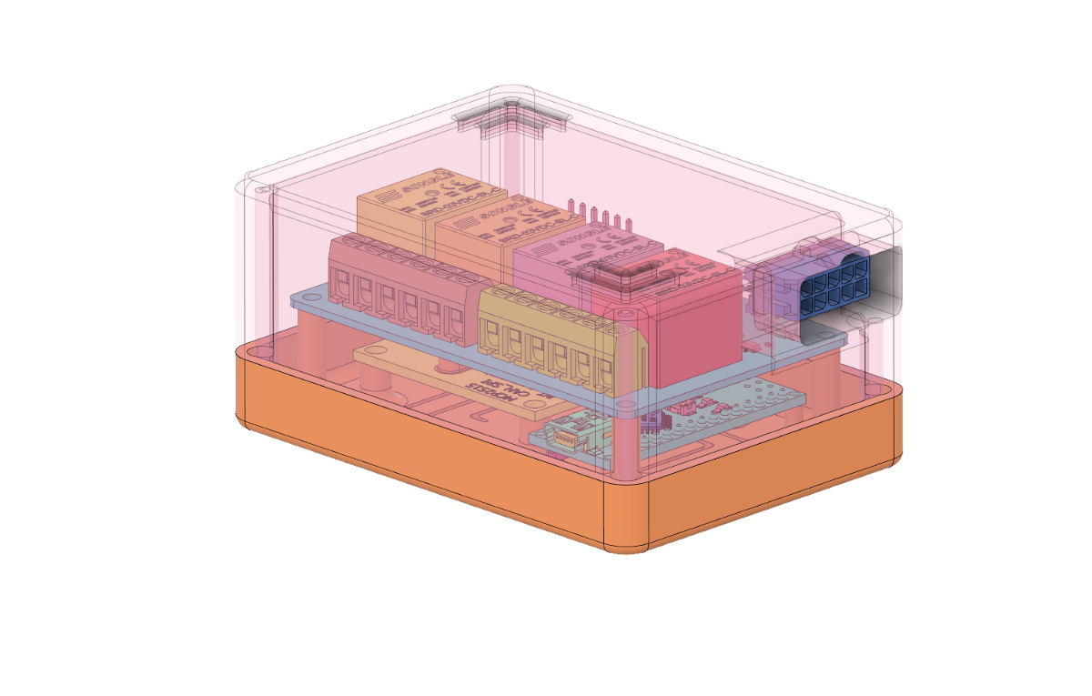
Throughout the process, I learned more and more about the Arduino and noticed that the Nano version was able to do everything that was needed, while it had a smaller size and lower price. It is ideal for permanent installation in the car. I developed a model and printed out a case on a 3D printer to place the components as a compact unit for installation.
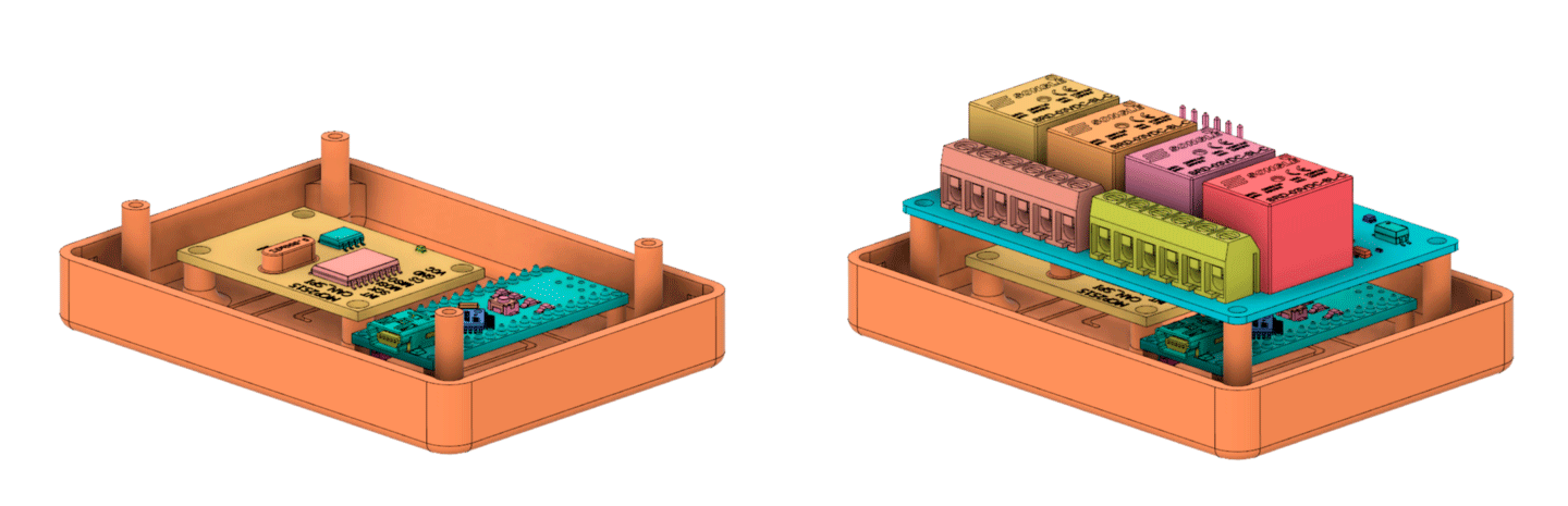
3D case
Together
Finally the day came when I saw the results. Although you still need to tinker with the timing, but it was nice to see that the module works correctly.
Turn on / off the parking mode, turn on / off the front camera, automatically switch to the rear view camera and automatically switch back
In general, this experience taught me a lot and opened my eyes to the possibility of integration directly with the CAN bus. It is quite surprising what can be achieved by connecting two wires.
In future
In the future, I plan to write an in-depth tutorial on how to add additional functionality to existing buttons in your car using free software and components.
Source: https://habr.com/ru/post/451294/
All Articles