I'm not an engineer at my mother
I already lost count of the hours that I spent on making a “small box” and suddenly I caught myself thinking that I was very much in love with engineers - people who can and can design and create new things. Memories of devices, which I understood in my childhood (and not only), immediately rushed to my head. These are funny situations when, when unscrewing the last bolt, like a damn from a snuffbox, several small springs and parts flew out, which were absolutely impossible to pack back.
Once I decided to make a small device (“Security Access Tuner” from Alien: Isolation game) - a controller, a screen, a pair of controls, and pack it all into a small case that was planned to be printed on a 3d printer. Then I could not even think how long it would take for all these little things to come together ...
I have always been attracted to the idea of creating something new - something that is not so often possible to do in everyday life. I do not know what exactly prompted the creation of this particular device, but one day I thought so: “Why not make the security access tuner from the game Alien: Isolation”.
The game has a kind of device for “hacking electronic locks”. This device introduces mini-game mechanics into the game. Here you can choose your own memes, but this is something between “We added games to your game so that you can play games while playing the game” and “We need to go deeper!”. I will not bore you with the details of the gameplay, because anyone can learn about this “beast” in detail by writing the name in your favorite search engine. We just agree that there is some pocket device with games that I decided to implement.
')
In the game, the device looks like this (I tried to accurately reproduce the appearance of the device, but this was not the main task, so the final result is slightly different from the original):
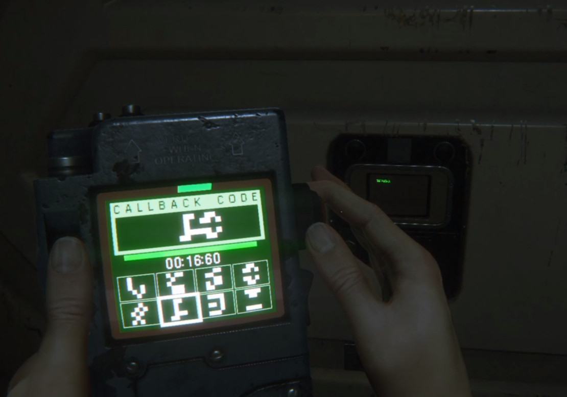
A screenshot from the game, the device is in the hands of the character.
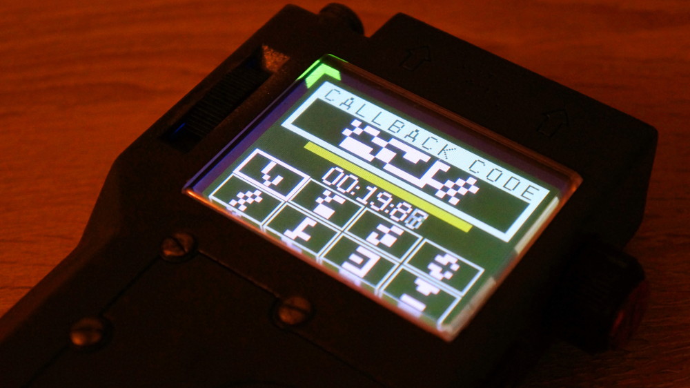
So, you need to make a small device with games and these very “mini-games” - two. In the first (the one on the picture above) you need to select the characters for the allotted time in the order in which they are displayed on the screen. The game is not difficult, if you get used to, but at first makes you think. The second game is a reaction and you just need to press a button in time (I will not focus on it, because there is nothing special in it). In addition to games, there are several more status screens, transitions between games and just “Please wait ...”.
By a lucky coincidence, I had nothing to do with a Texas Instruments Tiva C (Arduino analog) board and the screen for it. And one day, inspiration attacked a person with free time, and for this couple (board and screen) there was a use ...
Development
I immediately decided for myself that the “cherry on the cake” in this idea would not be the program part, but the engineering part. I wanted to make and assemble the device so that everything was compact, functional, logical and convenient (spoiler: everything turned out to be not so simple).
Programming is what I make for bread and I understood that the software part could not provide serious “challenges”. Therefore, in order to bring the idea to life, I began with what is closest to me - from the program part.
Handling events from the buttons and the rotary encoder (rotary encoder) is completely trivial and I see no reason to tell anything about it. Anyhow, the interesting part of the software implementation was the display of graphics on the screen. More precisely, not even the conclusion itself, but rather a set of actions that were necessary for what I wanted to appear on the screen. Basically, the “problem” parts were:
- The memory of the device is limited and many pictures (sprites) in the memory of the device can not be folded.
- The screen works with colors in 565 format (two bytes per color), i.e. for all the graphics, you need to do the conversion to the final format, but due to memory limitations, you will not be able to store all the necessary images in this format in the device’s memory.
- The screen is updated at a staggering frequency of ~ 1 frame per second if it is necessary to redraw the entire screen.
The first two problems were solved relatively simply, because the graphics that need to be displayed on the screen are very primitive (as it is in the game and I decided not to go far from the source material). That is why I immediately decided to use two-color images (sprites), which meant that 8 pixels are placed in one byte and colors can be simply replaced in the output.
On the basis of these same sprites, the entire graphics (including the text) were implemented, except for a couple of exceptions:
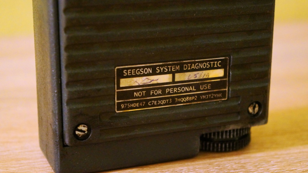
- The logo of a fictional manufacturer company (Seegson), which uses a palette of 16 colors (that is, 2 pixels in one byte). I wanted a little more beauty when I turned on the device and I added it at the very end of development, because there was still some memory left.
- Functions were implemented for drawing graphic primitives (for example, rectangles, and in the interface, which I tried to repeat, there are a lot of them).
The problem of the refresh rate of the screen, it was programmatically not so easy to solve. Especially for places where you need to update the data on the screen quite often.
Fortunately, the problem was not in the screen itself, but in the slow data bus (SPI bus), so you just had to take care of your pants and not walk so widely - just draw what you really need, i.e. "less is better".
The drawing of the interface was divided into three parts to solve the update frequency problem:
- The initial drawing (everything that remains unchanged is drawn here - the background and static interface elements). This stage takes almost a second, but occurs only when the screens are changed, and this second is not so noticeable.
- Animations that do not depend on user actions (countdown timer status, interference, etc.). Usually these are small changes - no more than 15% of the screen, which even in this case allows you to refresh the screen at least 6 times per second (in fact, the refresh rate is much higher and delays are uncompensated). The only exception was the screen with noise - I will tell about it a little lower.
- Animations that depend on user actions (the position of the sliders or the frame around the selected character). These events do not occur as often as with all the desire, the user will not be able to click on the buttons faster than the state is able to redraw the screen.
In simple words, to avoid redrawing the entire screen, only what was necessary was redrawn. For example, if the user chooses the next character on the screen, then the previous “selection” (frame) must be erased (painted over with the background color) and draw a frame in a new place.
Another example of such optimization (where you need to draw a lot, but in fact a little is drawn) is a screen with noise (white noise) - this is the place where the user needs to find the “desired frequency” to get into the mini-game. Interference takes up most of the screen and redrawing all black and white dots would be too long (and silly). Therefore, drawing white noise works as follows:
The screen is divided into two parts (left and right side). Drawing starts from the top.
- Randomly selected part of the screen (left or right side).
- Within this part, a strip of random black and white dots is drawn. This screen has two basic operations for working with it (except for initialization operations) - the operation of writing to the screen buffer and the operation of moving the pointer within this screen buffer itself. And, for some reason I do not understand, the operation of moving the pointer works significantly slower than the write operation. Thus, for this screen, sequential writing to the screen buffer allows you to paint the entire screen in about 0.75 seconds, and performing painting each pixel separately will take almost twice the time (1.4 seconds). It is because of this feature that stripes of black and white dots are drawn, and not just random pixels.
- Go to the next vertical bar on the screen and repeat the steps described in paragraph 1.
When all the vertical lines are drawn, the drawing continues anew from above. As a result of the imposition of some black and white dots on others, it is completely unnoticeable that the screen is essentially “painted in with stripes” like this (first 20 random drawings):

In fact, the interference is not painted over the entire screen, but only those parts where interference is possible (that is, there are several areas on the screen where interference is possible and drawing occurs only within these areas), but this does not change the approach.
The interface needed another rather curious element - an indicator of the selected radio frequency. In order to make it easier to imagine, we can assume that we have an analogue radio in our hands. There is a setting wheel that can be rotated in a circle to find (select) the desired frequency. An indicator of this frequency is drawn on the screen, which can bypass the full circle on the screen and return to its initial position. The indicator in the interface is a triangle (in fact, this is not quite the case, but for simplicity of display, let's agree that it is a triangle) that rotates around one of the vertices located in the center of the screen:

Gray color on the picture marked the borders of the screen.
In fact, this triangle in the interface should not be completely drawn. Only a fragment should be drawn on the screen located in the part of the screen that is farther from the center (at the edges of the screen). Using an example, I showed it in orange:

The gray translucent rectangle in the center is left for clarity, but does not participate in drawing.
The task itself is not difficult, just its solution “head on” with redrawing the entire screen is again unacceptable. Therefore, only separate fragments of the indicator (two beveled borders and a rectangle that connects them) were drawn, and the previous indicator state was “erased” (red in the picture) before drawing:

Those. for this indicator itself, the function of drawing a rectangle was added, which is divided diagonally and filled with two colors (one color on one side relative to the diagonal and another color on the other side). The indicator consisted of two such elements (marked with 1 in the picture) and rectangles connecting them (marked with 2):
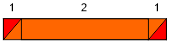
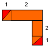
The width (or height) of this element determines the offset relative to the center of the screen. So, when the indicator is in the very center of the screen, only a rectangle (2) is drawn, and as the indicator moves closer to the edge of the screen, the width of the elements (1) increases. When the indicator is located at the edges of the screen, one more rectangle is added when drawing:
Perhaps this is the end of all the “interestingness” of the program part and I can go on to what made me so much respect the engineers ...
Not an engineer
Despite the fact that in my university degree I have written that I am a “computer science engineer,” in fact, I realized that I am “anything computer science,” but not an engineer. I understand that the word “engineer” has a rather broad definition and nowadays it’s very often that the one who is not a manager is an engineer.
Speaking of “engineer”, I mean people who can and can plan, design, design and develop. And in my understanding, I'm not exactly an engineer. In this question I am an amateur - I like to invent and implement something, but I can not say that I always succeed in it. Engineering tasks (we are talking about the case of the device and its main components), which I appreciated as quite simple, took so many hours that I could not imagine. I do not know the exact time, but decided to assume that people did not come up with numbers that could describe such huge quantities.
In childhood, my father often repeated to me the saying “Measure seven times, cut once”. Then I did not fully understand why he said this so often, but it was in the process of creating this device that I realized how important it is to measure it seven times before deciding in favor of one or the other. If I listened to my father, I would not have to do so much trial and error.
So, on the device, on the left side there must be a scroll wheel that can be rotated up (or forward) to select the next character on the screen or rotate down (back) to select the previous character. I decided that I will not do a full scroll wheel, since for a rotary encoder (rotary encoder) or something similar, much more space would be required in the housing, and even for the forward / backward transition, the buttons seemed more logical.
I decided to design the lever in the form of a semicircle, which can be moved up or down. This very lever should have pressed the “up” button or the “down” button and be on some axis to avoid “extra gestures”:
The idea seemed insanely simple to me, but with it there were a lot of questions (to which the people involved in the design of devices would most likely have ready answers) to which I did not have answers. And the questions were the following:
- What and how to attach the buttons? In the picture above, because they simply “hang out in the air” and in the final device this cannot be so.
- Do I need to think about the mechanism for returning the lever to the center? Are springs needed or enough elastic buttons ?.
- How to insert the lever into the case so that the hole in the case was as inconspicuous as possible? Will the lever be one piece or several?
- How will the axis be attached? Will the axis be part of the hull or a separate part?
- How to make sure that what “works on paper” will work after printing on a 3d printer?
And I am sure that there are a lot of ready-made solutions, and the Chinese most likely can order something like "The module of the button of the button of a fashion engineering smell of a woman" in a beautiful box. I know about ready-made tools (editors) for creating similar solutions, but for the sake of sports interest, I decided to “reinvent the wheel”, invent everything myself and get along with only basic tools that were “at hand”.
I invented prototypes of different variants of this lever and tested them in action. I checked the strength of different dimensions of the axis, connections and walls, checked the possibility of creating a lever from several parts (to simplify the placement of the lever in the body). I thought about how it all will fall into the body.
Each time, collecting another prototype, I remembered all these switches / buttons and levers that surround us in everyday life. I had the feeling that I was “a kitten on a laminate” - so far around, in every teapot, everything was so elegant and comfortable, and all my prototypes were kind of clumsy and “not thought out”. Each of my prototype was going “barely” (if it was going at all), i.e. everything seemed to be perfectly assembled, if the dimensions were slightly larger, but you had to invent a solution within the framework of the place that was available in the case. This was the moment I mentioned at the very beginning:
Memories of devices, which I understood in my childhood (and not only), immediately rushed to my head. These amusing situations, when unscrewing the last bolt, like the heck out of the box, several well-placed springs and parts flew out, which it was absolutely impossible to pack back.
There were moments when it began to seem to me that this task was simply impossible to solve. Those. I understood that it was possible, it just seemed to me that I could not think of anything sensible. At such moments I tried to laugh at the situation, to distract and return to the task later, with new forces. In the end, I came to the following answers to my questions (the answers do not pretend to some global truth, but worked for me):
- In the case there will be a separate place for the buttons, the buttons at the bottom will hold the additional part.
- The lever will be returned to the center due to the elasticity of the buttons (the benefit of the lever is very small and its shift relative to the center is not particularly noticeable). In addition, the lever has a very small weight, which allows you not to worry about the button being pressed under the weight of the lever.
- The lever will be one piece (i.e. it will not be assembled from several parts) and it will be inserted from above. The hole will be of such size that one of the “legs” of the lever will pass freely, after which the lever will move to “stick the second leg”.
- The axis will be part of the extra part that will hold the buttons.
- The prototypes made it possible to make sure that it will work in life too, because I actually tested my assumptions as they came.
The lever block was assembled as follows (orange — lever, translucent wall and gray part — parts of a large case, and green — an additional part for fixing the buttons and the axis of the lever):
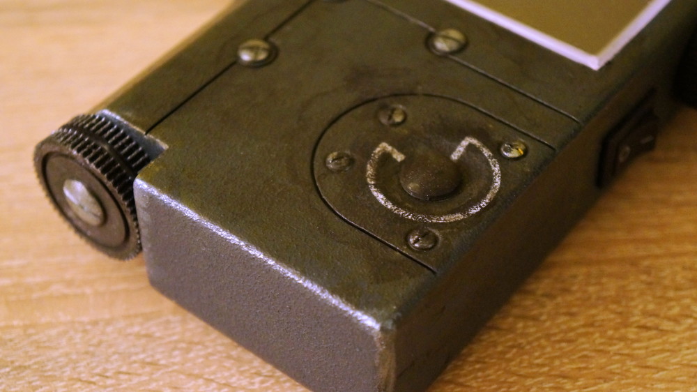
The hole under the lever actually turned out like this and on the final device does not strike the eye:
I guess that this is far from the most elegant engineering solution in the world, but in this decision, I had everything “extinct” to the millimeter. If the width of the part was a little smaller and the strength was not enough, there would be a backlash (and I seriously doubt that working on an even smaller scale would be convenient). If you leave a little more space “for maneuvers” or make the walls of the part a little thicker and the screen does not fit into its rightful place.
I understand that, reading all this, it may seem that this very lever is a very insignificant part of the device, but in fact, almost half of the time that I spent on this whole project, I spent on this lever.
Prototypes
When I tell someone similar stories, people do not take me seriously. The main answer to my statement about my “reduced engineering” was: “Well, what are you telling fairy tales? “After all, everything works, and it looks as good as factory-made!”.
So, I already said that I used only the tools that were at hand. For 3d modeling I used an online editor, which I will not call out loud (so that the post is not considered an ad). This very editor is not very well suited for modeling complex objects, but it completely suits me, because I was familiar with him and could start working right away. If I need to describe its functionality, then I would say that this is MS Paint from the world of 3d modeling - only basic operations, only hardcore. In this editor, it is not possible to directly work with vertices or normals — only with the entire object.
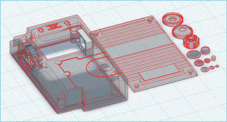
This is how the model that I used to print looks like in this editor:
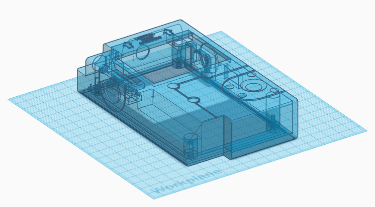
But the devil is in the details, so let's take a look at all the “scars” left by a person with a “non-engineering bone” on an uncomplicated body of the device:
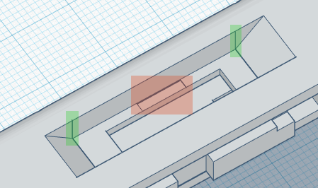
The image shows the location of the lever of which I spoke a little higher.
The recess did not meet the wall borders (the primitives used to create the bevels and the central hole differed in width or simply were not aligned with each other), so the editor displays the lines (marked in green). Red marks the area where, I think (and I'm not sure) there was an old hole for the lever, when I still thought that the lever would consist of several parts.
Of course, this had no effect on the end device, since these are displacements / discrepancies on a scale less than 0.1 mm and the accuracy of 3d printing is not so high as to be noticeable.
Here is another place where a “groove” under the screen was made in the case:
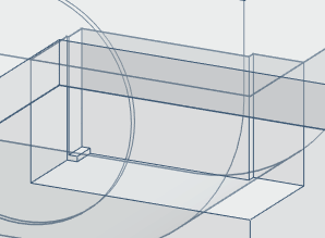
Achivka gets everyone who realized that in general I wanted to show this picture. The groove is inside the case, so the transparency of the model is turned on and the extra lines are visible.
The screen should go into this recess and stay there. This element is needed so that the screen does not hang in the case. Ideally, there should have been a hole (groove) in the shape of an exactly dimensioned parallelepiped, but it is clear that something went wrong and the shape of the recess changed several times. In general, it was necessary to listen to dad and measure out seven times before drawing a groove and would not have to redo it several times. And I know that it would be possible to put all this in order, but by the means of that editor himself is a pain.
Finally, the body cap ... The cap is attached to the body with four M3 bolts. For this, I provided a place for the nuts in the housing:
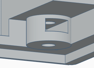
In the image, the bottom view of the body, a rectangular hole - a place under the nut.
Adding these same holes, I proceeded from the thought “how it would be most convenient to make holes in the model”. Knowledgeable people will immediately notice that it was necessary to think about which side it would be more convenient to insert the nut ... As a result, I spent a lot of time trying in the most unnatural way (and this is not my strange preferences, but the stupid arrangement of the holes), tweezers “stick” the nuts in the holes.
And then the artist woke up in me
It was day X when all the preparatory work came to an end and it was time to print out the details, put everything together and paint.
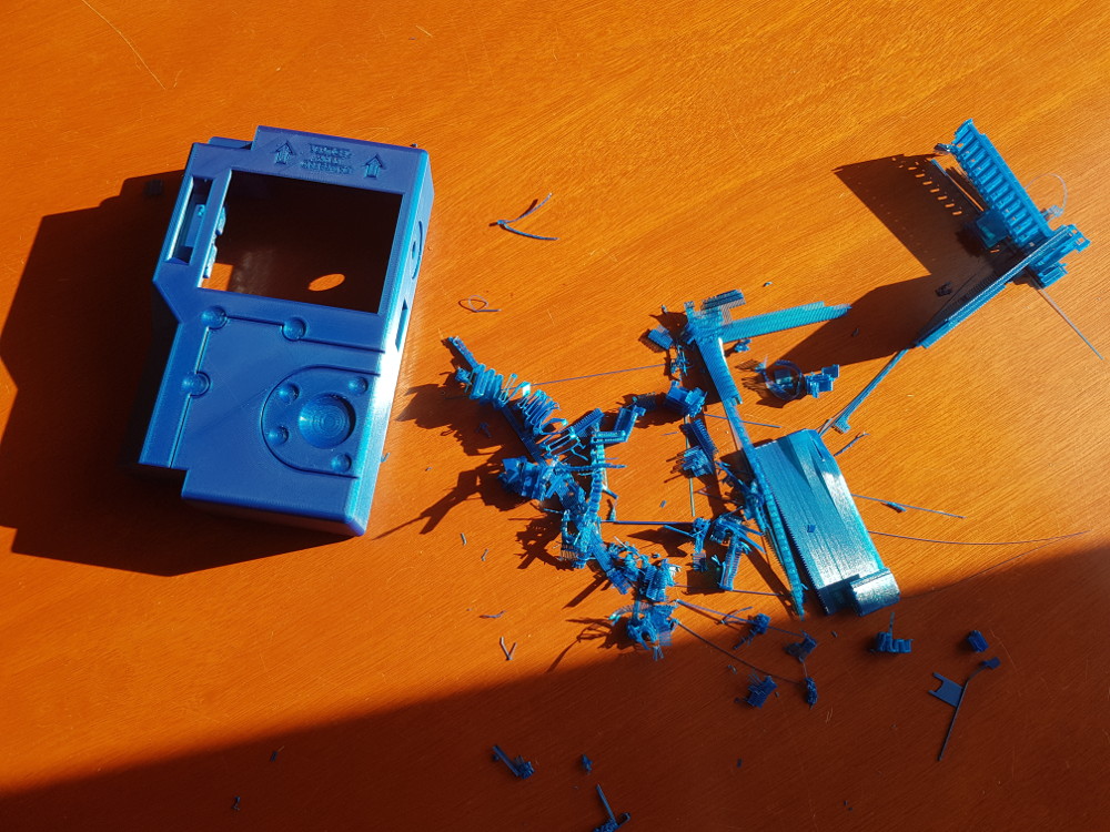
The very first stage is body printing and tearing supports.
As you can see from the photo (and I hope that it can be seen), the print quality is not high enough so that you can simply paint the body, so the next step was my favorite “to modify the file to the desired shape”:
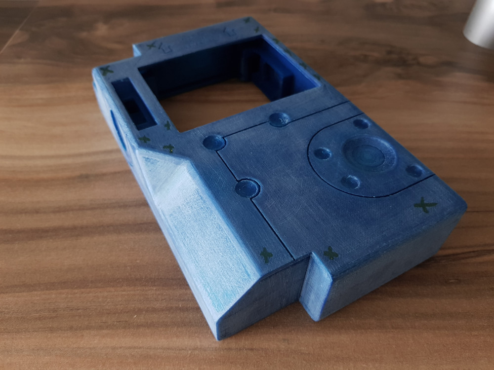
As the grinding of the body, I marked the “problem areas” with crosses.
When the model assumed a normal appearance, it was possible to proceed to painting in two stages. The first step of painting - primer. You can skip this step, but with a primer you can finally align the geometry (remove small scratches) and color.

There are unpainted areas in the grooves, but they will be painted in later.
The funny thing was the selection of colors. It seems that I treat those people who distinguish 7 and a half colors, so the color may differ significantly from what was in the game. Yes, and looking at the screenshots from the Internet, I generally lost faith in my ability to perceive color. It seemed that in every screenshot I saw a new color (shades of gray / blue). I tried to find something similar, and I simply looked for such a color that I would paint a similar device if I produced something like that.
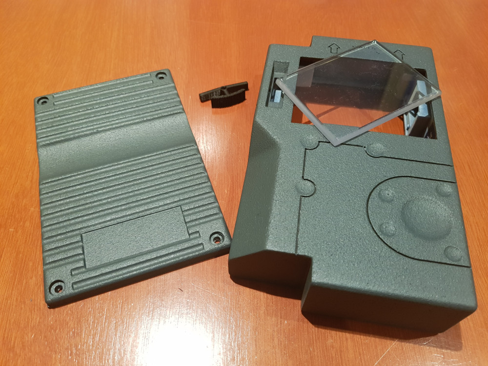
Then there was a protective glass for the screen - plexiglass with stowed edges.
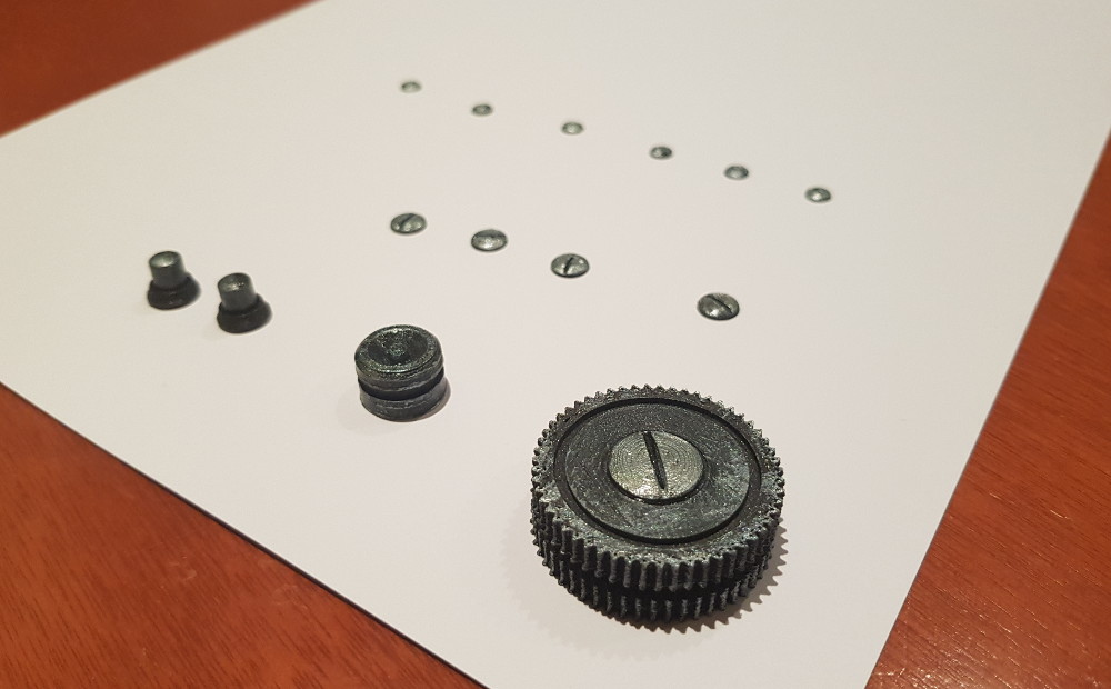
In addition to the case itself, it was necessary to print a scattering of small decorative details that would complement the final appearance of the device:
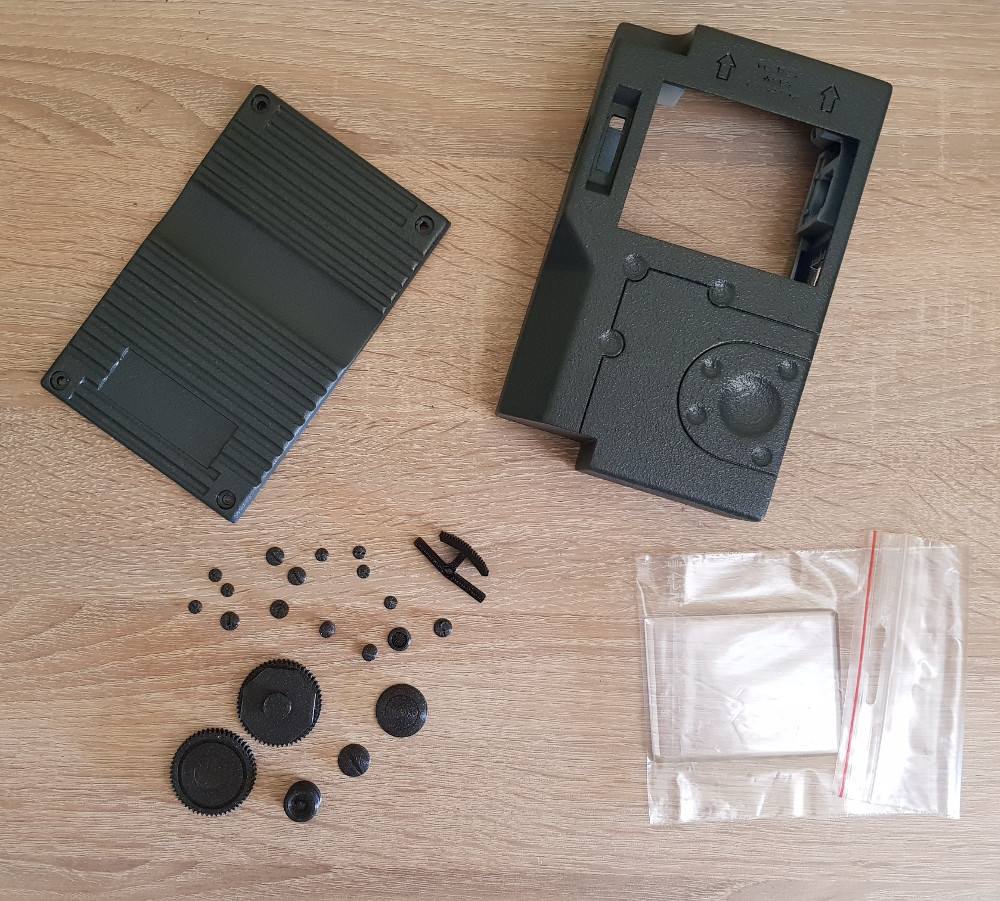
The screen earned a couple of scratches while lying around with the rest of the details, so it was “packed” in polyethylene until better times.
Some parts needed to be glued together and painted, which I did:
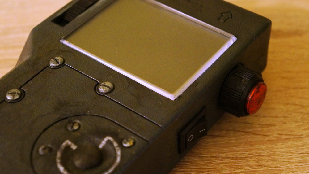
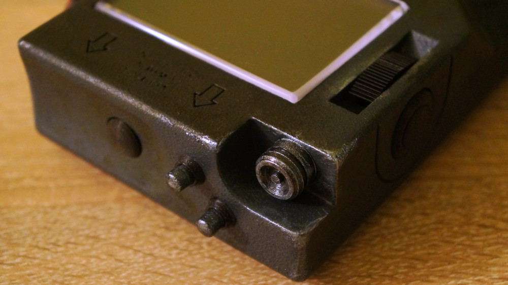
Well, in the end, all the parts were glued to the case and the case was re-painted to pretend that the device was used for many years.
Fans of everything new and brilliant, before viewing the following pictures, I advise you to take a deep breath and maybe even sit down. I’ll say right away that the characters below are completely random and mean nothing. Lovers of conspiracy theories, I ask to relax. Well, a couple of pictures “in work”: Well, it all works like this:


Afterword
In general, as usual, what I would like to say with this story is that one should not be afraid to do something with one's own hands, one should not be afraid to invent something new (read, like “crutches and bicycles”). And even if you have a “non-engineering bone”, you can learn a lot of new things and just have fun.
Sometimes I ask questions to fans of radio electronics and they laugh at how little I understand in electronics. Sometimes I help someone with writing code and smile when I see the source code of people far from programming. Perhaps, reading all this, an engineer smiled somewhere.
Thanks to everyone who read to the end.
Source: https://habr.com/ru/post/451222/
All Articles