Local Autonomous Data Collection System (continued)
Start on this site by reference .
The most convenient option to use the information about the starting of the starter was the option with the PC817 optocoupler.
The boards contain three identical circuits, everything is placed in ABS plastic boxes, size 100x100 mm.
')
When connected to the starters with semiconductor valves, their leakage current is sufficient for opening the PC817 and there will be a false trigger. To avoid this situation one more is added in series to the optocoupler LED and the work indication LED. To do this, jumper J1 opens and solder the additional LED1.
The receiving part is made on
prototype board connected to ARDUINO MEGA 2560. For this purpose, a double-row connector is used on the end. A screen with a resolution of 240x400 is used as a display device.
Moreover, the connector to the ICSP on the screen board is removed and the slot for micro SD is not used. The fact is that the “native” SD slot cannot be applied due to a conflict on the SPI bus. A separate card reader with a 3.3V stabilizer and a three-state buffer chip 74LVS125A was used for the flash card. Here a rake waited for me. A tri-state buffer, but it worked either as an E01-ML01DP5 or card reader. In the comments of the library SdFat saw a warning about incompatibility with other devices. The level converter on TXS0108E has been removed and replaced by jumpers, as E01-ML01DP5 tolerant to 5V signals, did not help. Using an oscilloscope, the signal was lost on the MISO line when the card reader was connected. On closer examination, it was found that the inputs of the enabling signals of the OE 4 channels 74LVS125A were simply soldered to the common wire and there could be no third state of speech. The buffer chip was used as a primitive level converter from 5V to 3.3V using 3.3 KΩ resistors connected in series with the signal lines. Besides the MISO line. Her bottom output key probably pulled the signals to ground level. Having determined that the resolving signal of the MISO line is pin 13, it was cut off from the track and
between the output of the input device selection (9) 74LVS125A CS and the matching resistor. Now, if there is no access to the memory card, the MISO buffer is disabled and does not interfere with the operation of another device.
To connect the clock on the DS3231, I2C (TWI) software bus is used.
The program for recoding characters for Cyrillic output by the Adafruit_GFX library is placed in the same folder as the main program. It is also necessary in Adafruit_GFX to replace the file glcdfont.c with a different font. Here is the library with the required replacement. More information about the Russification is easily searched on the Internet.
Summing up, I will say that the system has met expectations, it has become easier to follow the equipment. Although everything is collected on the mockups, and there are no urgent complaints about the work.
The first elements have been working for more than six months and have survived the winter. The latest design for 9 controlled units has been operating since March 5, and it is officially recording the operating time.
The most convenient option to use the information about the starting of the starter was the option with the PC817 optocoupler.
Schematic diagram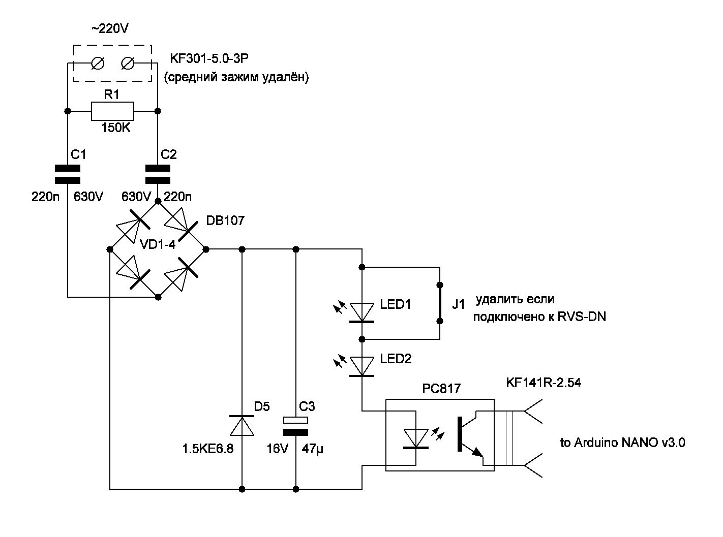
The boards contain three identical circuits, everything is placed in ABS plastic boxes, size 100x100 mm.
')
Photo optocoupler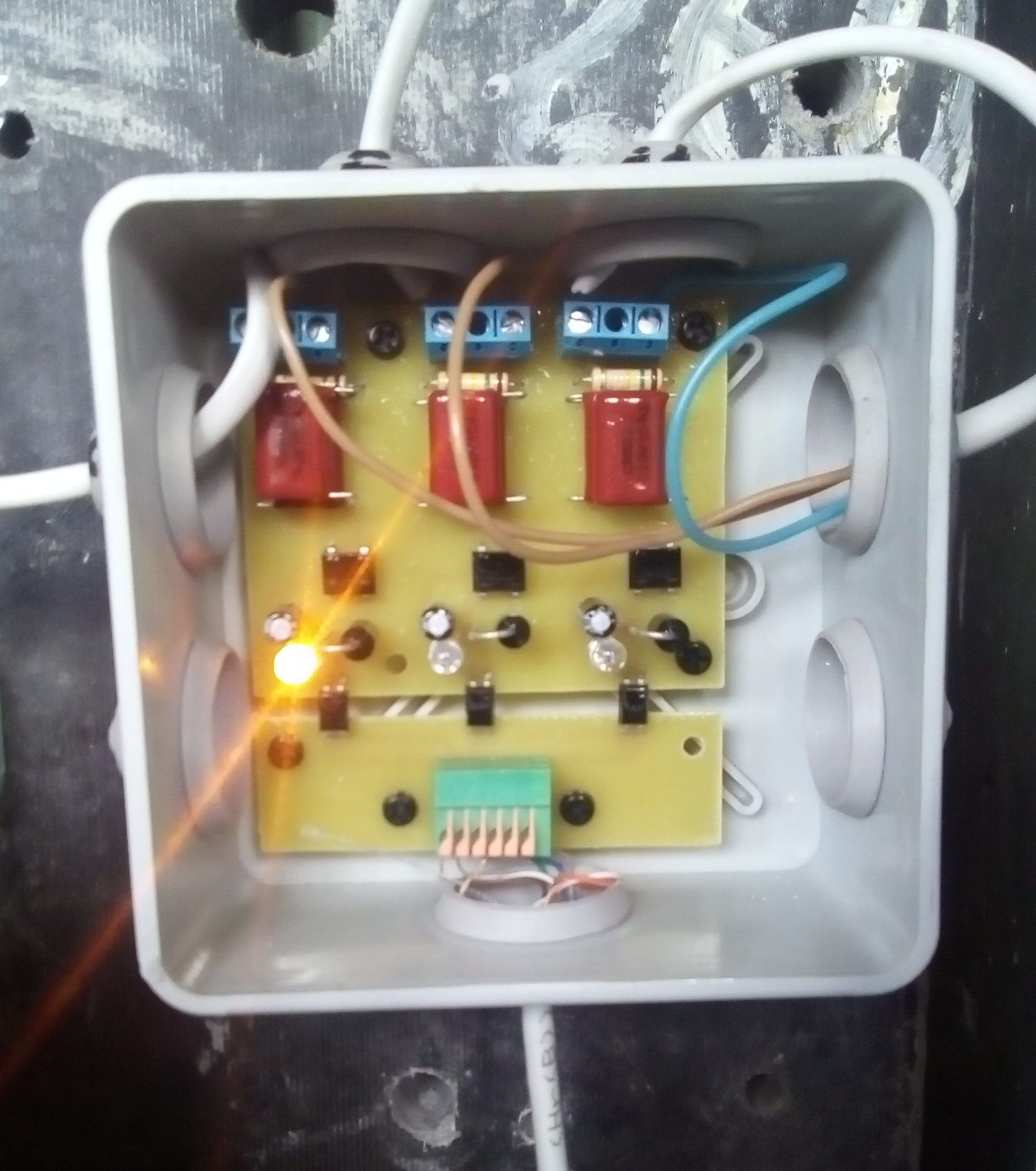
When connected to the starters with semiconductor valves, their leakage current is sufficient for opening the PC817 and there will be a false trigger. To avoid this situation one more is added in series to the optocoupler LED and the work indication LED. To do this, jumper J1 opens and solder the additional LED1.
The receiving part is made on
side 1
side 2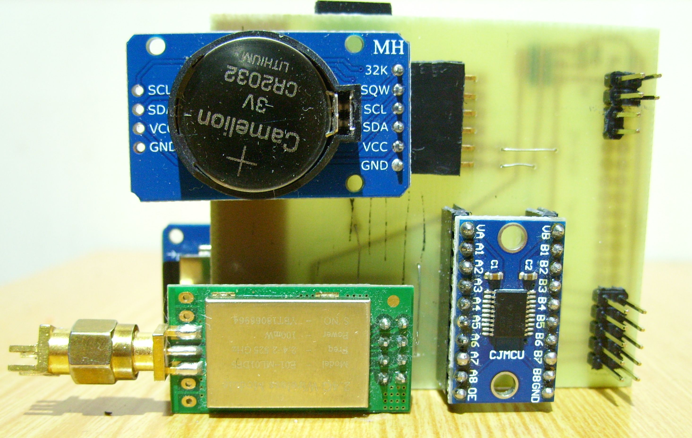
prototype board connected to ARDUINO MEGA 2560. For this purpose, a double-row connector is used on the end. A screen with a resolution of 240x400 is used as a display device.
HX8352B.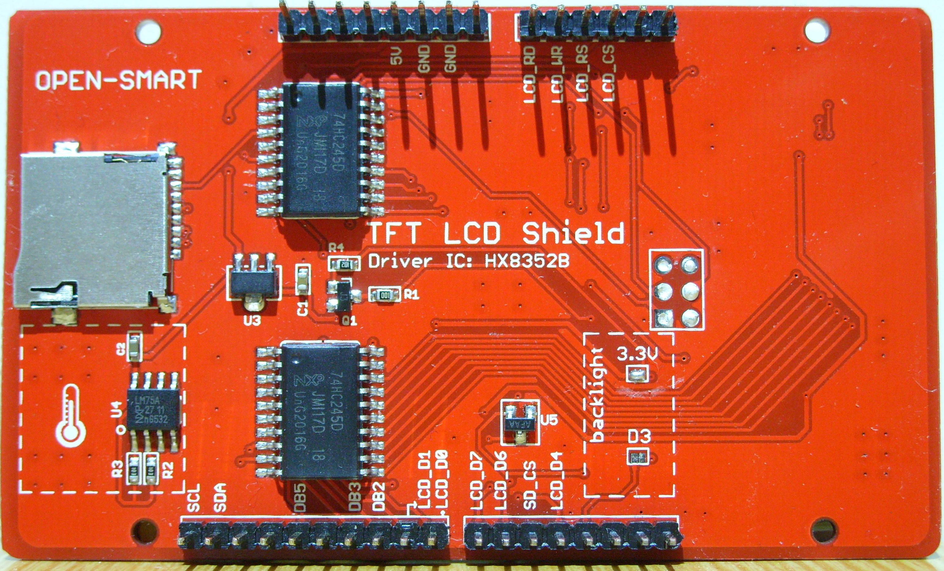
Moreover, the connector to the ICSP on the screen board is removed and the slot for micro SD is not used. The fact is that the “native” SD slot cannot be applied due to a conflict on the SPI bus. A separate card reader with a 3.3V stabilizer and a three-state buffer chip 74LVS125A was used for the flash card. Here a rake waited for me. A tri-state buffer, but it worked either as an E01-ML01DP5 or card reader. In the comments of the library SdFat saw a warning about incompatibility with other devices. The level converter on TXS0108E has been removed and replaced by jumpers, as E01-ML01DP5 tolerant to 5V signals, did not help. Using an oscilloscope, the signal was lost on the MISO line when the card reader was connected. On closer examination, it was found that the inputs of the enabling signals of the OE 4 channels 74LVS125A were simply soldered to the common wire and there could be no third state of speech. The buffer chip was used as a primitive level converter from 5V to 3.3V using 3.3 KΩ resistors connected in series with the signal lines. Besides the MISO line. Her bottom output key probably pulled the signals to ground level. Having determined that the resolving signal of the MISO line is pin 13, it was cut off from the track and
soldered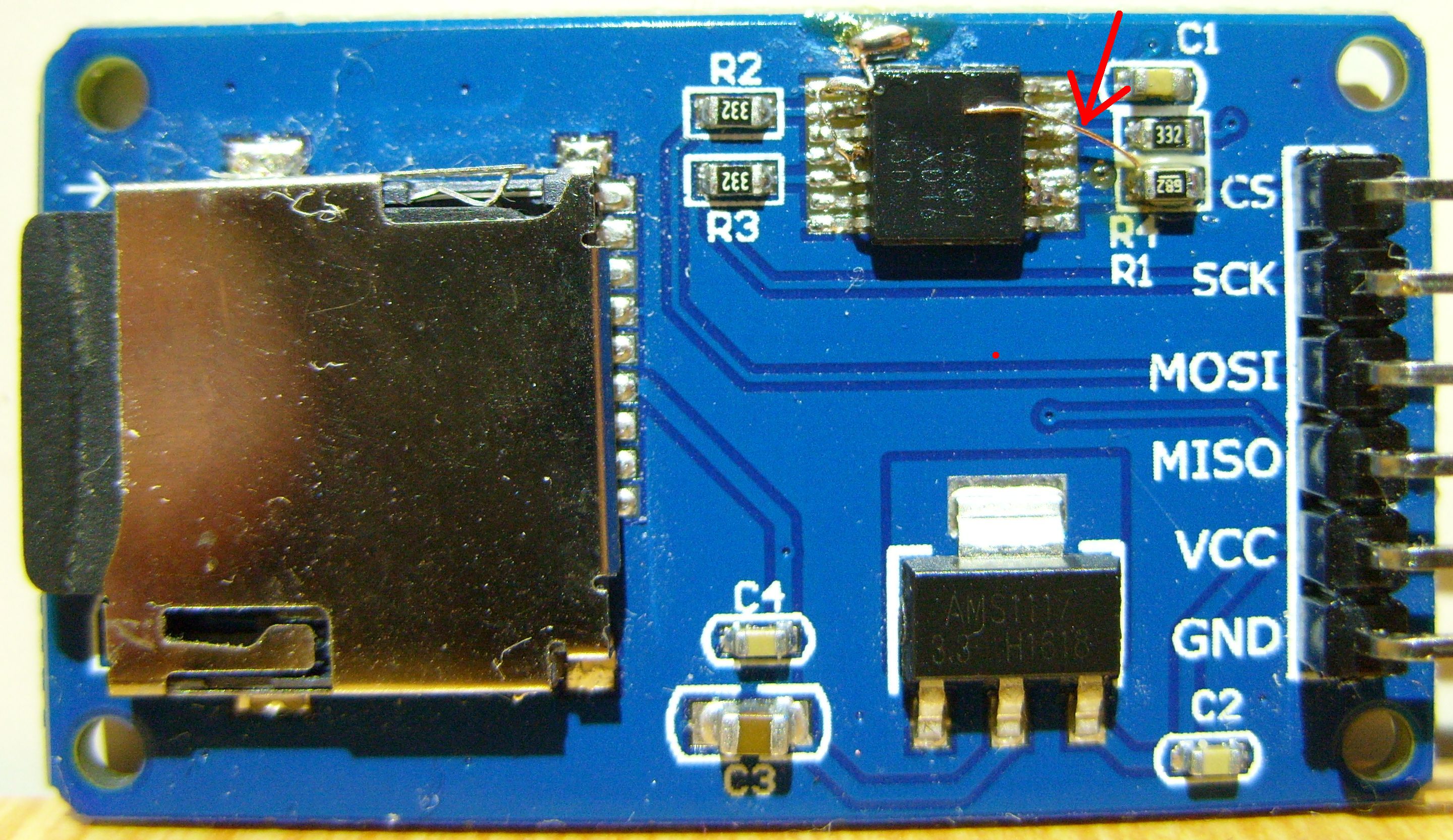
between the output of the input device selection (9) 74LVS125A CS and the matching resistor. Now, if there is no access to the memory card, the MISO buffer is disabled and does not interfere with the operation of another device.
Breadboard layout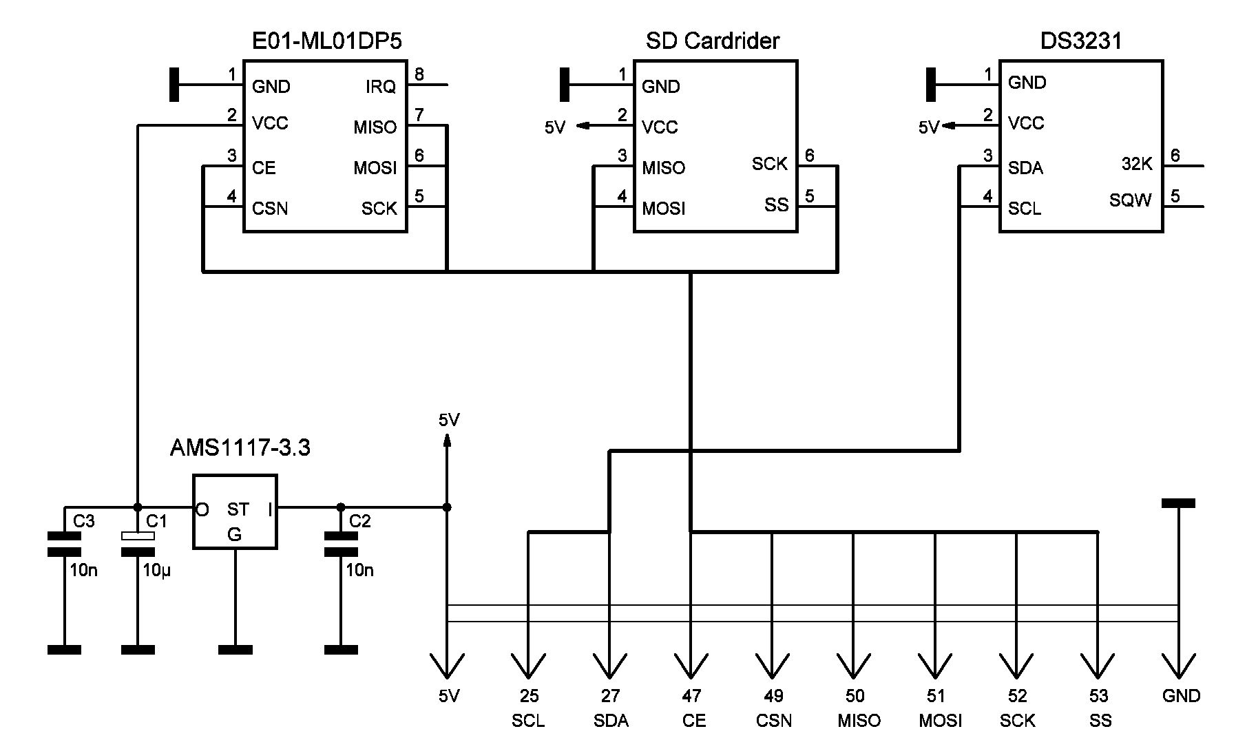
Receiver at work
To connect the clock on the DS3231, I2C (TWI) software bus is used.
Arduino IDE program
// IMPORTANT: Adafruit_TFTLCD LIBRARY MUST BE SPECIFICALLY // CONFIGURED FOR EITHER THE TFT SHIELD OR THE BREAKOUT BOARD. // SEE RELEVANT COMMENTS IN Adafruit_TFTLCD.h FOR SETUP. //by Open-Smart Team and Catalex Team //catalex_inc@163.com //Store: http://dx.com // https://open-smart.aliexpress.com/store/1199788 //Demo Function: Display graphics, characters //Arduino IDE: 1.6.5 // Board: Arduino UNO R3, Arduino Mega2560,Arduino Leonardo // Board:OPEN-SMART UNO R3 5V / 3.3V, Arduino UNO R3, Arduino Mega2560 //3.2INCH TFT: // https://www.aliexpress.com/store/product/3-2-TFT-LCD-Display-module-Touch-Screen-Shield-board-onboard-temperature-sensor-w-Touch-Pen/1199788_32755473754.html?spm=2114.12010615.0.0.bXDdc3 //OPEN-SMART UNO R3 5V / 3.3V: // https://www.aliexpress.com/store/product/OPEN-SMART-5V-3-3V-Compatible-UNO-R3-CH340G-ATMEGA328P-Development-Board-with-USB-Cable-for/1199788_32758607490.html?spm=2114.12010615.0.0.ckMTaN #include <Adafruit_GFX.h> // Core graphics library //#include <Adafruit_TFTLCD.h> // Hardware-specific library #include <MCUFRIEND_kbv.h> MCUFRIEND_kbv tft; #include "SdFat.h" // Use the SdFat library SdFat SD; SdFile file; File myFile; #define SD_CS_PIN SS #include <SPI.h> // SPI #include <nRF24L01.h> // RF24 #include <RF24.h> // nRF24L01+ RF24 radio(47, 49); #include <DS3231.h> DS3231 rtc(27, 25); Time t; uint16_t r = 6000; uint32_t k = 0; volatile unsigned long data; float leb_1; float leb_2; float leb_3; float leb_4; uint8_t pipe; int rc = 0; uint8_t time_sec_prev; uint8_t time_day_prev; //***********************************************// // If you use OPEN-SMART TFT breakout board // // Reconmmend you to add 5V-3.3V level converting circuit. // Of course you can use OPEN-SMART UNO Black version with 5V/3.3V power switch, // you just need switch to 3.3V. // The control pins for the LCD can be assigned to any digital or // analog pins...but we'll use the analog pins as this allows us to //----------------------------------------| // TFT Breakout -- Arduino UNO / Mega2560 / OPEN-SMART UNO Black // GND -- GND // 3V3 -- 3.3V // CS -- A3 // RS -- A2 // WR -- A1 // RD -- A0 // RST -- RESET // LED -- GND // DB0 -- 8 // DB1 -- 9 // DB2 -- 10 // DB3 -- 11 // DB4 -- 4 // DB5 -- 13 // DB6 -- 6 // DB7 -- 7 // Assign human-readable names to some common 16-bit color values: #define BLACK 0x0000 #define BLUE 0x001F #define RED 0xF800 #define GREEN 0x07E0 #define CYAN 0x07FF #define MAGENTA 0xF81F #define YELLOW 0xFFE0 #define WHITE 0xFFFF #define GRAY 0x8C51 #define GRAYD 0x39E7 //Adafruit_TFTLCD tft(LCD_CS, LCD_CD, LCD_WR, LCD_RD, LCD_RESET); // If using the shield, all control and data lines are fixed, and // a simpler declaration can optionally be used: // Adafruit_TFTLCD tft; uint16_t g_identifier; String dataString; //String numfileMonth ="1.txt"; char perv [] = {"2.txt"}; //String *numfileMonth="1.txt" (sizeof (numfileMonth)); /////////////////////////////////////////////////////////////////// void setup(void) { rtc.begin(); // - // rtc.setDOW(6); // // rtc.setTime(22, 04, 0); // , 24 . // rtc.setDate(4, 5, 2019); // , 29 2018. Serial.begin(2000000); //////// tft.begin(0x65); tft.reset(); tft.setRotation(0); tft.cp437(true); ////////////////// , , tft.fillScreen(BLACK); tft.setTextColor(WHITE); tft.setTextSize(2); tft.setCursor (8, 0); tft.println ("DEVELOPERS & BUILD" ); tft.setCursor (30, 20); tft.print (utf8rus(" .." )); tft.setCursor (40, 40); tft.print (utf8rus(" .." )); delay (2000); radio.begin(); // nRF24L01+ radio.setChannel(120); // ( 0 127) radio.setDataRate (RF24_250KBPS); // (RF24_250KBPS, RF24_1MBPS, RF24_2MBPS), RF24_1MBPS - 1/ radio.setPALevel (RF24_PA_MAX); // (RF24_PA_MIN=-18dBm, RF24_PA_LOW=-12dBm, RF24_PA_HIGH=-6dBm, RF24_PA_MAX=0dBm) radio.openReadingPipe (1, 0xAABBCCDD11LL); // 1 1 0xAABBCCDD11, // 2 2 0xAABBCCDD22, radio.startListening (); // , // radio.stopListening (); //////// tft.fillScreen(BLACK); tft.setCursor (8, 0); tft.setTextSize(1); //////// SD Serial.println("Initial SD card"); tft.println("Initial SD card"); tft.setCursor (8, 10); //////// if (!SD.begin(SD_CS_PIN)) { Serial.println("initial failed!"); tft.fillRect ( 8 , 10 , 85 , 7 , RED); tft.setTextColor(BLACK); tft.println("Initial failed!"); return; } tft.setTextColor(WHITE); Serial.println("initialization done"); tft.println("Initialization done"); delay (2000); //////// - t = rtc.getTime(); time_sec_prev = t.sec; time_day_prev = t.date; //////// , tft.setCursor ( 180 , 0 ); // tft.fillRect ( 178 , 0 , 65 , 7 , GRAY); // tft.setTextSize(1); tft.print(rtc.getDateStr()); //////// tft.setTextSize(2); tft.setCursor (60, 25); tft.println (utf8rus(" I")); //////// tft.setTextSize(1); tft.setCursor(130, 10); // 2.txt , if (SD.exists (perv)) { //tft.setCursor(0, 90); tft.println(perv); Serial.println(perv); } else { myFile = SD.open(perv, FILE_WRITE); // 2.txt , myFile.close(); tft.println(perv); Serial.println(perv); } } void loop(void) { //////// - if (Serial.available() > 0) { //////// , File myFile = SD.open(perv); // if the file is available, write to it: if (myFile) { while (myFile.available()) { Serial.write(myFile.read()); } myFile.close(); } else { Serial.println("error opening .txt"); } } //////// t = rtc.getTime(); tft.setTextColor(WHITE); //////// , if ( time_sec_prev != t.sec) { tft.setCursor ( 120 , 0 ); // tft.fillRect ( 118 , 0 , 50 , 7 , GRAY); // tft.setTextSize(1); tft.print(rtc.getTimeStr()); // time_sec_prev = t.sec; } //////// , if ( time_day_prev != t.date) { tft.setCursor ( 180 , 0 ); // tft.fillRect ( 178 , 0 , 65 , 7 , GRAY); // tft.setTextSize(1); tft.print(rtc.getDateStr()); // time_day_prev = t.date; } //////// , if (radio.available(&pipe)) { //////// , radio.read(&data, sizeof(data)); //////// , if (pipe == 1) { //////// // if ( data == 0000 ) { rc = 0; } else { rc ++; } //////// 10 100- if ( rc == 1 ) { leb_1 = data / 3600.0; } if ( rc == 2 ) { leb_2 = data / 3600.0; } if ( rc == 3 ) { leb_3 = data / 3600.0; } if ( rc == 4 ) { leb_4 = data / 3600.0; } } } r ++; k ++; // //////// if ( r >= 6500) { tft.setTextSize(2); tft.fillRect ( 0 , 41 , 180 , 64 , GRAYD); Serial.println ("Lebedki I"); tft.setCursor (0, 41); tft.println (leb_1); Serial.println (leb_1); tft.println (leb_2); Serial.println (leb_2); tft.println (leb_3); Serial.println (leb_3); tft.println (leb_4); Serial.println (leb_4); Serial.println (k); r = 0; } //////// SD 10 . if ((t.min % 10 == 0) && ( t.sec == 0)) { tft.setTextSize(1); tft.setCursor(200, 10); tft.setTextColor(BLACK); //////// .csv String dataString = String (rtc.getDateStr()) + ", "+(rtc.getTimeStr()) + ", " + (leb_1) + ", " + (leb_2) + ", " + (leb_3) + ", " + (leb_4) + ", "; //////// myFile = SD.open(perv, FILE_WRITE); // "2.txt" - , . if (myFile) { myFile.println(dataString); myFile.close(); tft.fillRect ( 198 , 8 , 42 , 10 , GREEN); tft.println("SD OK"); Serial.println("SD OK"); delay (900); // , 13 , } else { tft.fillRect ( 198 , 8 , 42 , 10 , RED); tft.println("SD ERR"); Serial.println("SD ERR"); } } } Character conversion program
/* Recode russian fonts from UTF-8 to Windows-1251 */ String utf8rus(String source) { int i,k; String target; unsigned char n; char m[2] = { '0', '\0' }; k = source.length(); i = 0; while (i < k) { n = source[i]; i++; if (n >= 0xC0) { switch (n) { case 0xD0: { n = source[i]; i++; if (n == 0x81) { n = 0xA8; break; } if (n >= 0x90 && n <= 0xBF) n = n + 0x30;//0x2F break; } case 0xD1: { n = source[i]; i++; if (n == 0x91) { n = 0xB8; break; } if (n >= 0x80 && n <= 0x8F) n = n + 0x70;//0x6F break; } } } m[0] = n; target = target + String(m); } return target; } The program for recoding characters for Cyrillic output by the Adafruit_GFX library is placed in the same folder as the main program. It is also necessary in Adafruit_GFX to replace the file glcdfont.c with a different font. Here is the library with the required replacement. More information about the Russification is easily searched on the Internet.
Summing up, I will say that the system has met expectations, it has become easier to follow the equipment. Although everything is collected on the mockups, and there are no urgent complaints about the work.
The first elements have been working for more than six months and have survived the winter. The latest design for 9 controlled units has been operating since March 5, and it is officially recording the operating time.
Source: https://habr.com/ru/post/451154/
All Articles