Resistor in the gate circuit or how to do it right
Good day to all!
This small article may become a cheat sheet for novice developers who want to design reliable and efficient control circuits for power semiconductor keys, update and refresh the old knowledge of experienced specialists, or can at least scratch the memory bins of readers somewhere.
')
Any of these cases I will be very happy.
In this post I will try to describe the most common issues of choosing the gate resistors for power electronic devices. It is based on knowledge drawn from various literature, apnotes from TOSHIBA, Infineon, Texas Instruments and also from modest practice. It is worth noting that this information does not give directly universal recommendations for each power switch. However, it is possible to analyze what assumptions may be important and what effect they may have on the choice of gate resistors for discrete power transistors, as well as for power modules.
The basics
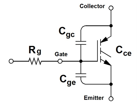
The gate resistor is located in the circuit between the driver of the power transistor and the gate of the transistor itself, as shown in the image in the header of the article.
Opened or closed field key (IGBT / MOSFET) depends on the voltage applied to the gate. A change in this voltage charges or discharges the stopper capacitances of the power device, which consist of the capacities of the gate manifold and gate emitter and a small capacity of the shutter. The charge on the input capacitance of the key will turn it on (current ), and the discharge will turn off (current ).
The resistor in this circuit limits the charge / discharge current of the input capacitances; in addition, a properly selected resistor will not allow the key to open spontaneously, which sometimes can happen, due to the rapid change in voltage on the power outputs of the key, for example, this can happen when the neighboring the key opens. In this case, the capacity recharges and the current flowing through the gate resistor causes a voltage drop across it, which can open the key. In addition, the threshold for opening a key is often greatly lowered as the temperature of a semiconductor crystal rises.
What you need to know and how to choose the “right” resistor
1. Maximum charge / discharge current output driver
Any driver chip has such a parameter as the maximum output current. If the gate current when the key is opened / closed exceeds the value of the maximum output current, then the driver may fail, therefore, in this case, the gate resistor will limit the output current of the driver.
You can make an equivalent circuit model, by which you calculate the required value of the resistor:

Following simple conclusions, we can get formulas for calculating the driver current, and choose a gate resistor so as not to exceed the maximum permissible driver parameters:
2. Dissipated power
Also one of the important functions of the gate resistor is to dissipate the power of the output stage of the driver chip. In accordance with the model above, the power dissipation can be calculated using the following formulas:
Here - charge the shutter key, and - switching frequency.
After calculating and selecting a resistor, it is important to observe the following condition:
Where - own driver consumption.
There is still a small note, in most datasheets the keys indicate the gate charge under certain conditions, for example, when the gate control voltage is + 15V ... -15V, if there is another control voltage in your circuit, for example + 15V ... 0V, or +15 ... -8V, then the following relations will help to determine the shutter charge accurately enough:
3. Turn-on speed and electromagnetic compatibility
Let's consider switching losses as a function of the resistance of the gate resistor. I'll take the key that I recently used in my small project - IKW40N120 from my favorite Infineon:

As you can see, as the shutter resistance increases, the switching speed decreases and the switching loss increases. Accordingly, this will affect the effectiveness of the system as a whole. On the contrary, if a smaller gate resistance is used, switching will become faster and losses will decrease, but the noise caused by a rapid increase in current and voltage will increase, which can be critical when you need to meet the requirements of electromagnetic compatibility, therefore the gate resistance value must be chosen very carefully .
4. That same “parasitic” inclusion
In the beginning, when I wrote about the functions of the gate resistor, I mentioned the possibility of a key to spontaneously turn on. To avoid this, you can calculate the voltage that may appear on the gate of the transistor, look at the image below and write down two small formulas:

And do not forget that the voltage of opening the key is strongly dependent on the temperature of the crystal, and this also needs to be taken into account.
Conclusion
Now we have the formulas for optimal (to some extent) selection of such a simple element of a power circuit as a gate resistor at a glance.
It is quite possible that you did not find anything new here, but I hope that at least this note will be useful to someone.
Also, to broaden my horizons, including in the area of power key management, I strongly advise you to set aside an hour or two a week to read all sorts of articles and apnotes from eminent manufacturers of power electronics, in particular about the use of driver chips. I am sure you will find a lot of interesting things there. For a start, and to dive into the topic under discussion, I propose this one .
Thanks for reading!
Source: https://habr.com/ru/post/451152/
All Articles