Object Oriented Programming in Graphic Languages
Object-oriented programming (OOP) is a concept that is designed to facilitate the development of complex systems by introducing new concepts that are more close to the real world than functional and procedural programming languages. As Wikipedia writes, “An ordinary human language as a whole reflects the OOP ideology, starting with the encapsulation of a subject as its name and ending with the polymorphism of using a word in a figurative sense, which ultimately develops the expression of a representation through the name of the object to a full-fledged concept - class.

But from the point of view of all those who first encountered these abstractions, after classical procedural languages did not become clearer, it seems the opposite is still more confused.
On the other hand, there are graphic notations of the program's work, which are not close to the human language, but much clearer than even any code, not like OOP. It is possible that this is more understandable to me, spoiled by engineering education, but there are a lot of people like me and this text is for the same spoiled physicists who do not understand high abstractions.
Here, for example, is the real description in graphic notation of the algorithm for controlling NPP valves:

Figure 1. An example of a nuclear power plant management program in graphic notation
On the left are input signals, on the right are commands.
It seems to me that even a child can read such an algorithm:
')
- If the pump is turned on for 60 seconds and the flow rate is less than 10, then open the valve for recycling.
- If the pump is turned on, then open the valves 001 and 002 within 5 seconds to open the command.
- If the flow is greater than 20 and the pump is turned on, then within 5 seconds, the valve 003 must be commanded to close.
When I was a student, I was working part time by creating a component library for Delphi and was familiar with first-hand PLO. Then, when confronted with real NPP control programs, I was very surprised that there was no abstraction, encapsulation and, God forgive me polymorphism, only pure C, and it is also advisable to be cut down by the rules and MISRA C recommendation, so that everything is reliable , portable, safe.
The climax of C cutting in my practice was the FIL language, for RBMK reactor control systems. In it, functions were written in advance in C, compiled, and then called based on a text file, where they were described in the FIL language. As a result, it was possible to call only a limited, but carefully checked and debugged set of functions. And all this - in the name of safety and reliability.
But at the same time, the reactor control system and the NPP control system as a whole is just the case where the principles of the PLO should be applied in full growth. In fact, there are a lot of equipment of the same type - valves, pumps, sensors, everything is easily classified, there are ready-made objects corresponding to the real equipment. It would seem, here it is - apply OOP, classes, inheritance, abstraction and polymorphism. But no, you need pure C and this is a security requirement.
And then - even more interesting. In fact, the program for managing NPPs is not written by a programmer, but by a technologist - only he knows what and when to close, open, turn on, and most importantly, he knows when to turn off all this canoe so that it does not go off. A programmer must neatly implement all this on C code. It is even better that the programmer would not exist at all, and the technologist himself would draw the technological algorithms of the control programs in graphical form, automatically generate the C code and load it into the control equipment. This is recommended by international safety standards, in which case the programmer, like a violinist, is not needed. It only introduces additional errors and distortions into the implementation of the technologist’s thoughts.

What was my amazement when I learned that NPP technologists and designers themselves, independently of the programmers, developed and successfully applied object-oriented programming, and even in graphic notations, but the resulting code fully satisfies the security requirements and does not contain OEF methodology artifacts .
In fact, if you look at the code that is generated from the circuit in Figure 1, you will see pure C without any classes there.
For example, the entry table in the algorithm:
/* Index=0 UID=0 GeneratorClassName=TSignalReader Name=KBA__AA.KBA31EY001.alg_inp Type= */ state_vars->kbaalgsv0_out_1_ = kba31ap001_xb01; state_vars->kbaalgsv0_out_4_ = kba31cf001_xq01; Just assigning variables.
Any block is described as a calculation of the output by input, taking into account the parameters specified in the list of constants. For example, the “More” block looks like this in the code:
/* Index=5 UID=5 GeneratorClassName=TLogBlock Name=KBA__AA.KBA31EY001.smu.GT2 Type= */ locals->v5_out_0_ = state_vars->kbaalgsv0_out_4_ > consts->kbaalgsv3_a_; The block output is the result of comparing the input signal with a value in a constant.
Thus, in other blocks, the local variables from the input variables are sequentially computed, and at the end of the program loop the output variables are written.
/* Index=14 UID=14 GeneratorClassName=TSignalWriter Name=KBA__AA.KBA31EY001.alg_out Type= */ if((action==f_InitState)||(action==f_GoodStep)||(action==f_RestoreOuts)){ kba31ey001_yb01 = locals->v8_out_0_; kba31ey001_yb11 = state_vars->kbaalgsv9_out_0_; kba31ey001_yb12 = state_vars->kbaalgsv12_out_0_; kba31ey001_yb02 = locals->v13_out_0_; }; And where are the classes, you ask?
The whole methodology related to OOP is in the variable names. It would seem that this could be in the name of a variable? And there may be a whole abyss. For example, the variable name is kba31ap001_xb01, just a variable in C code that meets the requirement for naming variables. However, for the designer’s technologist, it looks like this: “Reactor compartment, industrial water supply system, first pump, start-up”. All this transformation takes place thanks to the wonderful German coding system (Kraftwerk-Kennzeichensystem) KKS, quote:
“This coding classification system is designed for power plants and has great potential, and also takes into account the features of free-programmable microprocessor hardware.
Along with the marking of process equipment, executive bodies (shut-off and control, safety, shut-off, etc. valves, mechanisms of their own needs), measurement points, installation units, automation devices, buildings and structures, the KKS system allows you to label algorithms and programs of various types and assignments (algorithms for processing the measured technological parameters, signaling, automatic control, technological protection, logic control: interlocks, ATS, step-by-step programs, - calculating t hniko-economic indicators and diagnostics of process equipment status) input, output and intermediate signals of algorithms and programs, video recordings of all levels are displayed on video terminals, cables, etc. ".
But the most interesting thing in the last part of the name is _xb01 , what is given through the underscore character. If you look at the signal base for the project management, we will see classes there that are clear and familiar to everyone who once, somehow and somewhere was interested in the PLO (see Fig. 2).
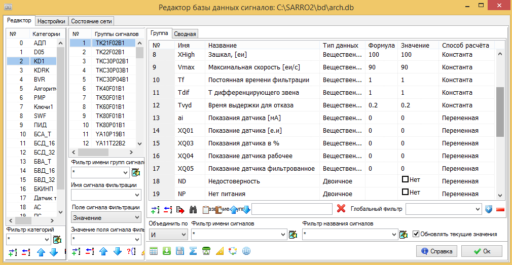
Figure 2. An example of the structure of the base signals for the control system of nuclear power plants.
We have classes, or tables, in the picture is the "Categories" column. For example, “KD1” which have a table of pattern signals, class fields Upper measurement limit, lower measurement limit, sensor reading , etc. - this is an abstraction.
And there is also the implementation of this class - a specific sensor, for example TK21F02B1, located in the circuit, as you already guessed from its name, in the “Reactor compartment, industrial water supply system, at the first pump”, and that it is a flow sensor, too There is in this title, but this is not accurate.
And this instance of this class has specific signals and their values in the course of the program, and they can be accessed by the class field names. For example, the sensor reading is indicated by the variable TK21F02B1_XQ04.
At this point, you can say, wait, this is not exactly the PLO, or even not at all the PLO, there is just a data structure, it is in standard C as well. And where is the encapsulation of methods in the class? Data processing should be in class, then this will be a real kosher OOP method.
Let's see how the subroutine of monitoring the reliability of the sensor looks like in graphical form. In Figure 3, part of the signal processing circuit:
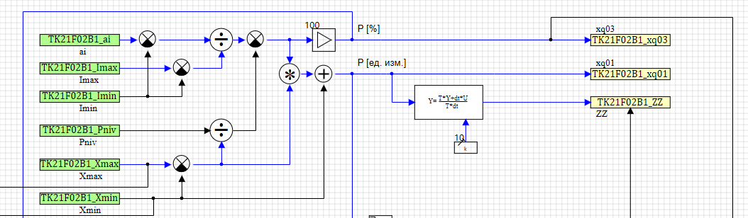
Figure 3. An example signal processing program.
It can be seen that in the processing subroutine the names of the variables TK21F02B1_XQ04 are used, formed according to the rules KKS and on the basis of the table of class fields. In the above example, the sensor readings are calculated as a percentage of TK21F02B1_XQ03 using the specified values of the fields of the class instance, such as TK21F02B1_Xmin and TK21F02B1_Xmax.
If we turn to the code generated from this scheme, we will see a simple assignment of the value to a variable, pure C and no pluses and OOP.
/* Index=12 UID=12 GeneratorClassName=TSignalReader Name=KD1.kd3_45.SR6 Type= */ state_vars->su100v12_out_0_ = tk21f02b1_ai; And the assignment of the result of the calculation, also as a simple assignment of a variable (with a validation of the number, so as not to drop the system if we received an error as a result of signal processing)
/* Index=100 UID=100 GeneratorClassName=TSignalWriter Name=KD1.kd3_45.SW3 Type= */ if(isfinite(locals->v63_out_0_)){ tk21f02b1_xq04 = locals->v63_out_0_; }; And at what point does the combination of data fields of the processing method class appear? In fact, I am familiar with two variants of this focus. Now we analyze one of them.
Let's see how the block is configured in the diagram in which the circuit of the processing program is located (see Fig. 4).
We have a scheme on which we place blocks of a submodel of a graphical programming language, inside these blocks there is a graphic scheme, part of which is shown in Figure 3, - a program for processing signals from sensors.
In the properties of this block, we see the fields of the signal database and the drop-down list containing the signals already existing in the database, class instances, and specific sensors of this type. Simply select the desired sensor, a copy of the class by name and a miracle happens. In the scheme, all reading and writing blocks receive names of the type TK21F02B1_XQ03 , (sensor name of the class instance + field name).
Now when generating the C code, all variables will receive the values of the desired sensor. And the programmer is not needed, the technologist did everything himself when he developed a scheme in a graphical programming language for the NPP control algorithm.
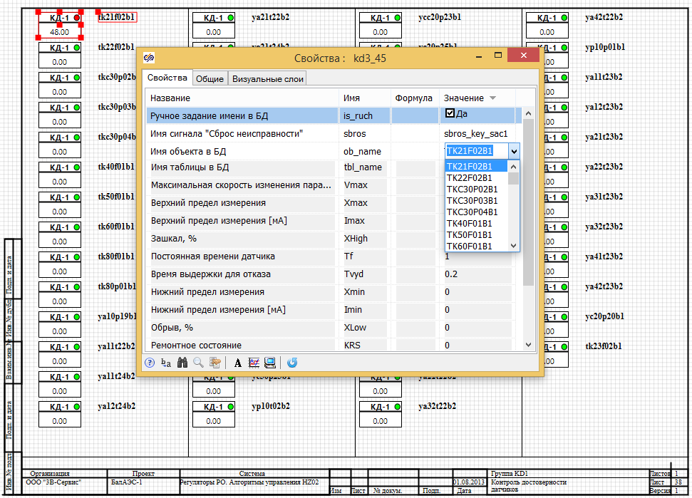
Figure 4. Example of setting the processing circuit of the sensor.
For assignment of names, a special automation script in the design environment of control systems is used, approximately the same as in Figure 5. All reading blocks on the diagram are assigned names consisting of the object name and the field name in the class (see Fig. 5).
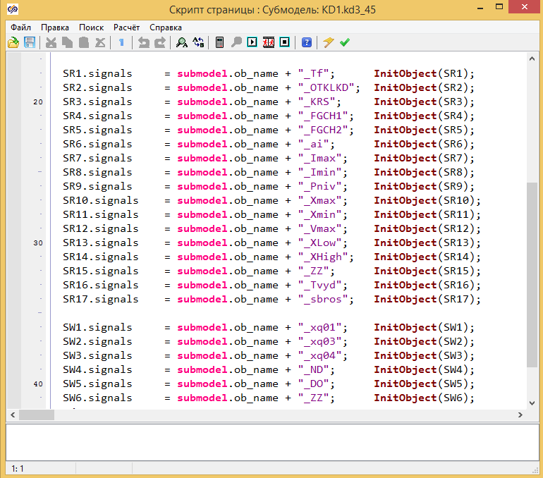
Figure 5. Setting variable names in read blocks.
It is clear that in an analogous way an unlimited number of signal processing options can be created, in fact methods for a class in OOP methodology. Similarly, they can be formed for a sensor, its summing up when displayed on a SCADA system video frames, or, for example, the processing of settings change procedures. The scheme is created graphically, saved as a block and used when necessary.
To summarize: in graphical programming languages, OOP methods are also used and are beneficial. And after the generation of the source code of control programs, all the artifacts of the OOP methodology disappear and remain, pure C, safe, reliable, verifiable.
It is clear that such an application of automation tools, in addition to speeding up the development, also makes it possible to significantly reduce development time and the number of errors in control programs.
Source: https://habr.com/ru/post/451148/
All Articles