Sound alarm
Sound alarm
This article is about creating an alarm. The project will consist of several parts, one of which is responsible for sound, the other for triggering an alarm, and the third for packing the device into the case.
- Miniature drill, for example, proxxon lu-6868.
- Soldering iron, solder, flux.
- Tester and crocodile clips to it.
- Development board for soldering with leads.
- Solderless prototyping board.
- Plastic case for the product.
- F4 plugs, power port.
- Battery 9-12 volts or power supply of the same rating.
- 1 red, 1 yellow LED, one 1N4001 diode.
- Speaker 8th.
- Relay 2 groups of switches (DPDT), 8 contacts, 5 volts DC tripping.
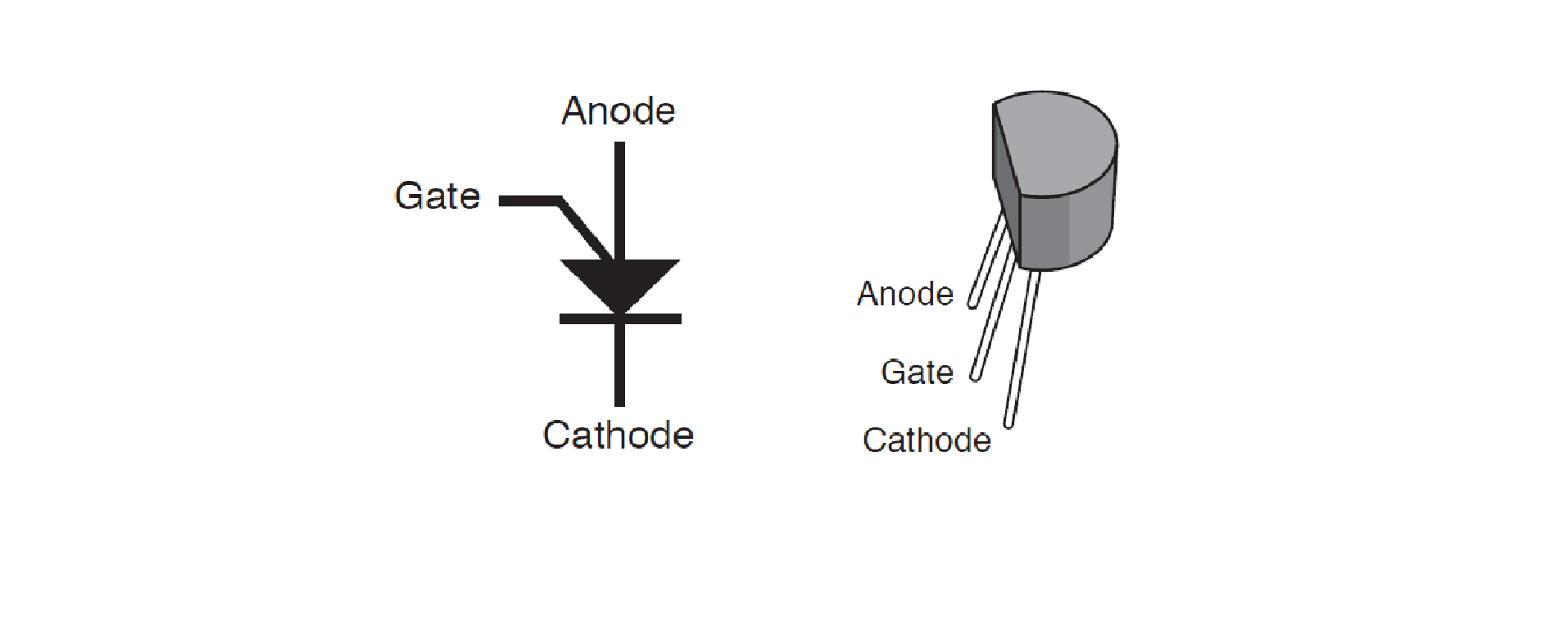
- 2N6027 programmable transistor. Number 2
- Resistors, of different ratings, power 0. 250W.
- Electrolytic capacitors of different ratings.
- Ceramic capacitors of different ratings:
- Jumpers - set.
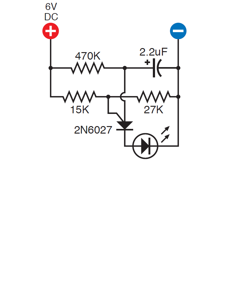
In order to understand how a single junction transistor works, assemble a circuit on a breadboard.
Click to enlarge.
Click to enlarge.
The LED will blink.
')
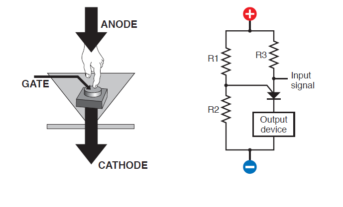
When a certain voltage level is reached, the transistor transmits current. If the voltage level drops, the transistor closes. The voltage level is regulated by the gate.
Click to enlarge.

Click to enlarge.
In the previously assembled circuit, the 15 kΩ and 27 kΩ resistors regulate the voltage on the Gate. The 470 kΩ resistor takes over most of the voltage and therefore the transistor remains closed. The capacitor starts charging, and at the same time the voltage between the anode and the cathode of the transistor increases. Then the transistor opens (the LED illuminates) and the capacitor starts to discharge until the voltage drops and the transistor closes. (The LED goes out). And so in a circle.
In the following diagram, add a less capacitive capacitor. As is known according to the rule of the RC circuit, the smaller the capacitor capacity, the slower it charges. Waveform voltage drop on a programmable transistor is shown above.
The human ear can catch a large frequency of discharge-charge cycles, so we will add a different speaker circuit.

Click to enlarge.
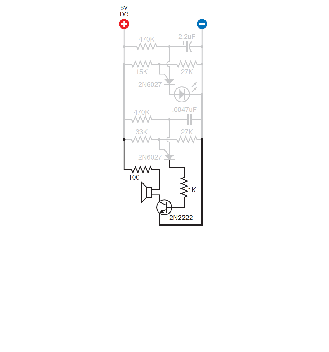
Putting your ear to the speaker, you will hear a quiet squeak. To amplify the signal, you can add a transistor to the circuit. As you know the transistor amplifies the current passing through the base.
Click to enlarge.
Add another transistor.
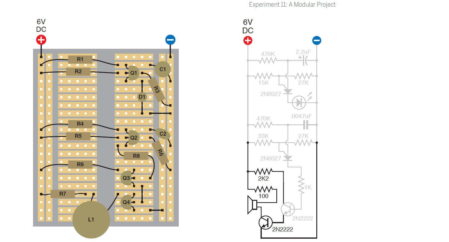
Click to enlarge.
Now audibility has improved significantly.
In order to make the sound look like an alarm, you need to connect the cathode of the first programmable transistor to the Gate of the second transistor. Its oscillations on the Gate will change the voltage of the second transistor's pass dynamically, creating a sound from two tones. It is also necessary to add a resistor and a capacitor in order to smooth the signal.
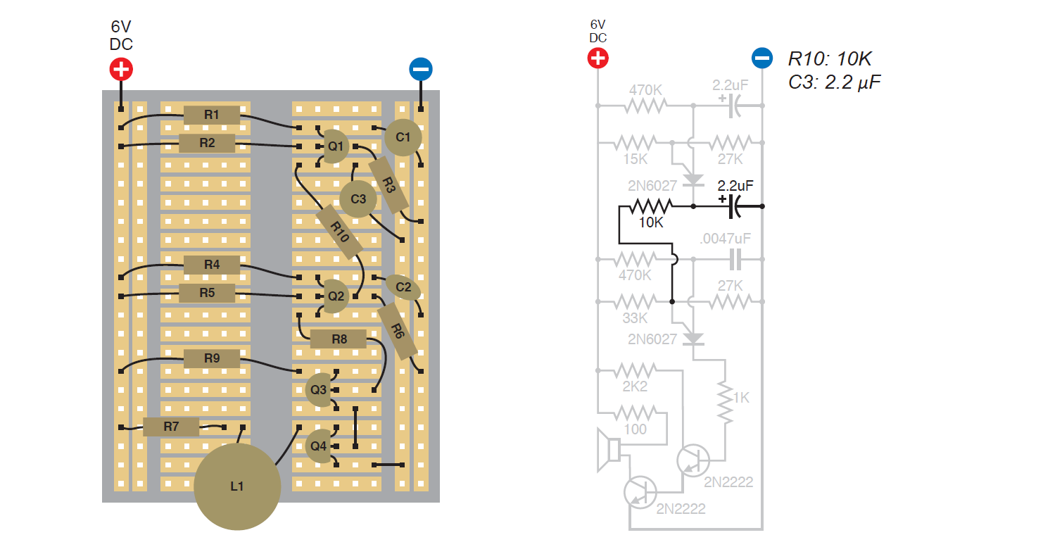
Click to enlarge.
The alarm pattern is shown below.

Click to enlarge.
The device is activated by magnetic sensors.
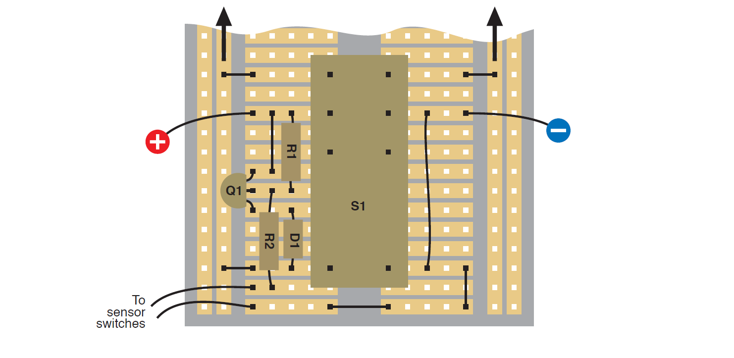
Click to enlarge.
Transfer the entire circuit to the solder board with leads and create a product.

Click to enlarge.
If everything works correctly, in a body mounted installation, assemble the following diagram.
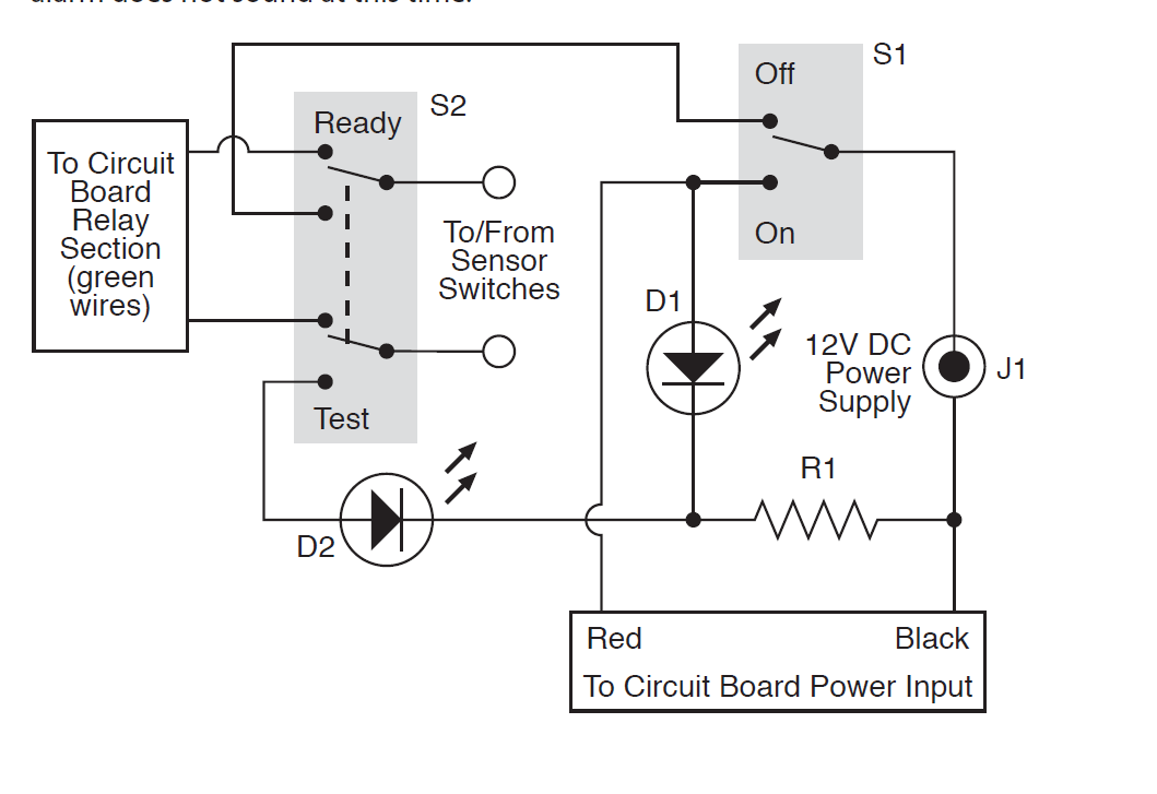
Click to enlarge.
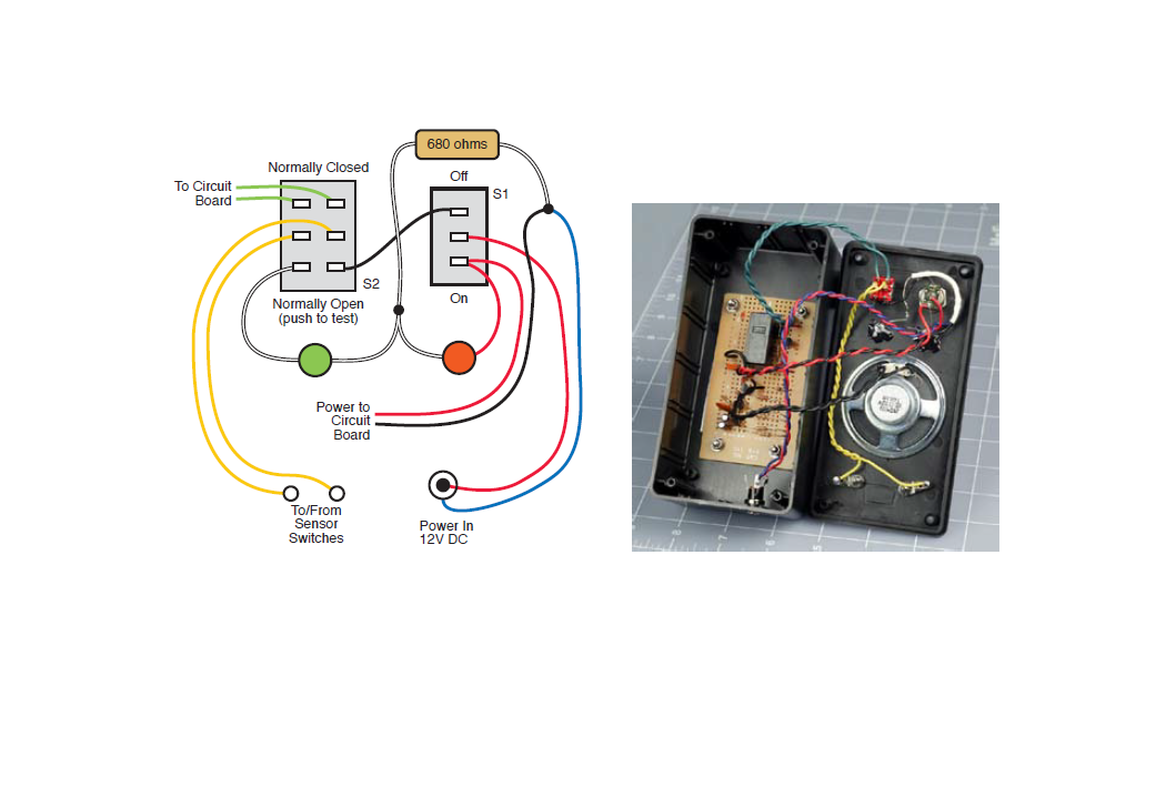
Click to enlarge.
When the button is pressed when the switch is on, the green LED will be lit when the sensors are connected. When the switch is in the “on” position, the red LED will be lit. When the switches open, an alarm will be triggered. It also works by pressing a button. The final result is in the video with my cat Masha.
Source: https://habr.com/ru/post/451110/
All Articles