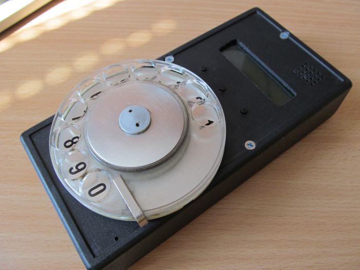
Cell phone dial on LPC810
Of course, this is “porridge from the ax”, because besides the LPC810 with its six GPIO, we also need a GSM module. For the basis of the firmware taken examples from here , the firmware itself is here .
To connect the four contact groups (three buttons and a dialer), as well as the display on the HD44780, operating in four-bit mode, the following scheme is applied to the three pins of the microcontroller:
')
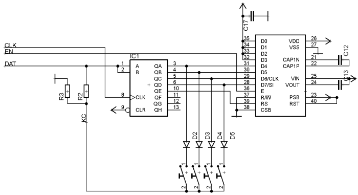
Shift register - type 74HC164. To poll one of the contact groups, you need to write the number 0x01, 0x02, 0x04 or 0x08. The display module "does not pay attention" to what is happening, since there is zero on the EN line, and the signal about the state of the selected contact group is fed to the DAT line.
The resistors are chosen so that the signal from the microcontroller takes precedence over the signal from the contact group, namely, R2 - a few kΩ, R3 (pull-down) - 22 kΩ.
The STATUS signal from the GSM module controls the voltage regulator. If you turn on the module, voltage will appear on this line, and the entire device will turn on. When you manually or automatically turn off the GSM module, the entire device also turns off. Full scheme:
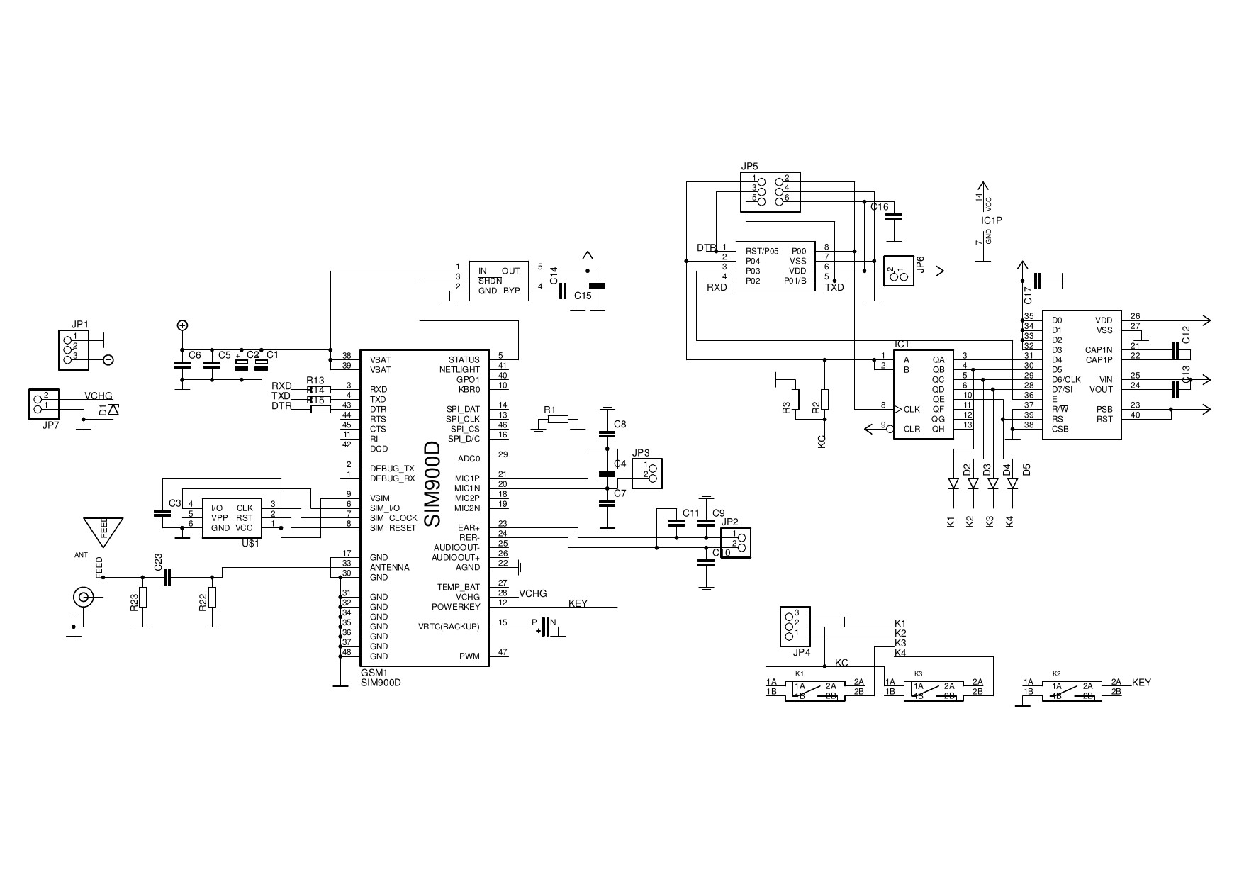
The same scheme in PDF
The firmware consists of two state machines. The first handles interrupts from the receiving UART line, writes the characters coming from there to the buffer, and when detecting AT sequences sets the appropriate flags. Another state machine is the main event loop, which reads these flags and changes its behavior depending on their state. The cycle takes about 16 ms, and this is enough for reading all digital inputs, including the input from the dialer.
The case is chosen large enough to fit the dialer, 1000 mAh battery, and everything else. There is enough space in the ROM so that in the future it was possible to implement the DTR line management, the transition to the energy saving mode and the caller ID.
Many pictures , files in Eagle 6 format , firmware sources
Source: https://habr.com/ru/post/450946/
All Articles