Intro Newton Protocol: what can fit in 4 kilobytes
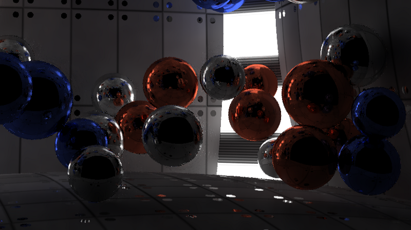
Recently, I participated in the Revision 2019 demostsen competition in the PC 4k intro category, and my intro won first place. I did coding and graphics, and dixan composed music. The main rule of the competition is to create an executable file or website that is only 4096 bytes in size. This means that everything has to be generated using mathematics and algorithms; in no other way will it be possible to squeeze images, video and audio into such a tiny amount of memory. In this article I will talk about the pipeline rendering of their intro Newton Protocol. Below you can see the finished result, or click here to see how it looked live on Revision, or go to pouet to comment and download the intro that participated in the contest. About the work of competitors and corrections can be found here .
Very popular in the 4k intro discipline is the Ray marching distance fields technique, because it allows you to set complex shapes in just a few lines of code. However, the disadvantage of this approach is the speed of implementation. To render a scene, you need to find the point of intersection of the rays with the scene, first determine what you see, for example, the beam from the camera, and then the subsequent rays from the object to the light sources to calculate the lighting. When working with ray marching, these intersections cannot be found in one step, you need to take many small steps along the beam and evaluate all objects at each point. On the other hand, when using ray tracing, you can find the exact intersection by checking each object only once, but the set of shapes that can be used is very limited: to calculate the intersection with the ray, you need to have a formula for each type.
In this intro, I wanted to simulate very accurate lighting. Since for this it was necessary to reflect millions of rays in the scene, in order to achieve such an effect, ray tracing seemed like a logical choice. I confined myself to a single figure — a sphere, because the intersection of the ray and the sphere is calculated quite simply. Even the walls in the intro are actually very large areas. In addition, it simplified the physics simulation; it was enough to take into account only collisions between spheres.
')
To illustrate the amount of code that fits in 4096 bytes, below I presented the full source code of the finished intro. All parts, with the exception of HTML at the end, are encoded as a PNG image in order to compress them into a smaller volume. Without this compression, the code would occupy almost 8900 bytes. The part called Synth is a trimmed version of the SoundBox . I used the Google Closure Compiler and Shader Minifier to package the code in this minimized format. In the end, almost everything is compressed into PNG using JsExe . The full compilation pipeline can be viewed in the source code of my previous 4k intro Core Critical , because it completely coincides with the one presented here.

Music and synthesizer are fully implemented in Javascript. The part on WebGL is divided into two parts (highlighted in green in the code); she sets up the rendering pipeline. Elements of physics and ray tracer are GLSL shaders. The rest of the code is encoded in a PNG image, and HTML is added to the end of the resulting image without modification. The browser ignores the image data and executes only the HTML code, which, in turn, decodes the PNG back into javascript and executes it.
Rendering pipeline
The figure below shows the rendering pipeline. It consists of two parts. The first part of the pipeline is a physics simulator. The intro scene contains 50 spheres colliding with each other inside the room. The room itself is made up of six spheres, some of which are smaller than others to create more curved walls. The two vertical sources of illumination in the corners are also spheres, that is, there are 58 spheres in the scene. The second part of the pipeline is the ray tracer, which renders the scene. The diagram below shows the rendering of a single frame at time t. A physics simulation takes the previous frame (t-1) and simulates the current state. The ray tracer takes the current positions and positions of the previous frame (for the speed channel) and renders the scene. Then post-processing combines the previous 5 frames and the current frame to reduce distortion and noise, and then creates a finished result.

Frame rendering at time t.
The physical part is quite simple, on the Internet you can find many tutorials on creating a primitive simulation for spheres. Position, radius, speed and mass are stored in two 1 x 58 textures. I used the Webgl 2 functionality, which allows rendering in several render targets, so the data of two textures are recorded simultaneously. The same functionality is used by the ray tracer to create three textures. Webgl does not provide any access to the NVidia RTX ray tracing API or DirectX Raytracing (DXR), so everything is done from scratch.
Ray tracer
By itself, ray tracing is a rather primitive technique. We release a beam into the scene, it is reflected 4 times, and if it enters the light source, the color of the reflections accumulates; otherwise, we get black. In 4096 bytes (which include music, synthesizer, physics, and rendering) there is no place for creating complex accelerating ray tracing structures. Therefore, we use the brute force method, that is, we check all 57 spheres (the front wall is excluded) for each ray, without making any optimizations to exclude part of the spheres. This means that to ensure 60 frames per second in 1080p resolution, you can emit only 2-6 rays, or samples per pixel. This is not nearly enough to create a smooth lighting.

1 sample per pixel.

6 samples per pixel.
How to cope with it? At first I investigated the ray tracing algorithm, but it was already utterly simplified. I managed to improve performance a bit by eliminating cases where the beam starts inside the sphere, because such cases are applicable only with transparency effects, and only opaque objects were present in our scene. After that, I combined each if condition into a separate operator to avoid optional branching: despite the “extra” calculations, this approach is still faster than a bunch of conditional statements. It was also possible to improve the sampling pattern: instead of emitting rays at random, we could distribute them around the scene in a more uniform pattern. Unfortunately, this did not help and resulted in wavy artifacts in each algorithm I tried. However, this approach created good results for still images. As a result, I returned to using a completely random distribution.
Neighboring pixels should have very similar lighting, so why not use them when calculating the lighting of a single pixel? We do not want to blur textures, only the lighting, so you need to render them in separate channels. Also, we do not want to blur objects, so we must take into account the identifiers of objects in order to know which pixels can be blurred calmly. Since we have objects reflecting light and we need clear reflections, it is not enough just to find out the ID of the first object that the beam encounters. I used a special case for pure reflective materials to also include in the channel of object identifiers the IDs of the first and second objects visible in the reflections. In this case, the blur can smooth out the lighting in objects in reflections, while at the same time preserving the borders of objects.
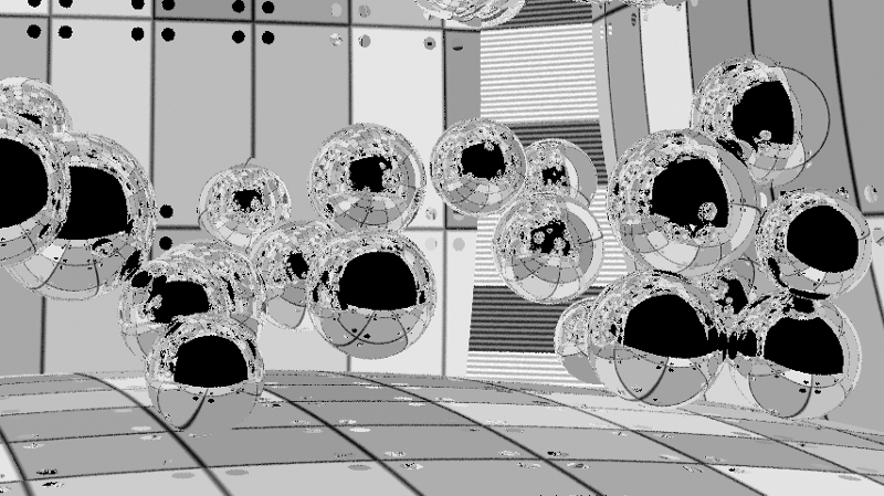
Channel textures, we do not need to blur it.
Here in the red channel contains the ID of the first object, in the green - the second, and in the blue - the third. In practice, all of them are encoded into a single value of the float format, in which the integer part stores the identifiers of objects, and the fractional one denotes roughness: 332211.RR.
Since there are objects with different roughness in the scene (some spheres are rough, on others the lighting is scattered, in the third there is a mirror reflection), I store the roughness to control the blur radius. There are no small details in the scene, so I used a large 50 x 50 kernel with the weights in the form of inverse squares to blur. It does not take into account the world space (this could be realized in order to get more accurate results), because on surfaces angled in some directions it blurs a large area. This blur creates a fairly smooth image, but still well visible artifacts, especially in motion.

Lighting channel with blur and still noticeable artifacts. In this image there are noticeable blurred points on the back wall, which are caused by a small bug with the identifiers of the second reflected object (the rays leave the scene). On the finished image, this is not very noticeable, because clear reflections are taken from the texture channel. Illumination sources also become blurred, but I liked this effect and I left it. If desired, this can be prevented by changing object identifiers depending on the material.
When objects are in the scene and the camera shooting the scene is moving slowly, the lighting in each frame should remain constant. Therefore, we can blur not only in the XY coordinates of the screen; we can blur in time. If we assume that the illumination does not change too much over 100 ms, then we can average it for 6 frames. But for this time window, the objects and the camera will still go some distance, so a simple calculation of the average for 6 frames will create a very blurry image. However, we know where all the objects and the camera were in the previous map, so we can calculate the velocity vectors in the screen space. This is called temporary reprojection. If I have a pixel at time t, then I can take the speed of this pixel and calculate where it was at time t-1, and then calculate where the pixel at time t-1 is at time t-2, and so on. back 5 frames. Unlike blur in the screen space, I used the same weight for each frame, i.e. just averaged the color between all the frames for a temporary “blur”.

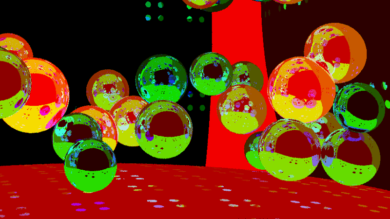
A pixel velocity channel telling where the pixel was in the last frame based on the movement of the object and the camera.

To avoid joint blurring of objects, we will again use the channel of object identifiers. In this case, we take into account only the first object that the beam encountered. This provides anti-aliasing within the object, i.e. in the reflections.
Of course, a pixel might not be visible in the previous frame; it could be hidden by another object or be out of view of the camera. In such cases, we cannot use the previous information. This check is performed separately for each frame, so we get from 1 to 6 samples or frames per pixel, and use those that are possible. The figure below shows that for slow objects this is not a very serious problem.
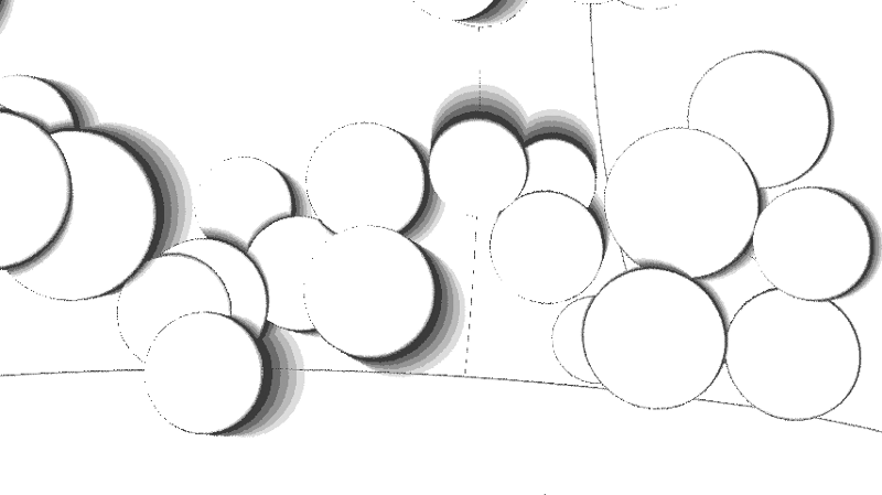
When objects move and open up new parts of the scene, we do not have 6 frames of information to average it for these parts. This image shows areas that have 6 frames (white), as well as those in which they are missing (gradually dimming shades). The appearance of the contours is caused by the randomization of the sampling locations for the pixel in each frame and the fact that we take the object identifier from the first sample.

Blurred lighting is averaged over six frames. The artifacts are almost imperceptible and the result is stable over time, because in each frame only one of six frames changes, in which the lighting is taken into account.
Combining all this, we get the finished image. Illumination is blurred by neighboring pixels, while textures and reflections remain clear. Then all this is averaged between six frames in order to create an even smoother and more stable image over time.
The finished image.
The attenuation artifacts are still noticeable, because I averaged several samples per pixel, although I took the channel of the object identifier and speed for the first intersection. You can try to fix it and get a smoothing in the reflections, discarding samples, if they do not coincide with the first, or at least if the first collision does not coincide in order. In practice, the tracks are almost invisible, so I did not bother to eliminate them. The boundaries of objects are also distorted, because the speed channels and object identifiers cannot be smoothed. I considered the possibility of rendering the entire image at a resolution of 2160p with a further decrease in scale to 1080p, but my NVidia GTX 980ti is not capable of processing such resolutions at 60fps, so I decided to abandon this idea.
In general, I am very pleased with how the intro turned out. I managed to squeeze everything I had in it, and despite the small bugs, the end result was very high quality. In the future, you can try to eliminate bugs and improve anti-aliasing. It is also worth experimenting with features such as transparency, motion blur, various shapes and object transformations.

Source: https://habr.com/ru/post/450612/
All Articles