Arduino and Processing. How to control the microcontroller on the COM port. Bilateral communication
Hello! There is a misconception on the Internet that to control a computer with home-made electronics, only special boards are needed that can be recognized as a USB HID device. And with regards to Arduino, everyone just talks about Arduino Leanardo . Such popular libraries as Keyboard and Mouse , which allow you to create an emulation of the mouse or keyboard via a microcontroller, are intended only for a pair of Arduino, Leonardo boards among them.
I will talk about how to establish communication with any Arduino microcontroller (for example, the Arduino Uno is taken) and my program at Processing. Adding to all other knowledge about Java, on which Processing is based, it will be possible to add a project under the control of the entire computer, and not just your own application. The topic of managing a computer program in Java is not something secret, google it and find everything, I assure you.
There are many integrated development environments for programming pure-C microcontrollers. Of these, the most convenient can be noted: Atollic, Eclipse, Keil.
However, for simplicity and accessibility of this guide, I will use the Arduino IDE editor and write in Arduino X. Download this editor from the official website of Arduino .
')
The development environment for programming on Procrssing can also be downloaded from the official site .
It is worth noting, for the sake of propriety, that IDE data is very similar, because it is written in one engine. And when the Arduino was created, the founders tried to simplify their code editor as much as possible, as it was done in the Processing editor.
In this example, I will use Arduino Uno. A button, a potentiometer and an LED will be connected to it. Accordingly, I can issue a logical 0 or 1. Read a logical 0 or 1. And carry out analog-digital conversion (ADC or ADC), getting numbers from 0 to 1023 (in Arduino Uno 10-bit ADC) depending on the position of the potentiometer. More for example, and not necessary, since these are the main functions that the microcontroller can do.
Connection diagram:
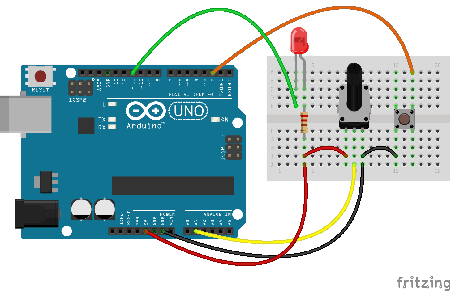
In the diagram, the anode LED is connected to 5V through a limiting resistor (at least 220 ohms, preferably 500 ohms), with a cathode to pin D11. The button closes the ground and pin D2. The potentiometer changes the potential at pin A1.
The task of the microcontroller is as follows: If the message "LED - H" comes on the serial interface (Serial COM port), light up the LED. If the message “LED - L” arrives, dim the LED. Every 250ms to send a message to the serial port (in this case on the computer screen) the message "Pot -" and the number received by analog reading of pin A1. When the button is pressed, send the message “Button is pressed!” Once.
Here is my suggestion for solving this problem (not an example to follow):
Comment: The LED is connected to the anode. This inverts the logic of the state of the LED and brings no further benefit. The button is not bound by a pull-up resistor for reasons of economy, since the Arduino Uno has built-in pull-up resistors that are included in the circuit when the pin is initialized in the INPUT_PULLUP mode.
Also in the firmware, messages about the value of the potentiometer taken from the potentiometer are sent only after the first pressing of the button!
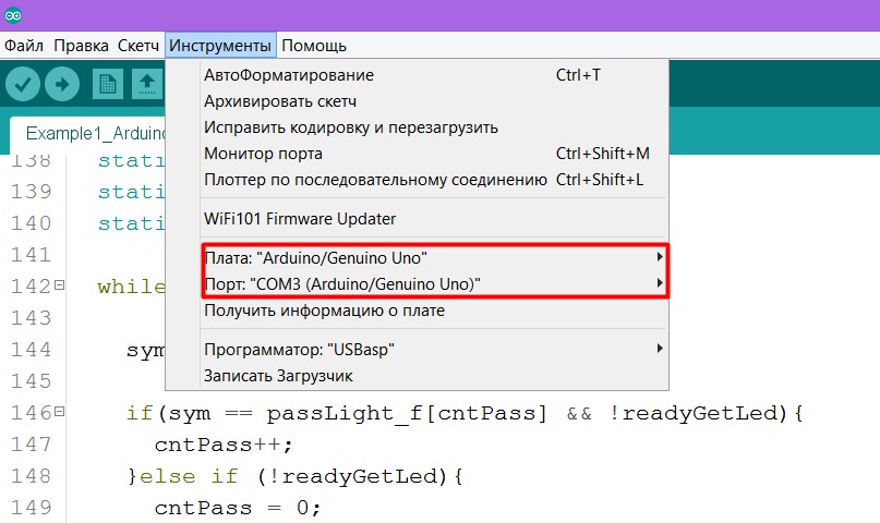
To fill the firmware into the board, do not forget to choose the port and the board.
If you do not know which COM port you have reserved for the Arduino board, then go to Windows
Control Panel -> Device Manager and click on the COM Ports tab
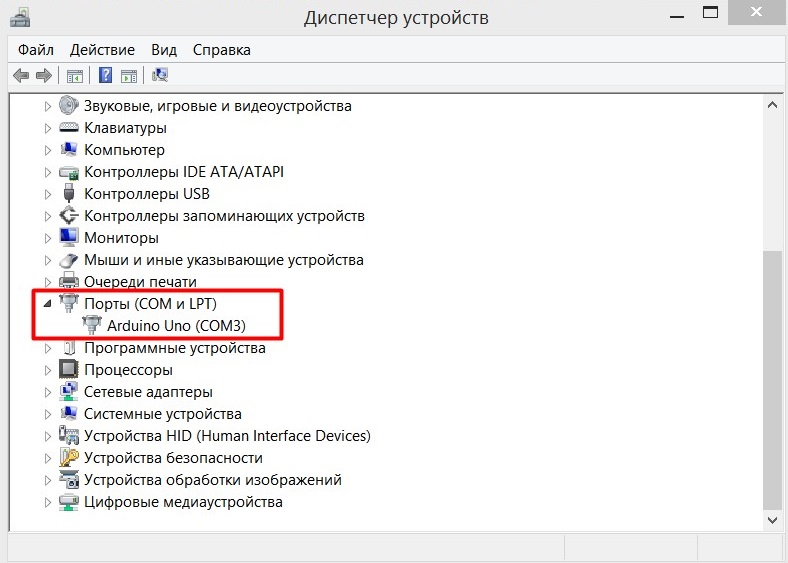
If your COM port is not signed like mine, you can always disconnect the Arduino and see which port will be lost. But if no one is missing and Arduin is not recognized by the computer at all, then it’s time to look for a solution on the Internet. But start by updating the drivers or changing the board.
When everything works out - try to open the port monitor and enter “Led - H”, “Led - L”, press the button, turn the potentiometer and look at the screen, whether everything is displayed correctly.
Have played enough - change slightly the code.
Replace the last line with the code from the comment.
Now the values from the potentiometer will not look readable, but such a maneuver is required for the Processing program.
The essence of communication programs on the Processing and the microcontroller is very simple. For this programming language there is a library Serial, which allows you to receive messages sent as
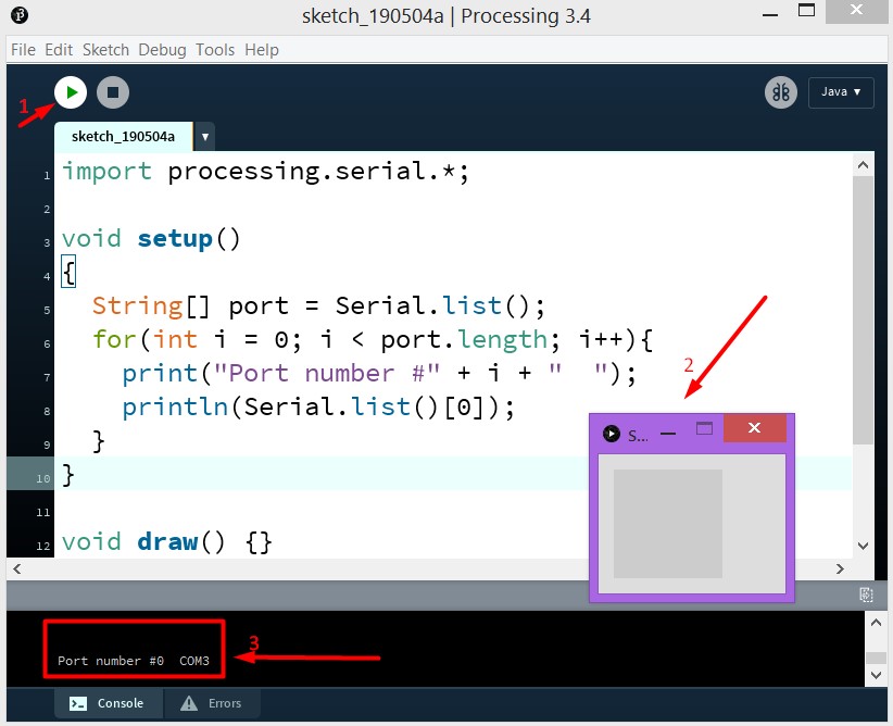
The next program will connect the Serial library and write in the editor’s console a list of all the COM ports to which you can connect.
When you write the code to the editor and click on the “Start” button (arrow 1 in the picture), an application window will appear (2) and a list of COM ports will be displayed in the console (3).
I have only one such COM port and in the list, as in the array, it will be at number 0. From these considerations, the object of class Serial:
Fill in Arduin our latest firmware with a change. Then write this program and run it. In it, every 500 milliseconds a message is sent to the COM port to extinguish or light the LED. And if everything is done correctly with you, then after the launch of the application the LED should blink.
Or here's another example. The LED will change its state after any click on the application window (the size of which is 800x800px) with the mouse button.
This elementary application simulates "flight in space", if you can call it that. The value from the potentiometer changes the flight speed, pressing the button changes the direction of flight. And any click of the mouse button on the application window changes the state of the LED (yes, I did not invent anything more original).
My code is far from perfect, do not take it as a good example. This is just an example that works. Here, actually, he.
I think it is necessary to write that I picked up the idea of the latest program from one programmer, Daniel Shiffman , who makes videos that are understandable even to children about programming in Processing ( more than 140 visual tasks have been solved ).
When I tried to figure out what to do and how to communicate with Processing and Arduino, these websites helped me a lot:
I will talk about how to establish communication with any Arduino microcontroller (for example, the Arduino Uno is taken) and my program at Processing. Adding to all other knowledge about Java, on which Processing is based, it will be possible to add a project under the control of the entire computer, and not just your own application. The topic of managing a computer program in Java is not something secret, google it and find everything, I assure you.
Download the development environment (IDE)
There are many integrated development environments for programming pure-C microcontrollers. Of these, the most convenient can be noted: Atollic, Eclipse, Keil.
However, for simplicity and accessibility of this guide, I will use the Arduino IDE editor and write in Arduino X. Download this editor from the official website of Arduino .
')
The development environment for programming on Procrssing can also be downloaded from the official site .
It is worth noting, for the sake of propriety, that IDE data is very similar, because it is written in one engine. And when the Arduino was created, the founders tried to simplify their code editor as much as possible, as it was done in the Processing editor.
Arduino. We assemble the circuit and write the code
In this example, I will use Arduino Uno. A button, a potentiometer and an LED will be connected to it. Accordingly, I can issue a logical 0 or 1. Read a logical 0 or 1. And carry out analog-digital conversion (ADC or ADC), getting numbers from 0 to 1023 (in Arduino Uno 10-bit ADC) depending on the position of the potentiometer. More for example, and not necessary, since these are the main functions that the microcontroller can do.
Connection diagram:
In the diagram, the anode LED is connected to 5V through a limiting resistor (at least 220 ohms, preferably 500 ohms), with a cathode to pin D11. The button closes the ground and pin D2. The potentiometer changes the potential at pin A1.
The task of the microcontroller is as follows: If the message "LED - H" comes on the serial interface (Serial COM port), light up the LED. If the message “LED - L” arrives, dim the LED. Every 250ms to send a message to the serial port (in this case on the computer screen) the message "Pot -" and the number received by analog reading of pin A1. When the button is pressed, send the message “Button is pressed!” Once.
Here is my suggestion for solving this problem (not an example to follow):
Firmware for Arduino Uno
#define pinPot A1 #define pinLed 11 #define pinBtn 2 void setup() { pinMode(pinPot, INPUT); pinMode(pinLed, OUTPUT); pinMode(pinBtn, INPUT_PULLUP); Serial.begin(9600); Serial.println("The program starts.\n\n"); } void loop() { /* INITIAL VARIABLES. Segment 1 */ static char potMes[] = "Pot - "; static char btnMes[] = "Button is pressed!"; static char passLight[] = "Led - "; static int passLength = sizeof(passLight) - 1; static int sizepm = sizeof(potMes) - 1; static int sizebtn = sizeof(btnMes) - 1; static bool flagLedState = LOW; static bool flagBtnPress = false; static long int curTime = 0; static const int period = 200; static bool flagEnableRead = false; /* INITIAL VARIABLES. Segment 1 */ /* FUNCTIONS CALL. Segment 2 */ /* * Led is attached to HIGH voltage from one side * And to pin on the other side * By that the inverting logic */ ReadSerialForLed(passLight, passLength, &flagLedState); digitalWrite(pinLed, !flagLedState); /* * Button pin always is pulled to the HIGH voltage * And only when button is pressed - Voltage on pin goes to GROUND * So it is need to invert logic when read pins */ if(!Bounce(pinBtn) && flagBtnPress == false){ for(int i = 0; i < sizebtn; i++){ Serial.write(btnMes[i]); } Serial.print("\n"); flagBtnPress = true; if(!flagEnableRead){ curTime = millis(); flagEnableRead = true; } }else if(Bounce(pinBtn)){ flagBtnPress = false; } /* * Read and send Info "Pot - " + var Only after first press on button * Every 'period'ms */ if(millis() - curTime > period && flagEnableRead){ SendData(pinPot, potMes, sizepm); curTime = millis(); } /* FUNCTIONS CALL. Segment 2 */ } /* * Pot - pin with potentiometer * pMes - Array with message before Pot value * sp - size of potentiometer message */ void SendData(int Pot, char* pMes, int sp){ static int varP[2]; varP[0] = analogRead(Pot); varP[1] = varP[0]/256; // 0 - 3 (256 - 1024) varP[0] = varP[0]%256; // 0 - 255 //Send Message for(int i = 0; i < sp; i++){ Serial.write(char(pMes[i])); } //Send 2 bits of data //Serial.write(varP[0]); //Serial.write(varP[1]); Serial.print(analogRead(Pot)); Serial.print("\n"); } /* * Function, which is reads button pin with the bounce */ bool Bounce(int btn){ if(digitalRead(btn) == true){ delay(15); if(digitalRead(btn) == true){ return true; }else{ return false; } }else{ return false; } } /* * If Message from Serial port, which you read will be the same to passLight * So look at the next symbol after Pass Message. If it is symbol 'H' - make LED to light * If it is 'L' - make LED off. */ void ReadSerialForLed(char *passLight_f, int passLength_f, bool* flagLedState_f){ static char sym; static int cntPass = 0; static bool readyGetLed = LOW; while (Serial.available() > 0) { sym = Serial.read(); if(sym == passLight_f[cntPass] && !readyGetLed){ cntPass++; }else if (!readyGetLed){ cntPass = 0; }else if(readyGetLed){ if(sym == 'H'){ *flagLedState_f = HIGH; }else if(sym == 'L'){ *flagLedState_f = LOW; } } if(cntPass == passLength_f){ readyGetLed = HIGH; } } }Comment: The LED is connected to the anode. This inverts the logic of the state of the LED and brings no further benefit. The button is not bound by a pull-up resistor for reasons of economy, since the Arduino Uno has built-in pull-up resistors that are included in the circuit when the pin is initialized in the INPUT_PULLUP mode.
Also in the firmware, messages about the value of the potentiometer taken from the potentiometer are sent only after the first pressing of the button!
To fill the firmware into the board, do not forget to choose the port and the board.
If you do not know which COM port you have reserved for the Arduino board, then go to Windows
Control Panel -> Device Manager and click on the COM Ports tab
If your COM port is not signed like mine, you can always disconnect the Arduino and see which port will be lost. But if no one is missing and Arduin is not recognized by the computer at all, then it’s time to look for a solution on the Internet. But start by updating the drivers or changing the board.
When everything works out - try to open the port monitor and enter “Led - H”, “Led - L”, press the button, turn the potentiometer and look at the screen, whether everything is displayed correctly.
Have played enough - change slightly the code.
Replace the last line with the code from the comment.
//Send 2 bits of data //Serial.write(varP[0]); //Serial.write(varP[1]); Serial.print(analogRead(Pot)); Now the values from the potentiometer will not look readable, but such a maneuver is required for the Processing program.
Processing. We write the program which interacts with the microcontroller
The essence of communication programs on the Processing and the microcontroller is very simple. For this programming language there is a library Serial, which allows you to receive messages sent as
Serial.write(); , and also allows you to send messages as Serial.print(); . It is important to note that if such a message is sent, it will be written to the port buffer, which means it will be read by the microcontroller. So we just need to connect to the desired Serial port and receive / send messages to it.The next program will connect the Serial library and write in the editor’s console a list of all the COM ports to which you can connect.
import processing.serial.*; void setup() { String[] port = Serial.list(); for(int i = 0; i < port.length; i++){ print("Port number #" + i + " "); println(Serial.list()[0]); } } void draw() {} When you write the code to the editor and click on the “Start” button (arrow 1 in the picture), an application window will appear (2) and a list of COM ports will be displayed in the console (3).
I have only one such COM port and in the list, as in the array, it will be at number 0. From these considerations, the object of class Serial:
Serial port; when it is created, it will be the first element of the port list that is specified port = new Serial(this, Serial.list()[0], 9600);Fill in Arduin our latest firmware with a change. Then write this program and run it. In it, every 500 milliseconds a message is sent to the COM port to extinguish or light the LED. And if everything is done correctly with you, then after the launch of the application the LED should blink.
import processing.serial.*; Serial port; // Create object from Serial class void setup(){ port = new Serial(this, Serial.list()[0], 9600); } void draw(){ delay(500); port.write("Led - H"); delay(500); port.write("Led - L"); } Or here's another example. The LED will change its state after any click on the application window (the size of which is 800x800px) with the mouse button.
import processing.serial.*; Serial port; // Create object from Serial class int cnt = 0; void setup(){ size(800, 800); port = new Serial(this, Serial.list()[0], 9600); } void draw(){} void mousePressed() { cnt++; if(cnt % 2 == 1){ port.write("Led - H"); }else{ port.write("Led - L"); } } Processing. An example of a multifunctional application
This elementary application simulates "flight in space", if you can call it that. The value from the potentiometer changes the flight speed, pressing the button changes the direction of flight. And any click of the mouse button on the application window changes the state of the LED (yes, I did not invent anything more original).
My code is far from perfect, do not take it as a good example. This is just an example that works. Here, actually, he.
An example of a multifunctional program
import processing.serial.*; Serial port; // Create object from Serial class int val; // Data received from the serial port (symbol) int pot; // Data from potentiometer String potMes = "Pot - "; String btnMes = "Button is pressed!"; int cntPM = 0; // Counter Potentiometer Message. // When it equals to length of Pot Mess - get value. int cntBM = 0; int cntBtnPress = 0; int cntMousePress = 0; Star[] stars = new Star[1000]; float speed; int dir = 1; void setup(){ size(800, 800); for(int i = 0; i < stars.length; i++){ stars[i] = new Star(); } frameRate(60); // 60 Frames per second port = new Serial(this, Serial.list()[0], 9600); // Wait for first message from Arduino delay(2000); while (port.available() > 0) { val = port.read(); print(char(val)); } } void draw(){ if (port.available() > 0) { val = port.read(); cntPM = CheckSymbol(potMes, cntPM, char(val), cntPM); cntBM = CheckSymbol(btnMes, cntBM, char(val), cntBM); } DrawRain(pot, 0, 1023); } void DrawRain(int speed_f, int min, int max){ background(0); translate(width/2,height/2); speed = dir*map(speed_f, min, max, 0, 50); for(int i = 0; i < stars.length; i++){ stars[i].go(); stars[i].update(); stars[i].show(); } } int CheckSymbol(String mes, int index, char sym, int ret_val){ if(mes.charAt(index) == sym && ret_val < (mes.length() - 1)){ return (ret_val + 1); }else if( ret_val == (mes.length() - 1) && mes.equals(potMes) ){ if(port.available() > 0){ pot = port.read(); // First 0-255 value } if(port.available() > 0){ pot += 256*port.read(); // Last 2 bits 256 - 1024 } }else if( ret_val == (mes.length() - 1) && mes.equals(btnMes) ){ cntBtnPress++; dir = -dir; } return 0; } void mousePressed() { cntMousePress++; if(cntMousePress % 2 == 1){ port.write("Led - H"); }else{ port.write("Led - L"); } } Conclusion
I think it is necessary to write that I picked up the idea of the latest program from one programmer, Daniel Shiffman , who makes videos that are understandable even to children about programming in Processing ( more than 140 visual tasks have been solved ).
When I tried to figure out what to do and how to communicate with Processing and Arduino, these websites helped me a lot:
Source: https://habr.com/ru/post/450518/
All Articles