GPU Ray Tracing in Unity - Part 3
[ First and second parts.]

Today we will make a big jump. We will move away from exclusively spherical structures and the infinite plane that we have traced earlier, and add triangles - the whole essence of modern computer graphics, the element that all virtual worlds consist of. If you want to continue with what we finished last time, then use the code from part 2 . The ready code of what we will do today is laid out here . Let's get started!
A triangle is just a list of three connected vertices , each of which keeps its position, and sometimes the normal. The order of traversing vertices from your viewpoint determines what we are looking at - the front or back edge of the triangle. Traditionally, the "front" is considered to be a counterclockwise order.
')
First, we need to be able to determine if a ray intersects a triangle, and if so, at what point. A very popular (but certainly not the only ) algorithm for determining the intersection of a ray with a triangle was proposed in 1997 by gentlemen Thomas Akenin-Möller and Ben Trembor. Details about it can be found in their article "Fast, Minimum Storage Ray-Triangle Intersection" here .
The code from the article can be easily ported to the shader code on HLSL:
To use this function, we need a ray and three vertices of a triangle. The return value tells us if the triangle intersected. In the case of intersection, three additional values are calculated:
Without undue delay, let's trace one triangle with the vertices indicated in the code! Find the
As I said,

Exercise: Try to calculate the position using the barycentric coordinates, not the distance. If you do it right, then the shiny triangle will look exactly like before.
We overcame the first obstacle, but tracing whole meshes from triangles is a completely different story. First we need to know the basic information about meshes. If you know them, you can safely skip the next paragraph.
In computer graphics, a mesh is defined by several buffers, the most important of which are vertex and index buffers. The vertex buffer is a list of 3D vectors describing the position of each vertex in object space (this means that such values do not need to be changed when moving, rotating or scaling an object - they are converted from object space to world space on the fly, using matrix multiplication) . The index buffer is a list of integer values that are indexes pointing to the vertex buffer. Every three indices make a triangle. For example, if the index buffer is [0, 1, 2, 0, 2, 3], then there are two triangles in it: the first triangle consists of the first, second and third vertices in the vertex buffer, and the second triangle consists of the first, third and fourth peaks. Therefore, the index buffer also defines the aforementioned traversal order. In addition to the vertex and index buffers, there may be additional buffers that add other information to each vertex. The most common additional buffers store the normals , texture coordinates (called texcoords or simply UV ), and vertex colors .
First of all, we need to know which GameObjects should be part of the ray tracing process. A naive solution would be to simply use
This component is added to each object that we want to use for ray tracing and is registered with
Everything is going well - now we know which objects need to be traced. But then comes the hard part: we are going to collect all the data from the Unity meshes (matrix, vertex buffers and indexes - remember them?), Write them into your own data structures and load them into the GPU so that the shader can use them. Let's start by specifying the data structures and buffers on the C # side, in the wizard:
... and now let's do the same in the shader. You are already used to this?
The data structures are ready, and we can fill them with real data. We collect all the vertices of all the meshes into one big
Call
Great, we created buffers and they are filled with the right data! Now we just need to report this to the shader. Add the following code to
So, the work is boring, but let's see what we just did: we collected all the internal data of the meshes (matrix, vertices and indices), put them in a convenient and simple structure, and then sent them to the GPU, which is now looking forward to they can be used.
Let's not keep him waiting. In the shader, we already have the trace code of a separate triangle, and the mesh is, in fact, just a multitude of triangles. The only new aspect here is that we use a matrix to transform vertices from object space to world space using the built-in
We are just one step away from seeing all this in action. Let's restructure the
That's all! Let's add some simple meshes (the Unity primitives are fine), give them the

Note that our meshes are not smooth, but flat shading. Since we have not yet loaded the vertex normal buffer, to obtain the normal of the vertex of each triangle, it is necessary to perform a vector product. In addition, we cannot interpolate over the area of a triangle. We will deal with this problem in the next part of the tutorial.
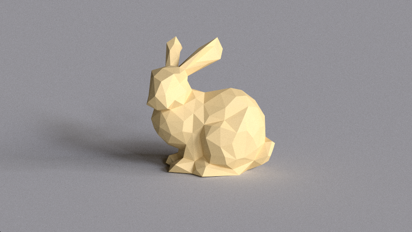
For fun, I downloaded the Stanford rabbit (Stanford Bunny) from the Morgan McGwire archive and using the decimate modifier of the Blender package reduced the number of vertices to 431. You can experiment with the lighting parameters and the strictly prescribed material in the
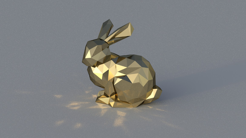
... and here is a metallic rabbit under strong directional illumination at Cape Hill , which throws disco highlights on the floor plane:
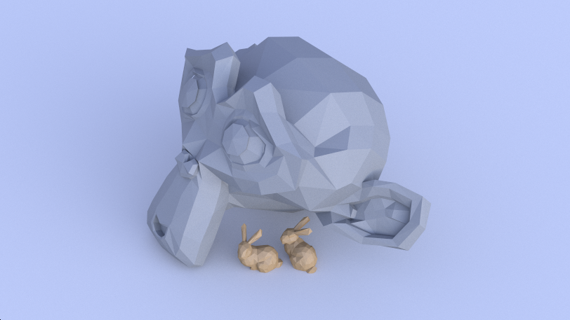
... and here are two little bunnies hiding under a big stone Suzanna under the blue sky Kiara 9 Dusk (I registered alternative material for the second object, checking if the index offset is zero):
It's great to see a real mesh in your own tracer for the first time, right? Today we processed some data, found out about the intersection using the Möller-Trembor algorithm and collected everything so that you could immediately use the GameObjects Unity engine. In addition, we saw one of the advantages of ray tracing: as soon as you add a new intersection to the code, all the beautiful effects (soft shadows, reflected and diffused global illumination, and so on) immediately begin to work.
Rendering a shiny rabbit took a lot of time, and I still had to use a bit of filtering to get rid of the most obvious noise. To solve this problem, the scene is usually recorded in a spatial structure, for example, in a grid, a K-dimensional tree or a hierarchy of bounding volumes, which significantly increases the rendering speed of large scenes.
But we need to move in order: then we will eliminate the problem with the normals, so that our meshes (even low poly) look smoother than they are now. It would also be nice to automatically update the matrices when moving objects and directly link to Unity materials, and not just register them in the code. This is what we will do in the next part of the tutorial series. Thanks for reading, and see you in part 4!
Today we will make a big jump. We will move away from exclusively spherical structures and the infinite plane that we have traced earlier, and add triangles - the whole essence of modern computer graphics, the element that all virtual worlds consist of. If you want to continue with what we finished last time, then use the code from part 2 . The ready code of what we will do today is laid out here . Let's get started!
Triangles
A triangle is just a list of three connected vertices , each of which keeps its position, and sometimes the normal. The order of traversing vertices from your viewpoint determines what we are looking at - the front or back edge of the triangle. Traditionally, the "front" is considered to be a counterclockwise order.
')
First, we need to be able to determine if a ray intersects a triangle, and if so, at what point. A very popular (but certainly not the only ) algorithm for determining the intersection of a ray with a triangle was proposed in 1997 by gentlemen Thomas Akenin-Möller and Ben Trembor. Details about it can be found in their article "Fast, Minimum Storage Ray-Triangle Intersection" here .
The code from the article can be easily ported to the shader code on HLSL:
static const float EPSILON = 1e-8; bool IntersectTriangle_MT97(Ray ray, float3 vert0, float3 vert1, float3 vert2, inout float t, inout float u, inout float v) { // find vectors for two edges sharing vert0 float3 edge1 = vert1 - vert0; float3 edge2 = vert2 - vert0; // begin calculating determinant - also used to calculate U parameter float3 pvec = cross(ray.direction, edge2); // if determinant is near zero, ray lies in plane of triangle float det = dot(edge1, pvec); // use backface culling if (det < EPSILON) return false; float inv_det = 1.0f / det; // calculate distance from vert0 to ray origin float3 tvec = ray.origin - vert0; // calculate U parameter and test bounds u = dot(tvec, pvec) * inv_det; if (u < 0.0 || u > 1.0f) return false; // prepare to test V parameter float3 qvec = cross(tvec, edge1); // calculate V parameter and test bounds v = dot(ray.direction, qvec) * inv_det; if (v < 0.0 || u + v > 1.0f) return false; // calculate t, ray intersects triangle t = dot(edge2, qvec) * inv_det; return true; } To use this function, we need a ray and three vertices of a triangle. The return value tells us if the triangle intersected. In the case of intersection, three additional values are calculated:
t describes the distance along the ray to the intersection point, and u / v are two of the three barycentric coordinates that determine the location of the intersection point on the triangle (the last coordinate can be calculated as w = 1 - u - v ). If you are not familiar with the barycentric coordinates yet, then read their excellent explanation on Scratchapixel .Without undue delay, let's trace one triangle with the vertices indicated in the code! Find the
Trace function in the shader and add the following code fragment to it: // Trace single triangle float3 v0 = float3(-150, 0, -150); float3 v1 = float3(150, 0, -150); float3 v2 = float3(0, 150 * sqrt(2), -150); float t, u, v; if (IntersectTriangle_MT97(ray, v0, v1, v2, t, u, v)) { if (t > 0 && t < bestHit.distance) { bestHit.distance = t; bestHit.position = ray.origin + t * ray.direction; bestHit.normal = normalize(cross(v1 - v0, v2 - v0)); bestHit.albedo = 0.00f; bestHit.specular = 0.65f * float3(1, 0.4f, 0.2f); bestHit.smoothness = 0.9f; bestHit.emission = 0.0f; } } As I said,
t stores the distance along the ray, and we can directly use this value to calculate the intersection point. The normal, which is important for calculating the correct reflection, can be calculated using the vector product of any two triangle edges. Launch the game mode and admire your first traced triangle:Exercise: Try to calculate the position using the barycentric coordinates, not the distance. If you do it right, then the shiny triangle will look exactly like before.
Triangle Meshes
We overcame the first obstacle, but tracing whole meshes from triangles is a completely different story. First we need to know the basic information about meshes. If you know them, you can safely skip the next paragraph.
In computer graphics, a mesh is defined by several buffers, the most important of which are vertex and index buffers. The vertex buffer is a list of 3D vectors describing the position of each vertex in object space (this means that such values do not need to be changed when moving, rotating or scaling an object - they are converted from object space to world space on the fly, using matrix multiplication) . The index buffer is a list of integer values that are indexes pointing to the vertex buffer. Every three indices make a triangle. For example, if the index buffer is [0, 1, 2, 0, 2, 3], then there are two triangles in it: the first triangle consists of the first, second and third vertices in the vertex buffer, and the second triangle consists of the first, third and fourth peaks. Therefore, the index buffer also defines the aforementioned traversal order. In addition to the vertex and index buffers, there may be additional buffers that add other information to each vertex. The most common additional buffers store the normals , texture coordinates (called texcoords or simply UV ), and vertex colors .
Using GameObjects
First of all, we need to know which GameObjects should be part of the ray tracing process. A naive solution would be to simply use
FindObjectOfType<MeshRenderer>() , but we will do something more flexible and faster. Let's add a new RayTracingObject component: using UnityEngine; [RequireComponent(typeof(MeshRenderer))] [RequireComponent(typeof(MeshFilter))] public class RayTracingObject : MonoBehaviour { private void OnEnable() { RayTracingMaster.RegisterObject(this); } private void OnDisable() { RayTracingMaster.UnregisterObject(this); } } This component is added to each object that we want to use for ray tracing and is registered with
RayTracingMaster . Add the following functions to the wizard: private static bool _meshObjectsNeedRebuilding = false; private static List<RayTracingObject> _rayTracingObjects = new List<RayTracingObject>(); public static void RegisterObject(RayTracingObject obj) { _rayTracingObjects.Add(obj); _meshObjectsNeedRebuilding = true; } public static void UnregisterObject(RayTracingObject obj) { _rayTracingObjects.Remove(obj); _meshObjectsNeedRebuilding = true; } Everything is going well - now we know which objects need to be traced. But then comes the hard part: we are going to collect all the data from the Unity meshes (matrix, vertex buffers and indexes - remember them?), Write them into your own data structures and load them into the GPU so that the shader can use them. Let's start by specifying the data structures and buffers on the C # side, in the wizard:
struct MeshObject { public Matrix4x4 localToWorldMatrix; public int indices_offset; public int indices_count; } private static List<MeshObject> _meshObjects = new List<MeshObject>(); private static List<Vector3> _vertices = new List<Vector3>(); private static List<int> _indices = new List<int>(); private ComputeBuffer _meshObjectBuffer; private ComputeBuffer _vertexBuffer; private ComputeBuffer _indexBuffer; ... and now let's do the same in the shader. You are already used to this?
struct MeshObject { float4x4 localToWorldMatrix; int indices_offset; int indices_count; }; StructuredBuffer<MeshObject> _MeshObjects; StructuredBuffer<float3> _Vertices; StructuredBuffer<int> _Indices; The data structures are ready, and we can fill them with real data. We collect all the vertices of all the meshes into one big
List<Vector3> , and all the indices into a big List<int> . There are no problems with vertices, but the indices need to be changed so that they continue to point to the correct vertex in our large buffer. Imagine that we have already added objects with 1000 vertices, and now we are adding a simple mesh cube. The first triangle can consist of indices [0, 1, 2], but since we already had 1000 vertices in the buffer, we need to shift the indices before adding the vertices of the cube. That is, they will turn into [1000, 1001, 1002]. Here is how it looks in code: private void RebuildMeshObjectBuffers() { if (!_meshObjectsNeedRebuilding) { return; } _meshObjectsNeedRebuilding = false; _currentSample = 0; // Clear all lists _meshObjects.Clear(); _vertices.Clear(); _indices.Clear(); // Loop over all objects and gather their data foreach (RayTracingObject obj in _rayTracingObjects) { Mesh mesh = obj.GetComponent<MeshFilter>().sharedMesh; // Add vertex data int firstVertex = _vertices.Count; _vertices.AddRange(mesh.vertices); // Add index data - if the vertex buffer wasn't empty before, the // indices need to be offset int firstIndex = _indices.Count; var indices = mesh.GetIndices(0); _indices.AddRange(indices.Select(index => index + firstVertex)); // Add the object itself _meshObjects.Add(new MeshObject() { localToWorldMatrix = obj.transform.localToWorldMatrix, indices_offset = firstIndex, indices_count = indices.Length }); } CreateComputeBuffer(ref _meshObjectBuffer, _meshObjects, 72); CreateComputeBuffer(ref _vertexBuffer, _vertices, 12); CreateComputeBuffer(ref _indexBuffer, _indices, 4); } Call
RebuildMeshObjectBuffers in the OnRenderImage function, and don't forget to free new buffers in OnDisable . Here are two helper functions that I used in the code shown above to slightly simplify the processing of buffers: private static void CreateComputeBuffer<T>(ref ComputeBuffer buffer, List<T> data, int stride) where T : struct { // Do we already have a compute buffer? if (buffer != null) { // If no data or buffer doesn't match the given criteria, release it if (data.Count == 0 || buffer.count != data.Count || buffer.stride != stride) { buffer.Release(); buffer = null; } } if (data.Count != 0) { // If the buffer has been released or wasn't there to // begin with, create it if (buffer == null) { buffer = new ComputeBuffer(data.Count, stride); } // Set data on the buffer buffer.SetData(data); } } private void SetComputeBuffer(string name, ComputeBuffer buffer) { if (buffer != null) { RayTracingShader.SetBuffer(0, name, buffer); } } Great, we created buffers and they are filled with the right data! Now we just need to report this to the shader. Add the following code to
SetShaderParameters (and thanks to new auxiliary functions we can reduce the code of the sphere buffer): SetComputeBuffer("_Spheres", _sphereBuffer); SetComputeBuffer("_MeshObjects", _meshObjectBuffer); SetComputeBuffer("_Vertices", _vertexBuffer); SetComputeBuffer("_Indices", _indexBuffer); So, the work is boring, but let's see what we just did: we collected all the internal data of the meshes (matrix, vertices and indices), put them in a convenient and simple structure, and then sent them to the GPU, which is now looking forward to they can be used.
Mesh tracing
Let's not keep him waiting. In the shader, we already have the trace code of a separate triangle, and the mesh is, in fact, just a multitude of triangles. The only new aspect here is that we use a matrix to transform vertices from object space to world space using the built-in
mul function (short for multiply). The matrix contains the transfer, rotation and scale of the object. It is 4 × 4 in size, so for multiplication we will need a 4d vector. The first three components (x, y, z) are taken from the vertex buffer. To the fourth component (w) we set the value 1, because we are dealing with a point. If this were a direction, then we would write 0 to it in order to ignore all the carries and scale in the matrix. Does it confuse you? Then read at least eight times this tutorial . Here is the shader code: void IntersectMeshObject(Ray ray, inout RayHit bestHit, MeshObject meshObject) { uint offset = meshObject.indices_offset; uint count = offset + meshObject.indices_count; for (uint i = offset; i < count; i += 3) { float3 v0 = (mul(meshObject.localToWorldMatrix, float4(_Vertices[_Indices[i]], 1))).xyz; float3 v1 = (mul(meshObject.localToWorldMatrix, float4(_Vertices[_Indices[i + 1]], 1))).xyz; float3 v2 = (mul(meshObject.localToWorldMatrix, float4(_Vertices[_Indices[i + 2]], 1))).xyz; float t, u, v; if (IntersectTriangle_MT97(ray, v0, v1, v2, t, u, v)) { if (t > 0 && t < bestHit.distance) { bestHit.distance = t; bestHit.position = ray.origin + t * ray.direction; bestHit.normal = normalize(cross(v1 - v0, v2 - v0)); bestHit.albedo = 0.0f; bestHit.specular = 0.65f; bestHit.smoothness = 0.99f; bestHit.emission = 0.0f; } } } } We are just one step away from seeing all this in action. Let's restructure the
Trace function a bit and add a trace of mesh objects: RayHit Trace(Ray ray) { RayHit bestHit = CreateRayHit(); uint count, stride, i; // Trace ground plane IntersectGroundPlane(ray, bestHit); // Trace spheres _Spheres.GetDimensions(count, stride); for (i = 0; i < count; i++) { IntersectSphere(ray, bestHit, _Spheres[i]); } // Trace mesh objects _MeshObjects.GetDimensions(count, stride); for (i = 0; i < count; i++) { IntersectMeshObject(ray, bestHit, _MeshObjects[i]); } return bestHit; } results
That's all! Let's add some simple meshes (the Unity primitives are fine), give them the
RayTracingObject component and watch the magic. Do not use detailed meshes yet (more than a few hundred triangles)! Our shader lacks optimization, and if you overdo it, then to trace at least one sample per pixel can take seconds or even minutes. As a result, the system will stop the GPU driver, the Unity engine may crash, and the computer will need to restart.Note that our meshes are not smooth, but flat shading. Since we have not yet loaded the vertex normal buffer, to obtain the normal of the vertex of each triangle, it is necessary to perform a vector product. In addition, we cannot interpolate over the area of a triangle. We will deal with this problem in the next part of the tutorial.
For fun, I downloaded the Stanford rabbit (Stanford Bunny) from the Morgan McGwire archive and using the decimate modifier of the Blender package reduced the number of vertices to 431. You can experiment with the lighting parameters and the strictly prescribed material in the
IntersectMeshObject shader function. Here is a dielectric rabbit with beautiful soft shadows and a small diffused global illumination in the Grafitti Shelter :... and here is a metallic rabbit under strong directional illumination at Cape Hill , which throws disco highlights on the floor plane:
... and here are two little bunnies hiding under a big stone Suzanna under the blue sky Kiara 9 Dusk (I registered alternative material for the second object, checking if the index offset is zero):
What's next?
It's great to see a real mesh in your own tracer for the first time, right? Today we processed some data, found out about the intersection using the Möller-Trembor algorithm and collected everything so that you could immediately use the GameObjects Unity engine. In addition, we saw one of the advantages of ray tracing: as soon as you add a new intersection to the code, all the beautiful effects (soft shadows, reflected and diffused global illumination, and so on) immediately begin to work.
Rendering a shiny rabbit took a lot of time, and I still had to use a bit of filtering to get rid of the most obvious noise. To solve this problem, the scene is usually recorded in a spatial structure, for example, in a grid, a K-dimensional tree or a hierarchy of bounding volumes, which significantly increases the rendering speed of large scenes.
But we need to move in order: then we will eliminate the problem with the normals, so that our meshes (even low poly) look smoother than they are now. It would also be nice to automatically update the matrices when moving objects and directly link to Unity materials, and not just register them in the code. This is what we will do in the next part of the tutorial series. Thanks for reading, and see you in part 4!
Source: https://habr.com/ru/post/450308/
All Articles