UML & Enterprise Architect: design the target process when creating an automated system

Soviet poster "Automatic production management system - the national economy!", Artist R. Suryaninov, 1972
"The story about the simulation of complex systems"
Prehistory
One of my articles on modeling a “fairy tale” subject area ( part 1 , part 2 ) was commented, I quote:
“It would be great to see a story about the modeling of precisely complex systems . ”
And I promised to pick up something from real life.
A few words about the modeling language, modeling environment, methodology and modeling agreement
Modeling language
UML is used for modeling - Unified Modeling Language, unified modeling language [1].
Simulation environment
As a modeling tool used by Enterprise Architect from the Australian company Sparx Systems [2].
Modeling Methodology and Convention
Before designing, it is necessary to establish certain rules and approaches that we will follow when developing diagrams, the same rules will be used when “reading” diagrams. The main approaches are described in detail in [3, 4].
Step 1. We develop a process map using the Use-case diagram, put all identified target processes on it - Use-case elements, as well as process participants - Actor elements, try to group the processes right away by meaning (if possible, of course).
Stage 2. We describe each process in the form of an Activity diagram. For a process in which more than 10 steps are highlighted, it makes sense to apply the principle of decomposition of the steps of the process in order to increase the readability of the diagram. For the lower level Activity diagrams, we apply the structuring of the diagram field using “swim lanes” - Swim lanes. The track name will correspond to the type of chart elements that will be placed on this track. "I / O. Objects ”: Objects elements will be located on this track - objects that are used or are the result of performing a certain process step. "Activity": here we put the elements of the Activity - the actions of participants in the process. “Role”: the track for the elements that will represent the roles of the performers of actions in our process, for them we will use the same modeling element Object - the object, but we will add the stereotype “Actor” to it. The next track is called “Rules” and on this track we place in the text form the rules for executing the steps of the process, and we will use for this purpose the modeling element Note - a note. The path "Tools" will be used to collect information about the level of automation of the process.
Stage 3. We select what can be automated. We will have three types of steps: manual, automated, and fully automatic.
Step 4. The step to be automated should be assigned to the function or functions of the system (the relationship can be many-to-many), draw a Use-case diagram. These are the functions of our system.
Stage 5. We describe the internal organization of the system using the class diagram - Class. Swimming track "I / O. Objects ”in the Activity diagram is the basis for constructing an object model and an entity-relationship model.
Step 6. We will analyze the notes on the “Rules” track; they give various kinds of restrictions and conditions, which are gradually transformed into non-functional requirements.
Stage 7. The elements on the Tools track tell us about the level of process automation.
The resulting set of diagrams gives a formalized description in a fairly strict notation, i.e. has an unequivocal reading. Now you can develop a technical task, specify the specification of requirements, etc.
Use-case modeling elements for a process map

Activity modeling elements

Brief information about the automation object
The object of automation is the process of ensuring the quality of production of medical devices.
The process of manufacturing medical devices is characterized by the presence of a large number of manual operations. Quality management is regulated in accordance with GOST ISO 13485-2011. Medical products. Quality management systems. System requirements for regulatory purposes.
To carry out quality control, it is necessary to monitor and record all operations in the manufacture of a medical product for subsequent investigation of possible incidents.
Barcode is used as a carrier of registration information. For reading information using a remote barcode reader.
The developed automated system (AS) for monitoring the manufacture of medical devices is intended for:
- control and registration of all operations in the manufacture of a medical product;
- monitoring the process of creating a product;
- receiving reports on the operations performed.
Process Map - Use-case Chart
Figure 1 shows a map of the AU processes for monitoring the manufacture of medical devices. The processes are highlighted in green, for which the following scenarios will be presented.

Figure 1. Process map of an automated system for manufacturing medical devices
Examples of process execution scripts - Activity diagrams
Figures 2-5 show examples of scenarios for the implementation of automated control processes for manufacturing medical devices.

Figure 2. Preparation for work (start of shift)

Figure 3. Production of honey. products (macro steps)
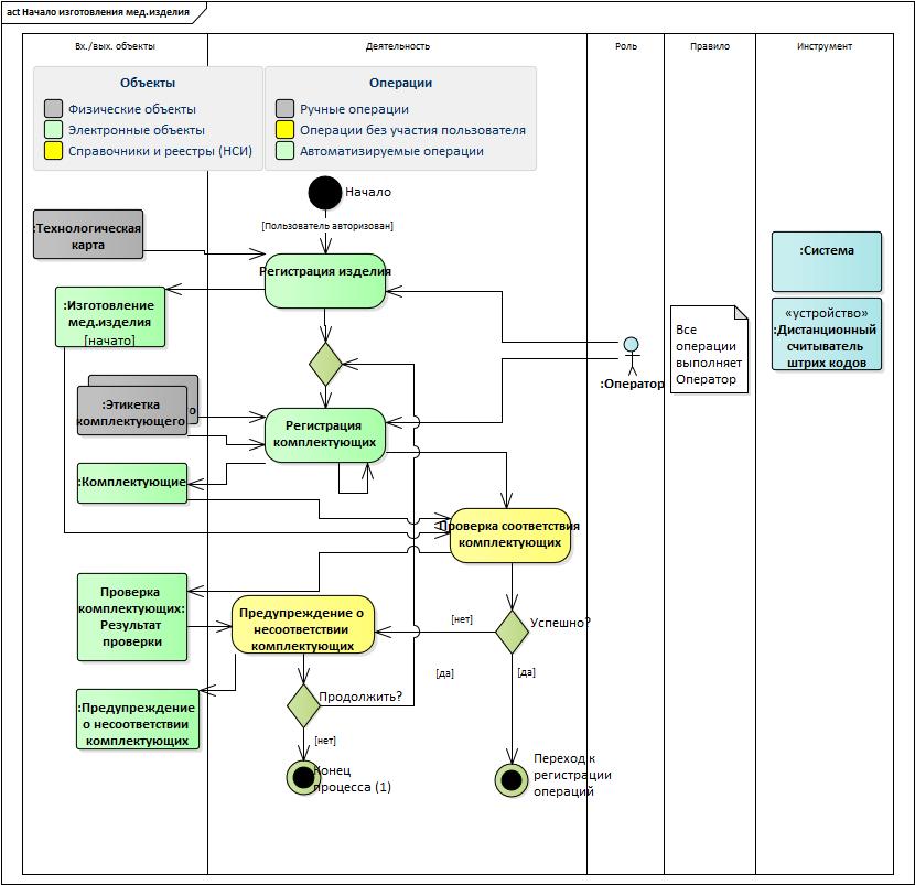
Figure 4. Start of manufacturing medical products
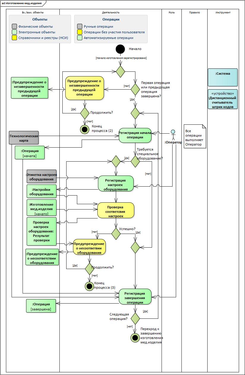
Figure 5. Manufacturing of medical products
Object Life Cycle - State Chart Chart
In the Activity diagrams, states are indicated in square brackets before or after the object names.
The full life cycle of manufacturing a medical device is presented in the State Chart (Figure 6).
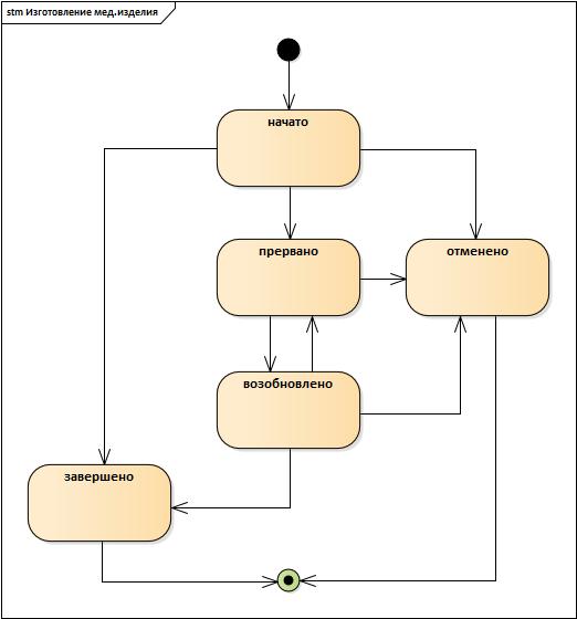
Figure 6. Diagram of manufacturing states of medical products
System structure
The system is logically divided into subsystems according to the functional attribute:
- Subsystem "Manufacturing of medical products";
- Subsystem "Directories and Registries (NSI)";
- The subsystem "Monitoring and control" (including the modules "Monitoring of technological operations" and "Reporting");
- Subsystem "Security";
- Subsystem "Administration".
Automated processes in the context of subsystems and modules are presented in the figure below (Figure 7).
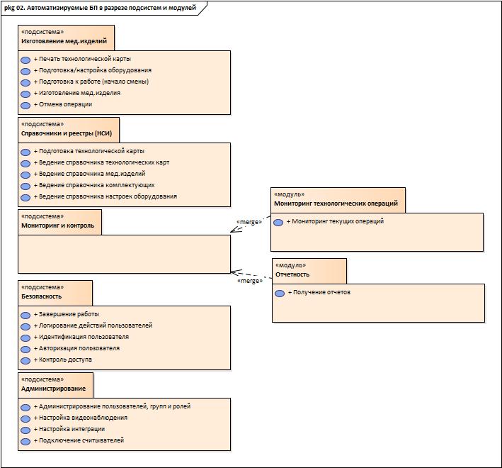
Figure 7. Automated processes in terms of subsystems and modules
This, of course, is not all diagrams, but I think it’s enough to give an idea of the model.
Instead of conclusion
When we started to develop the system, knowledge about the subject area was based only on the half-pages about medical products mentioned at the beginning of GOST ISO 13485-2011. The models were discussed with the customer; there were no particular difficulties in “reading” the models.
AU developed in 2016-2017. under SQL Server 2014 Express, on C #, ASP.NET MVC 5 platform, for front-end - Javascript and JQuery. The Mercury CL600R wireless scanners were used as remote barcode readers.
List of sources
- OMG Unified Modeling Language (OMG UML) Specification. Version 2.5.1. [Electronic resource] Access mode: Internet: https://www.omg.org/spec/UML/2.5.1/PDF
- Sparx Systems website. [Electronic resource] Access mode: Internet: https://sparxsystems.com
- Certificate No. 18249 on registration and deposit of the work of the result of intellectual activity. Alfimov R.V., Zolotukhina E.B., Krasnikova S.A. The manuscript of the educational-methodical manual called "Modeling the subject area using Enterprise Architect" // 2011.
- Zolotukhina EB, Vishnya AS, Krasnikova S.A. Business process modeling. - M .: COURSE, SEC INFRA-M, EBS Znanium.com. - 2017.
')
Source: https://habr.com/ru/post/450288/
All Articles