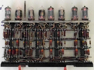
Tube bounce suppressor module from IBM 705 computer. What happens if you try to turn it on?
Spoiler: it will suppress contact bounce.

Nowadays, the bounce of contacts is most often carried out programmatically, but in some cases hardware methods continue to be used: on RC circuits and on triggers. In the 1950s, of course, there was no other choice. Many modules like this:
')

processed signals from buttons of such a remote control:

From here
Any complex scheme becomes clear if you break it into simple fragments. In this module, two types of cascades are used. The following is a slightly simplified diagram of an inverting DC amplifier:

Here the load resistor is connected between the power supply and the anode of the lamp, so the more it is open, the lower the output voltage. Such an amplifier not only amplifies the voltage, but also inverts.
At the cathode follower, a load resistor is connected between the cathode and the negative voltage source. His task is not to make changes in the amplitude of the signal, to provide a small output impedance, and therefore a large current-carrying capacity.

The author began checking the module by applying voltage to lamp heaters only. For this, he took a filament transformer (6.3 V, 2.5 A) weighing 1.5 kg.

It turned out that the heaters of all lamps are intact. All of them are double triodes, and each one has both heaters lit.
With anode circuit power supplies more difficult. The module requires three voltages: +140, -60, and -130 V, and the input signals are supposedly 48-volt (later it turned out that it did not). The available power supplies provide a maximum of ± 120 V, but the simulation in LTspice showed that at lower voltages everything will work too. The author took several power supplies, for the most part - HP devices from the Marc collection, as well as measuring equipment. Two more power supplies are not visible - they are under the table:

BP used the following types: 2 pcs. HP3068A (60 V each) - for lines -60 and -120 V, 1 pc. HP6645A - for +120 V, 1 pc. Protek 3003B (modern) - for +30 V (voltage applied to the input of the chatter suppressor through the button).
The next task is to connect conductors to the module. The corresponding connectors are not produced for 50 years, and soldering is not possible for reasons of authenticity. The module pins were approached with 0.110-inch connectors that resembled the RPPI.
To switch the supply voltages, as well as to give signals from the button, the bounce of the contacts of which is to be suppressed, the author made a small console:

We now turn to one of the bounce suppression schemes:
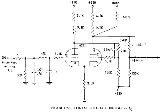
In the IBM documentation, it is called a "contact-controlled trigger." The input signal passes through the low-pass filter, then goes to the grid of the first half of the double triode, on which the inverting amplifier is assembled. The inverted signal, removed from its load resistor, is fed to the grid of the second half of the double triode through a circuit of resistors and a capacitor. Through a different resistor, a negative bias is applied to the same grid.
From the load resistor of this stage, a signal is taken to the neon on the console (for which a separate resistor is provided) and to a divider leading the signal to the following parameters: one corresponds to +30 V, zero to -10. Next, the signal arrives at a cathode repeater not shown in the diagram, which is used as a buffer. This allows you to submit it to the inputs of several cascades simultaneously located in other nodes of the machine.
The cathodes of the lamps are connected together and connected to the common wire through the same resistor. Due to this scheme acquires the properties of a Schmitt trigger. The graph shows three signals: red - multiple pulses from the contact group, green - they are after the low-pass filter, blue - after the Schmitt trigger.

The eight-lamp module under consideration contains five Schmitt triggers (each occupies one double triode), four conventional cathode repeaters (one double triode – two repeaters) and one repeater with increased load capacity (in which both lamp triodes are connected in parallel). The distribution of the functions of the lamps is shown below:
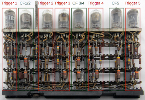
For convenience, someone else in those years struck the module with red and green inks next to the lamps on the module:

When checking out all the bounce suppression schemes, only the fourth one immediately worked. Of the rest, someone slowly took as resistors as needed. When testing, the neon and the oscilloscope were connected to the corresponding outputs. He also controlled the input signal.

A comparison of two oscillograms shows that there is a bounce in the input signal, but not in the output signal. Also, the output signal is shifted relative to the input by 1.3 ms - this contributed to the low-pass filter.
Then they tried to connect the button to the HP 5334B pulse counter - also vintage, but not so much - directly and through the bounce suppression circuit. The voltage divider collected from large resistance stores, the output pulses were "translated" into a clear "five-volt language" counter. With the direct connection of a button, every press on it counted the counter for several pulses, when connected through a module - for one.
Thanks:
Carl Claunch - per module
Paul Pierce , bitsavers and the Computer History Museum - for saved documentation for IBM 700 series computers
The author of one of the comments to the original article wrote that in the nineties he disassembled such modules: he took lamps for himself, and the rest was sold to a craftsman who drank vintage resistors and capacitors for guitar amplifiers. The attitude to vintage as to vintage, and not to a great inexhaustible donor of components, came into the mass consciousness only at the beginning of zero ...
Nowadays, the bounce of contacts is most often carried out programmatically, but in some cases hardware methods continue to be used: on RC circuits and on triggers. In the 1950s, of course, there was no other choice. Many modules like this:
')
processed signals from buttons of such a remote control:
From here
Any complex scheme becomes clear if you break it into simple fragments. In this module, two types of cascades are used. The following is a slightly simplified diagram of an inverting DC amplifier:
Here the load resistor is connected between the power supply and the anode of the lamp, so the more it is open, the lower the output voltage. Such an amplifier not only amplifies the voltage, but also inverts.
At the cathode follower, a load resistor is connected between the cathode and the negative voltage source. His task is not to make changes in the amplitude of the signal, to provide a small output impedance, and therefore a large current-carrying capacity.
The author began checking the module by applying voltage to lamp heaters only. For this, he took a filament transformer (6.3 V, 2.5 A) weighing 1.5 kg.
It turned out that the heaters of all lamps are intact. All of them are double triodes, and each one has both heaters lit.
With anode circuit power supplies more difficult. The module requires three voltages: +140, -60, and -130 V, and the input signals are supposedly 48-volt (later it turned out that it did not). The available power supplies provide a maximum of ± 120 V, but the simulation in LTspice showed that at lower voltages everything will work too. The author took several power supplies, for the most part - HP devices from the Marc collection, as well as measuring equipment. Two more power supplies are not visible - they are under the table:
BP used the following types: 2 pcs. HP3068A (60 V each) - for lines -60 and -120 V, 1 pc. HP6645A - for +120 V, 1 pc. Protek 3003B (modern) - for +30 V (voltage applied to the input of the chatter suppressor through the button).
The next task is to connect conductors to the module. The corresponding connectors are not produced for 50 years, and soldering is not possible for reasons of authenticity. The module pins were approached with 0.110-inch connectors that resembled the RPPI.
To switch the supply voltages, as well as to give signals from the button, the bounce of the contacts of which is to be suppressed, the author made a small console:
We now turn to one of the bounce suppression schemes:
In the IBM documentation, it is called a "contact-controlled trigger." The input signal passes through the low-pass filter, then goes to the grid of the first half of the double triode, on which the inverting amplifier is assembled. The inverted signal, removed from its load resistor, is fed to the grid of the second half of the double triode through a circuit of resistors and a capacitor. Through a different resistor, a negative bias is applied to the same grid.
From the load resistor of this stage, a signal is taken to the neon on the console (for which a separate resistor is provided) and to a divider leading the signal to the following parameters: one corresponds to +30 V, zero to -10. Next, the signal arrives at a cathode repeater not shown in the diagram, which is used as a buffer. This allows you to submit it to the inputs of several cascades simultaneously located in other nodes of the machine.
The cathodes of the lamps are connected together and connected to the common wire through the same resistor. Due to this scheme acquires the properties of a Schmitt trigger. The graph shows three signals: red - multiple pulses from the contact group, green - they are after the low-pass filter, blue - after the Schmitt trigger.
The eight-lamp module under consideration contains five Schmitt triggers (each occupies one double triode), four conventional cathode repeaters (one double triode – two repeaters) and one repeater with increased load capacity (in which both lamp triodes are connected in parallel). The distribution of the functions of the lamps is shown below:
For convenience, someone else in those years struck the module with red and green inks next to the lamps on the module:
When checking out all the bounce suppression schemes, only the fourth one immediately worked. Of the rest, someone slowly took as resistors as needed. When testing, the neon and the oscilloscope were connected to the corresponding outputs. He also controlled the input signal.
A comparison of two oscillograms shows that there is a bounce in the input signal, but not in the output signal. Also, the output signal is shifted relative to the input by 1.3 ms - this contributed to the low-pass filter.
Then they tried to connect the button to the HP 5334B pulse counter - also vintage, but not so much - directly and through the bounce suppression circuit. The voltage divider collected from large resistance stores, the output pulses were "translated" into a clear "five-volt language" counter. With the direct connection of a button, every press on it counted the counter for several pulses, when connected through a module - for one.
Thanks:
Carl Claunch - per module
Paul Pierce , bitsavers and the Computer History Museum - for saved documentation for IBM 700 series computers
The author of one of the comments to the original article wrote that in the nineties he disassembled such modules: he took lamps for himself, and the rest was sold to a craftsman who drank vintage resistors and capacitors for guitar amplifiers. The attitude to vintage as to vintage, and not to a great inexhaustible donor of components, came into the mass consciousness only at the beginning of zero ...
Source: https://habr.com/ru/post/450246/
All Articles