We specify the description of system functions using the Sequence diagram.
We specify the description of the functions of the system using the diagram Sequence (continuation of "Protein")
In this article, we will consider how to detail (refine) the description of the function being automated using the UML Sequence Diagram - sequence diagram.
In this example, I use the Enterprise Architect environment from the Australian company Sparx Systems [1].
For the full specification of UML, see here [2].
To begin, I will explain that we will detail.
In the first part of the article "From modeling processes to designing an automated system," we simulated the processes of the "fairy-tale" subject area - lines about a squirrel from "The Tale of Tsar Saltan" by A.S. Pushkin. And we started with the Activity chart. Then, in the second part, we developed a functional model using the Use-case diagram, Figure 1 shows a fragment.
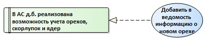
Figure 1. Communication requirements and functions
Now we want to clarify information about the implementation of this automated function:
- which interface components our user will interact with;
- what control components we need;
- what we will store;
- What messages will the user and system components exchange for executing a function?
The main elements of the Sequence diagram are interacting objects with different stereotypes and connections between them - the interacting objects exchange some information between themselves (Figure 2).

Figure 2. The main elements of the Sequence diagram
Objects are arranged in horizontal sequence, messages are transmitted between them. The time axis is oriented from top to bottom.
The Actor element can be used to represent the user initiating the event flow.
Each object has a dotted line, called the "life line", where this element exists and potentially takes part in interactions. The focus of control is indicated by a rectangle on the object's life line.
Messages that exchange objects can be of several types, messages can also be configured to reflect the operations and properties of the source and target elements.
Stereotypical elements such as borders (Boundary), controls (Control), and entities (Entity) can be used to model the user interface (GUI), controllers, and database elements, respectively.
A repeated messaging stream can be designated as a loop fragment.
So, we plan to clarify the description of the function "Add information about a new nut to the statement".
We agree on the following additional generalizations and assumptions.
- Walnut, kernel and shells are all material values of the corresponding types (Figure 3).

Figure 3. Refining the class diagram - In the statement, our user will make information about any material values.
- Specify the name of the statement - "Statement of accounting mat. Values."
- Suppose that our user, working with the GUI "Accounting List Mat. Values", can add a new Mat.value through the GUI "Accounting Card Mat. Values".
- Depending on the type of material value, the data structure and the GUI change.
- When filling in the fields of the accounting card of the material value, the validity of the entered data is checked.
The diagram, built with these assumptions, is shown in Figure 4.
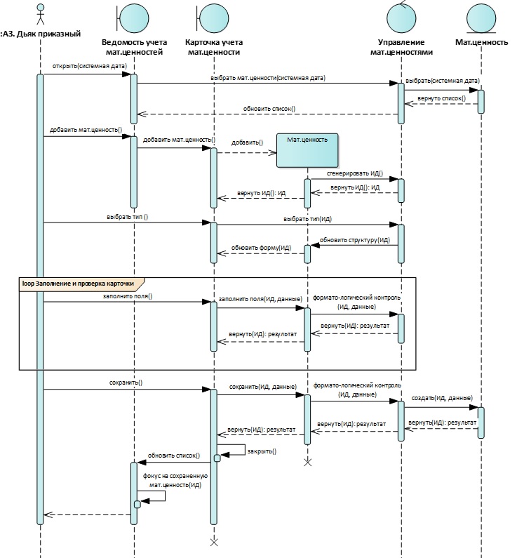
Figure 4. Refinement of the description of the function “Add new walnut information to the statement”
About the use of other types of UML diagrams can be read here:
- From process modeling to the design of an automated system (Part 1);
- From process modeling to the design of an automated system (Part 2);
- Two approaches to structuring the Activity diagram.
- Sparx Systems website. [Electronic resource] Access mode: Internet: https://sparxsystems.com
- OMG Unified Modeling Language (OMG UML) Specification. Version 2.5.1. [Electronic resource] Access mode: Internet: https://www.omg.org/spec/UML/2.5.1/PDF
')
Source: https://habr.com/ru/post/450076/
All Articles