Test drive nanoCAD SPDS Construction site 8. Part 2
Test drive nanoCAD SPDS Construction site 8
We continue to publish a test drive on the nanoCAD SPDS Construction Site. In the first part of the test drive, we analyzed the work with a special tool Project Manager, its main functions and ways to build the elements of the construction genplan. In the second part of the test drive, we will consider the construction of roads and the selection of equipment.

Theme 3. Construction of roads
In this topic, we will consider the construction of roads and their elements with the help of nanoCAD Construction site.
')
To work, you need the file "\ Topic 3_ Road construction \ Task \ Roads.dwg". In the course of the exercises of this topic, we will run all the commands from the section of the main menu “Construction Site-Roads”, therefore, further teams will be written in abbreviated form, without specifying this part of the path. To start the exercise, open the “Roads.dwg” file in the nanoCAD Construction Site.
3.1. Main road
Run the Roads command to set parameters and build roads.
In the dialogue, select the type of road "Automotive temporary roads." Pay attention to the road belonging to the construction site. The road parameters can be set in the properties and directly on the scheme. Select the size of the width of the road and install 6000 mm.
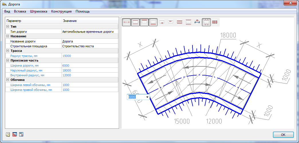
The visibility of road elements can also be configured through the View menu or directly in the figure. When you click on a road item once, it is displayed in gray and blue. When displayed in blue, it will be shown on the drawing, with gray it will not. Show the slopes, hide the dimensions and hatching, as shown in the figure. The remaining parameters can be left unchanged.
Click "OK" and enable the "Point" binding in nanoCAD, if it was not included.
Pick three points in succession to build the road. The first point is located at the lower end of the axial vertical line on the left side of the drawing. The second point is at the upper end of the center line, as shown in the figure.
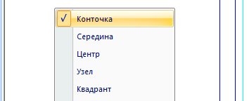
For the last point, turn on the “Middle” binding. Pick the third point by turning to the right on the other axis, as shown in the following figure. Please note that the turn is formed automatically according to the settings of the road radii.
Double-click on the road, you can call the editing dialog and hide / show its various components.
3.2. Adjoining road
Run the Roads command. In the parameters, specify the road width of 3500 mm, leave the rest unchanged, as on the main road. Make sure the nanoCAD bindings are enabled. Using the "Nearest" point to the axis of the main road, as shown in the figure.
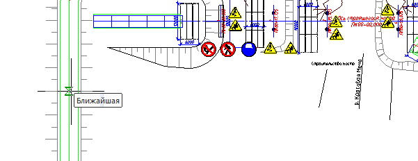
Next, build a pair of road segments, as shown in the figure.
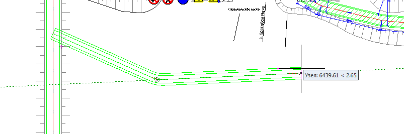
After specifying the last point, press "Enter". Please note that the intersection is formed automatically.
3.3. Reversal area
Double click on the edit dialog of the adjacent road. Go to the menu "Insert - Insert pad broadening / reversal."

In the dialog that appears, select the type of platform “Right turn platform”. Leave all parameters by default, as shown in the figure.
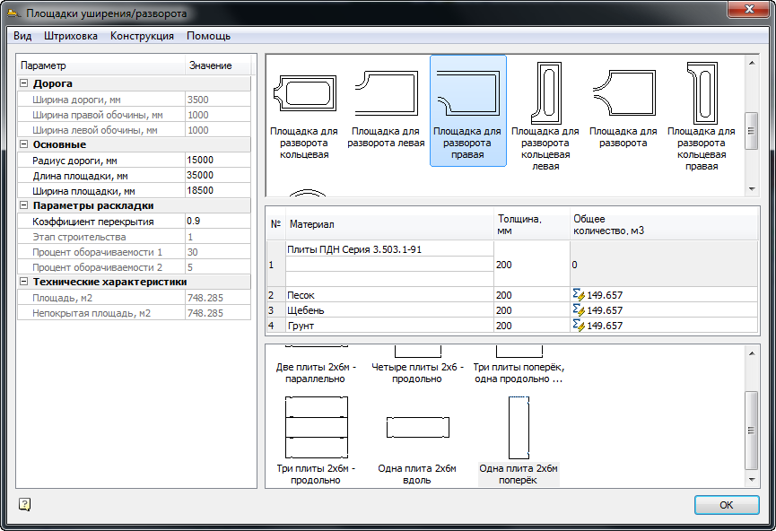
With the cursor along the road, position the site as far as possible to the right. It should turn out as shown in the figure.
3.4.Laying road plates on the road
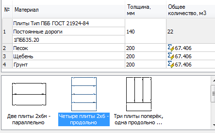
Double click into the edit dialog of the main road, which width is 6000 mm. In the dialogue, run the command "Construction - Construction of pavement". In the "Pavement Construction" window from the drop-down list of materials select plates "Plates Type PBB GOST 21924-84" and specify the brand of slabs "1PB35.20". In the layout options, select the “Two plates 2x6m parallel” icon. The remaining parameters can be left unchanged. Also note that the section geometry can be edited directly in the sketch, as in the road settings.

After adjusting the pavement design parameters, it is necessary to make an automatic layout of the road slabs. Run the "Construction - Perform Layout" command and wait until the program expands the plates.
3.5. Laying road plates at the intersection
Please note that the layout of slabs at intersections is carried out separately, because these are objects other than road objects. Double click to enter the intersection editing dialog. Select similar plates, as on the road - “Plates Type PBB GOST 21924-84” and indicate the brand of the plates “1PB3535.20”. From the layout options, select the icon “Four plates 2x6 - longitudinally”. The remaining parameters can be left unchanged. After setup, call the plate layout command via the menu “Construction - Perform Layout”.
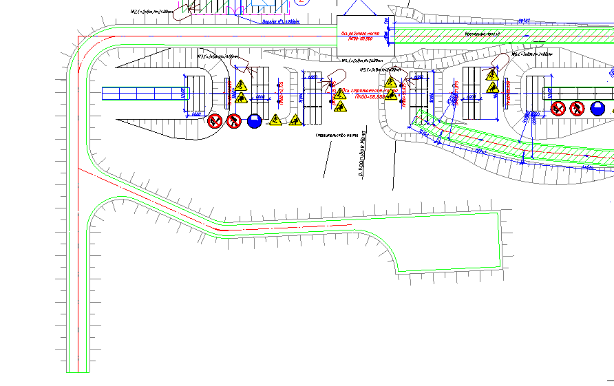
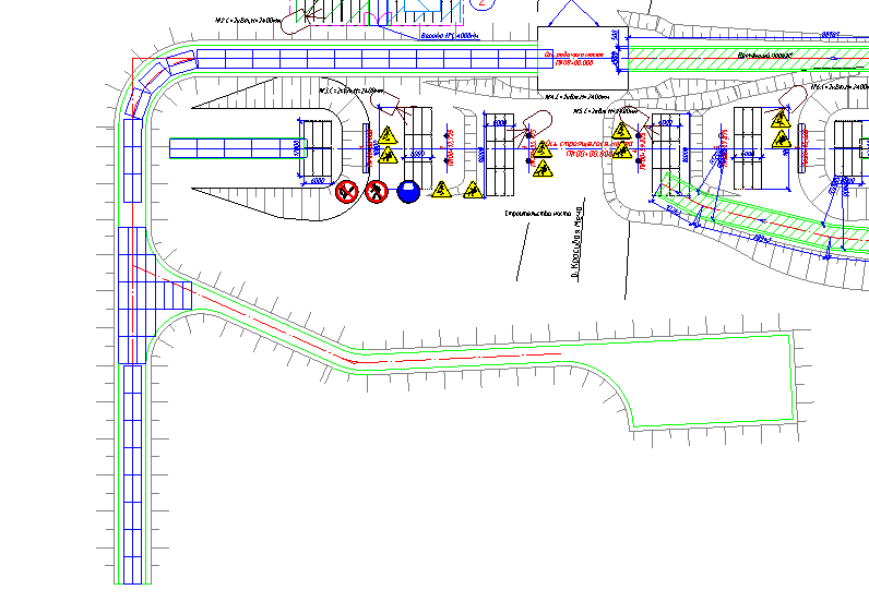
The result of the layout of the plates on the road and the intersection should be as shown in the figure.
3.6.Change layout parameters
Double click again to enter the intersection editing. Change the coefficient of overlap from 0.9 to 0.5 and perform the layout of the plates. Please note that the number of plates laid out has changed.
3.7.Installation of road signs and specification generation
Double click to enter the main road editing. In the dialog, run the command from the menu "Insert - Insert Road Sign". Wait for the database of signs to load. In the road signs dialog type “Speed” in the search field.

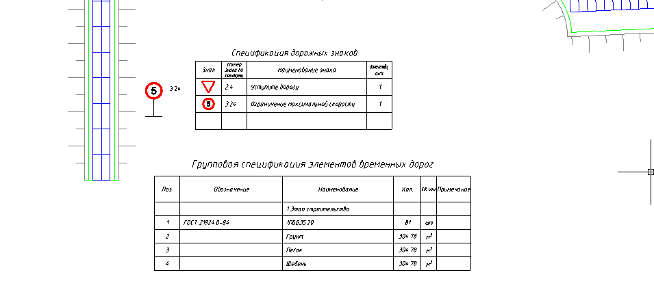
Names of characters that include this expression are highlighted in yellow. Go to the signs by the buttons to the right of the search field. Move to the second “Maximum Speed Limit” sign. Double click to select it and click "OK". Place a sign along the road at the bottom. Similarly, place a sign next to "Give way to the road." In the search bar, type the expression "Ledge" and double-click to select a sign, and then click "OK" and set it before the intersection.

To generate a specification of road signs, run the "Construction Site - Reports - Road Signs Specification" command. Place the table at the bottom of the drawing.
3.8.Specification of the elements of temporary roads
The specification can be formed by a separate road or intersection. In order for selected elements of roads to fall into a single specification, it is necessary to run the command “Construction site - Reports - Specification of roads and sites”. After launching the command, it is necessary to make a choice of those road elements along which we want to get the specification. Point to the border of the road (by default, it is indicated in green) and the border of the intersection on which the plates are laid. Place the specification at the bottom of the drawing. Materials from the specified elements of the road got to it.
Theme 4. Selection of equipment
In this topic, we will look at the functional selection of various construction equipment, depending on the specified criteria.
To work, you will need the file "\ Topic 4_Selection of equipment \ Task \ Selection of equipment.dwg".
4.1.Working machine
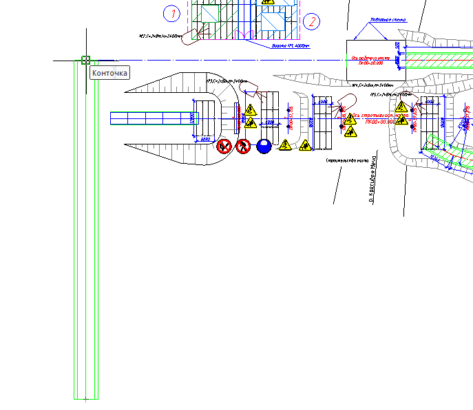
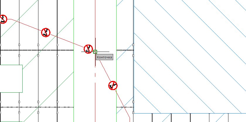
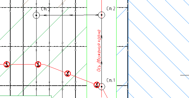
Turn on the bindings with the “Point” option and the “ORTO” mode. Run the “Construction Site - Dangerous Zones - Work and Idle” command to set the designation of the crane travel. In the dialog, select the icon "Machine running". Leave other parameters unchanged. Pick the first point at the intersection of the “Crane Restriction Line” with the axis of the road using the “Point” link, as shown in the figure.
Point to the second point at an arbitrary distance in the upward direction. Point to the third point to the right at a right angle, as shown in the figure.

4.2.Stocking crane
Select the designation of the working stroke and click on the “+” icon to add the designation of the parking of the crane. Indicate the same points that you indicated to indicate the working stroke. Must be three designations parking.
4.3. Truck tractor
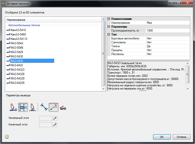
Turn on the ORTO mode. To install a saddle tractor, run the command “Construction site - Construction equipment - Selection of automotive vehicles”. In the dialogue selection technology set the following parameters. In the field “Name” specify the value “MAZ”, for all types of equipment, except for towing vehicles, set the position to “None”. In the list of filtered machines, select "MAZ-5432". In the output options, click on the icons for the top view and callout display with the name of the machine. The rest of the icons turn off.
Using the reference, specify the insertion point of the tractor on the center line of the road below the first stop and turn the cab down as shown in the figure.
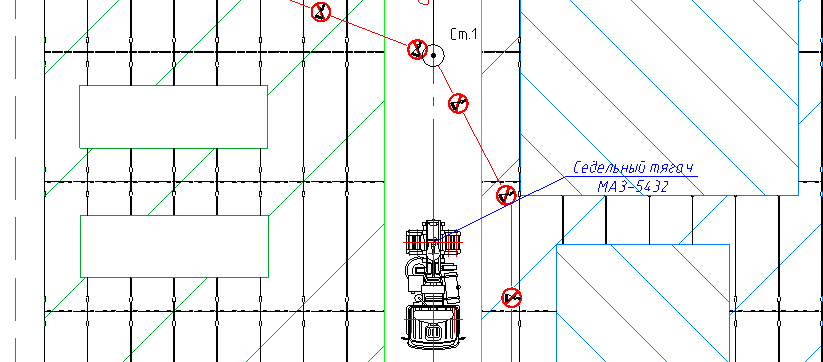
4.4.Automobile semi-trailer
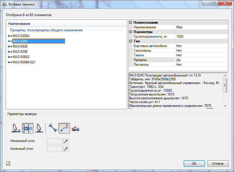
Run the command "Construction Site - Construction Equipment - Selection of automotive equipment." In the dialogue selection of equipment, set the following parameters. In the field “Name” leave the value “Maz”, for all types of vehicles, except for trailers, set the position to “No”. In the list of machines, select "MAZ - 5245". Similarly, in the output parameters, specify the top view and callout.
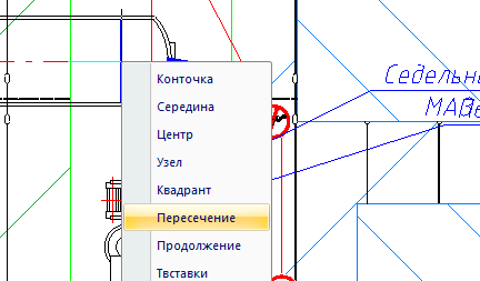
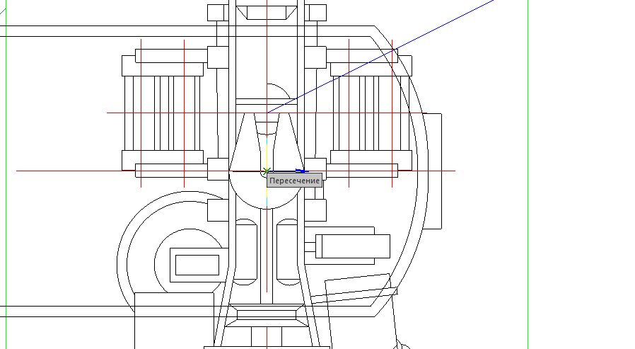
In the process of setting up a trailer, turn on the one-time binding as follows. Hold "Shift" and right-click in the model area. In the context menu, select the “Intersection” binding. Binding will be active one point indication.
Select the next point on the tractor to install the trailer, as shown in the figure.
Turn the trailer vertically up along the road axis. The result is shown below.

4.5.Car crane
Run the command “Construction Site - Construction Machinery –Selection of Lifting Equipment”. In the dialog, set only the automobile type of cranes, for the others set the value to "No". Set the lifting height to 2m and the hook departure to 5m. In the field name specify the value "COP". For cargo dimensions, set the following parameters: cargo height - 200 mm, cargo width - 2000 mm, cargo length - 3000 mm. Remaining parameters leave by default. As a result of the selection, a list of suitable cranes appears on the left. Find the crane “-3577-4” with a 14 m boom in the list. Place the cursor on the boom. In the selection options, set all the icons, except for the side view. Highlight the crane specifications and copy them to the clipboard by pressing the Ctrl + C key.

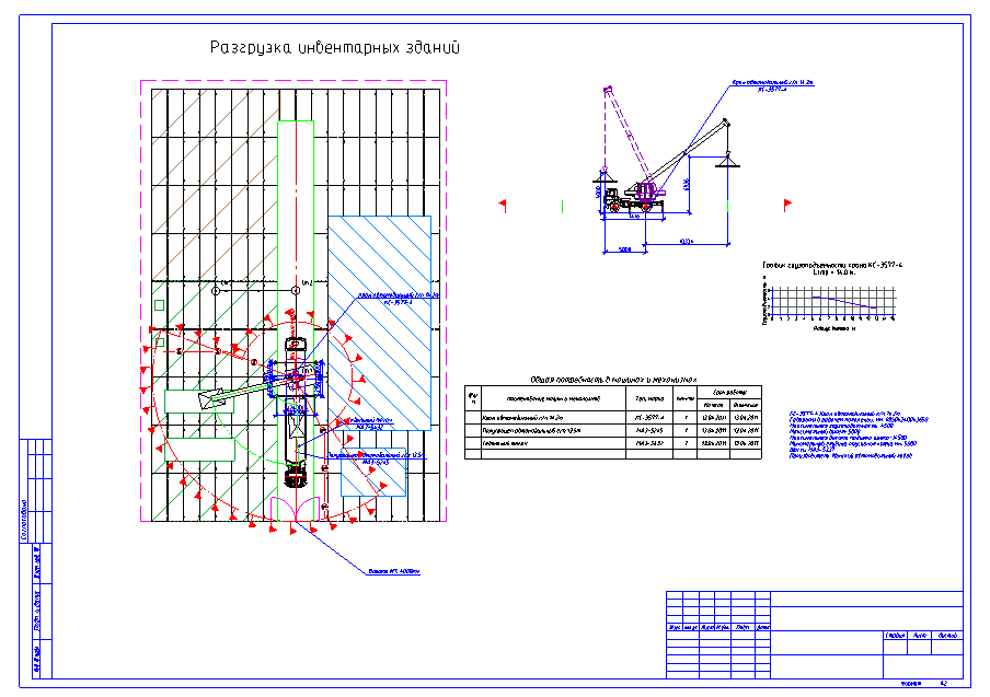
Position the side view on the right side of the drawing. Next turn on the one-time anchor Center by pressing Shift + right mouse button. Specify as the insertion point the parking of the crane No. 1. Turn the crane so that the cabin is directed upwards to the parking lot №2. In this case, the automatically enabled “Nearest” binding will help to snap to the axis of the road. After placing the crane, place the load chart also on the right side of the drawing. It should make a drawing similar to the one shown in the figure.
4.6.Technical characteristics of the crane
Call the text editor from the menu "SPDS - Text - Tech. specifications". Delete the numbered item of the first line and press Ctrl + V to paste the copied characteristics from the clipboard.
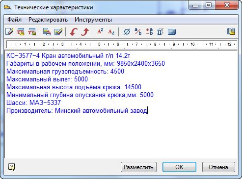
Click OK and place the text above the stamp in the drawing, indicating two diagonal points for it.
4.7.Look hooks and boom angles
Select the type of crane on the plan, pointing to his cabin, for example. You will find three characteristic handles - the axis of the crane and two departure hook. Click on the handle on the left and pull it in the middle of the semi-trailer. Similarly, pull the right-hand grip on the storage area. Please note that the working and danger zones have changed automatically.

You can also edit the section view in the same way. Take the handle located on the hook and pull it to the side. Arrange the flight at the desired distance. Pay attention to changing zones and sizes.

4.8.The danger zone of the crane
Select the dangerous zone of the crane operation with the mouse and right-click on the context menu. Call the topmost “Edit” position. The edit dialog of the danger zone opens. For the method of building the sector, select "Concentric".

Click "OK" and note the change in the shape of the danger zone.
4.9.The need for machines and mechanisms
Call the Project Manager through the menu "Construction Site - Project Manager". On the “Works” tab, place the cursor on the heading of the 3rd section “Lifting, lowering loads with self-propelled boom cranes”. Call the command "Reports - Statement of machines and mechanisms".
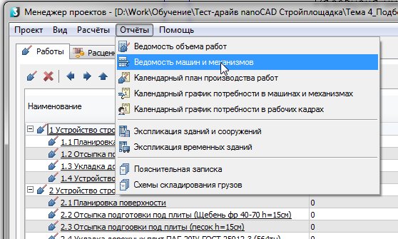
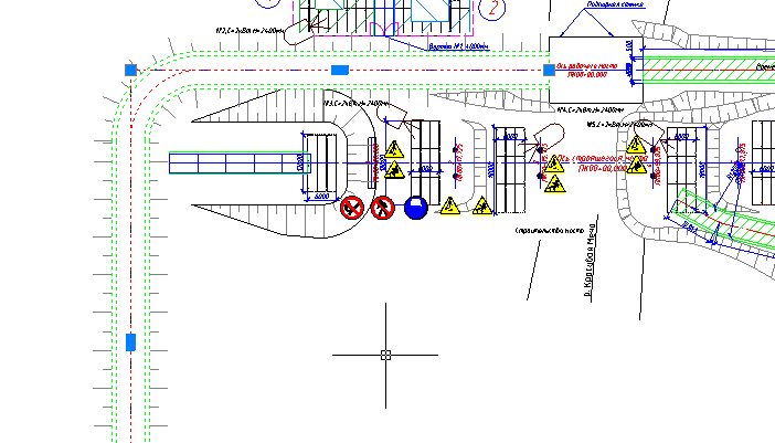
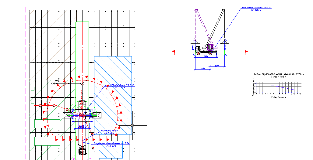
Place the bill on the drawing. The result of work in this topic is shown in the figure below.
Records of past webinars you can view on our YouTube channel .
More information on spds.club
Olga Artemyeva, Head of Software Development Department

Source: https://habr.com/ru/post/449964/
All Articles