Test drive nanoCAD SPDS Metal structures 1.2. Part 3
We continue to publish a test drive on nanoCAD SPDS Metal structures. In the first part of the test drive, we began to build a production framework. In the second part, we looked at how to create vertical ties, struts, runs and place them on the plan, as well as create a cross-section. In the final part, we will look at how to create a longitudinal section, the creation of units, the layout of drawings on sheet format and the creation of specifications.

10.1. We proceed to the construction of the section 2-2. On the SPDS toolbar, we call the command Single axis, set the axis name “1” and tick the Dimension chain (see Section 9.5).
10.2. Place the individual axes from left to right by specifying 6000 in the command line.
10.3. On the section, using the Segment command, we will show the floor level (see Section 9.8).
')
10.4. On the Metal Toolbar, we call the Column command, then in the dialog window that appears, set the necessary parameters.
In the Statement of elements tab, uncheck Include in specification and select from the list the previously created brand of column K2.

10.5. Having set all the parameters, click OK and place the column along the axis "1".
10.6. Copy the column K2 on the remaining digital axis.
10.7. We will show on the section 2-2 beams B1, for this we will call the Beam command, then in the dialog window that will appear we will set the necessary parameters.
10.8. Having set all the parameters, click OK and place the beams at the level of the top of the columns along the digital axes.
10.9. We will show the PP1 struts on the section 2-2, for this we will call the Beam command, then in the dialog window that appears we will set the necessary parameters.
10.10. Having set all the parameters, click OK and place the struts in the level of the top of the columns along the digital axes.
10.11. We will show Pr1 runs in section 2-2, for this we will call the Beam command, then in the dialog window that will appear we will set the necessary parameters.
10.12. Having set all the parameters, click OK and place the runs on the top of the beams.
10.13. In section 2-2 between axes 3-4, we will show the vertical links of CB1, for this we will call the Beam command, then in the dialog window that appears we will set the necessary parameters.
10.14. Having set all the parameters, click OK and place the connections between the columns in 3-4 axes.
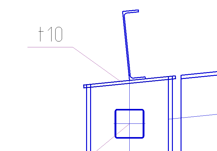
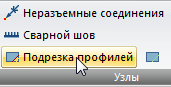
10.15. Perform the trimming of connections in the junction of the columns, for this we call the Trim Profiles command.
10.16. We specify in the quality of the contour of the trimming column.
10.17. Press Enter and indicate with the cursor the place of profile trimming. Pressing the left mouse button makes the trimming.

11.1. Create a junction of connections and struts to the column. On the Metal Toolbar, we call the Knot command, specify the base point of the node, and then the size of the node. Insert the selected fragment of the node to the free space in the drawing model.
11.2. Set the scale of the node 1:20 by selecting all the elements of the node.
11.3. Correct positioning of positional callouts and node number.
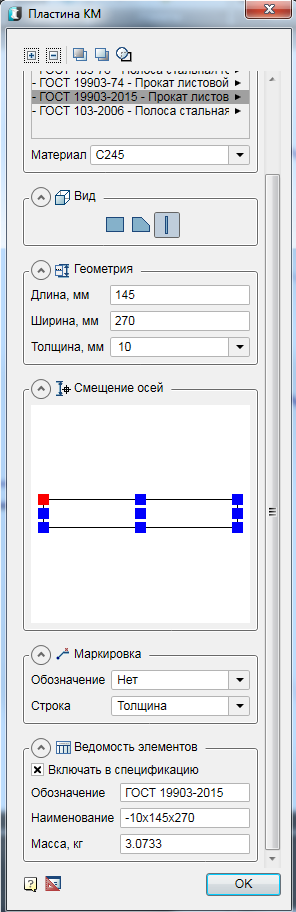
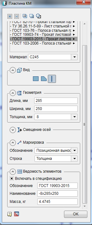
11.4. Create fasteners from the plates. Before you create a plate, set the scale of the drawing 1:20. On the Metal Toolbar, we call the Plate command, then in the dialog window that appears, set the necessary parameters.
11.6. Move the plate with the command Move down relative to other structural elements. Call the command Move down, select our plate on the node, then press Enter, then select the elements with which the comparison will go (Column K2, Communication CB1, Spacer PP1). End the command with the Enter key.

11.7. Change the mode of overlap for the plate, after selecting our plate. To better visualize the invisible contour, select our plate and change its scale to 1:10.

11.8. Using the stretch knobs, we change the length of the spacer PP1 and the coupling element CB1.
11.9. Copy the plate on the other side of the column K2 and change the length of the spacer PP1.
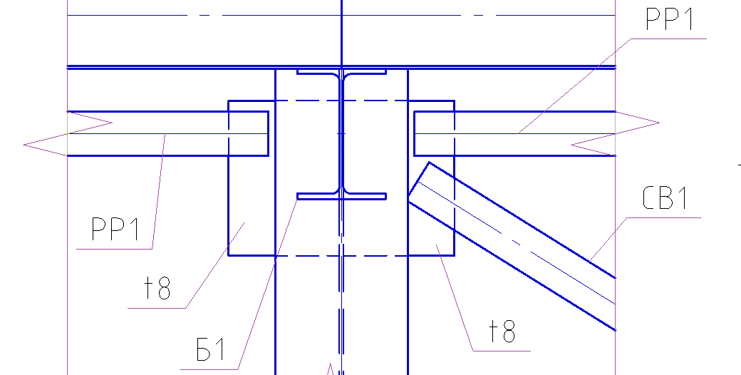
11.10. Show the stiffeners on the node. To do this, create a plate with a different type of display. On the Metal Toolbar, we call the Plate command, then in the dialog window that appears, set the necessary parameters.
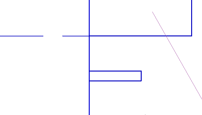
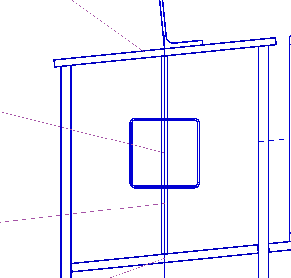
11.11. Having set all the parameters, click OK and place the plate on the node so that the plate is not completely located on the column.

11.12. Move the plate with the command Move down relative to other structural elements. Call the command Move down, select our plate on the node, then press Enter, then select the elements with which the comparison will be made (Column K2). End the command with the Enter key.
11.13. Change the mode of overlap for the plate, after selecting our plate. To better visualize the invisible contour, select our plate and change its scale to 1:10.

11.14. Move the plate to the wall of the column K2, and then copy it for the entire node.

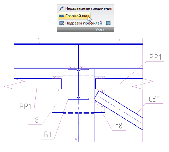
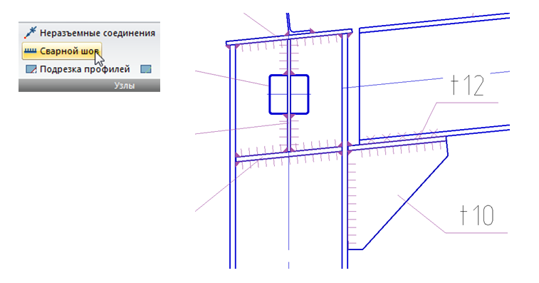
11.15. We show on the site welds.
11.16. Create a junction of the joining of the beam B1 to the column K1. Let's go to the incision 1-1. On the Metal Toolbar, we call the Knot command, specify the base point of the node, and then the size of the node. The selected fragment of the node is inserted into the free space in the drawing model.
11.17. Correct positioning of positional callouts and node number.
11.18. Create a supporting table for the beam B1. On the Metal Toolbar, we call the Plate command, then in the dialog window that appears, set the necessary parameters.
11.19. Having set all the parameters, click OK and place the plate on the node along the beam slope.
11.20. Create a support edge. On the Metal Toolbar, we call the Plate command, then in the dialog window that appears, set the necessary parameters.
11.21. Having set all the parameters, click OK and build the outline of the plate by pointing the mouse corners of the plate with the mouse cursor.

11.22. Create a plate top of the column. On the Metal Toolbar, we call the Plate command, then in the dialog window that appears, set the necessary parameters.

11.23. Having set all the parameters, click OK and place the plate on the top of the column along the beam slope.
11.24. Perform trimming of the column head, for this we call the Trim Profiles command.
11.25. We specify the tip plate as the trimming contour. Press Enter and specify the place to trim the top of the columns with the cursor. Pressing the left mouse button makes the trimming.

11.26. Copy the top plate of the support table and change its geometric dimensions.

11.27. Double-click the dialog box of the copied plate and change the length to 270 mm, width to 145 mm. Next, adjust the position of the plate.

11.28. Create a plate for mounting the strut PP1. On the Metal Toolbar, we call the Plate command, then in the dialog window that appears, set the necessary parameters.
11.29. After setting all the parameters, click OK and place the plate.
11.30. Move the vertical edge of the mount "up" relative to the cross section of the spacer PP1.

11.31. We show on the site welds.
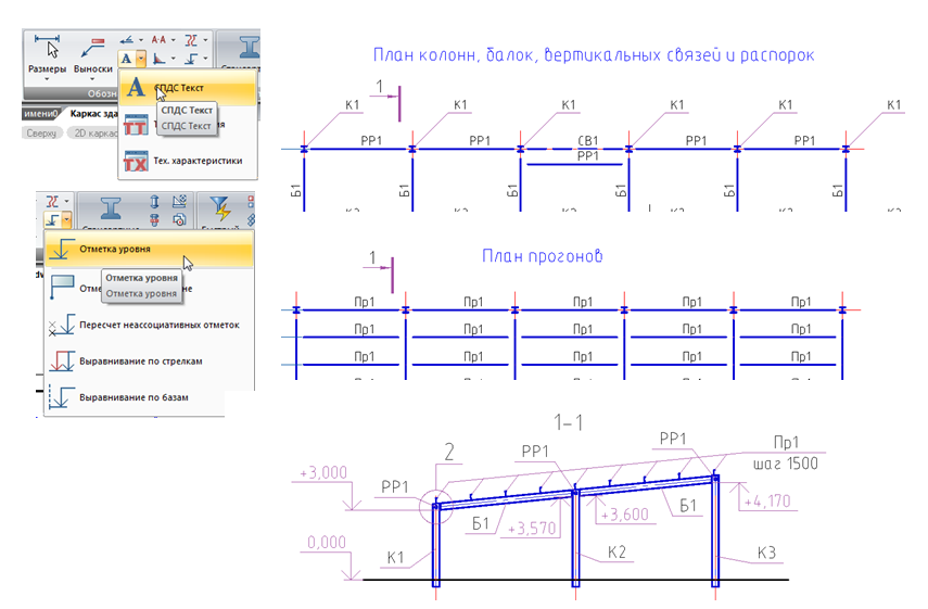
12.1. Plans and sections are created on a scale of 1: 200, and before creating a sheet format, you need to set this scale. Using the Formats tool, we will create a horizontal A3 format and place plans and sections in it.

12.2. Add names to the plans and show the elevations on the cuts.
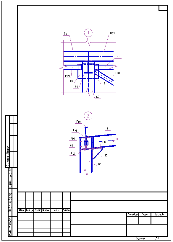
12.3 Nodes are created on a scale of 1:20 and before creating a sheet format, it is necessary to set this scale. Using the Formats tool, create a vertical A4 format and place nodes 1 and 2 in it.
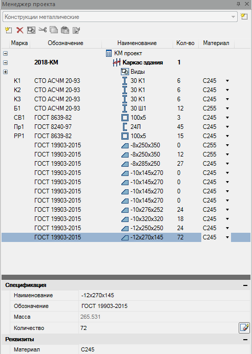
13.1. If we assume that the created nodes 1 and 2 will be the same for all frame members, in the project manager, you must manually set the number of plates that will be taken into account in the steel sheet specification.
13.2. Let's set the scale to 1: 200. Using the Formats tool, create a horizontal A3 format and place it on the drawing.
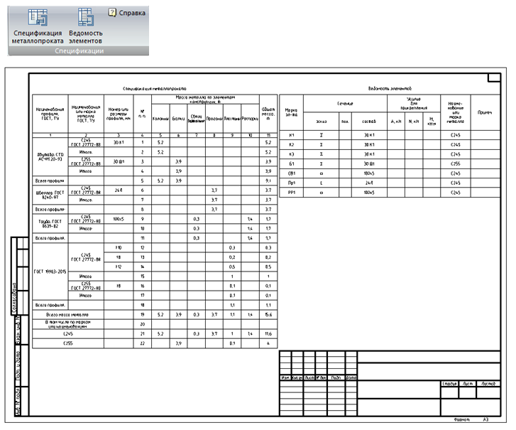
13.3. With the help of the Specification of Metal Rolling and Statement of Elements commands, we will generate these specifications and insert them into the sheet format.
Records of past webinars you can view on our YouTube channel .
More information on spds.club
 Dmitry Gostev, Leading Engineer, Magma Computer
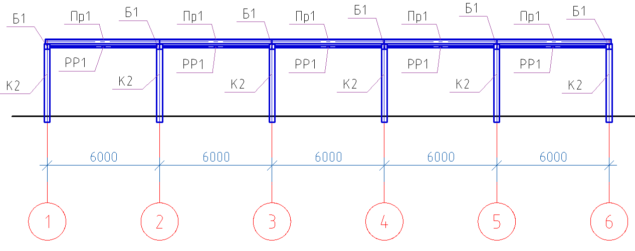
Chapter 10. Creating a Longitudinal Section
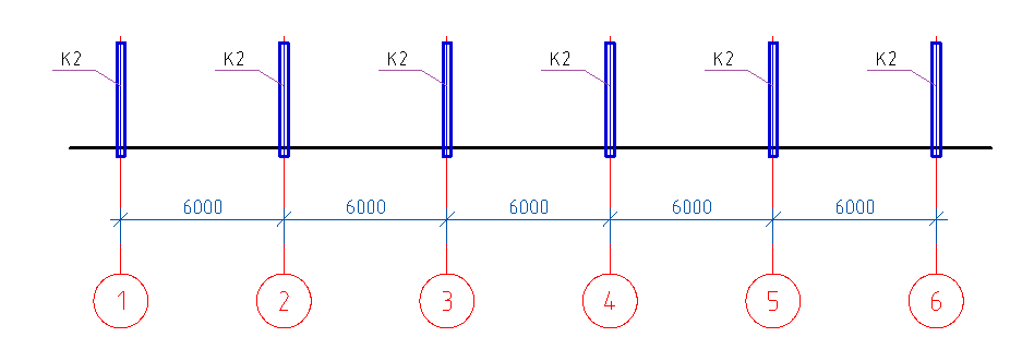
10.1. We proceed to the construction of the section 2-2. On the SPDS toolbar, we call the command Single axis, set the axis name “1” and tick the Dimension chain (see Section 9.5).
10.2. Place the individual axes from left to right by specifying 6000 in the command line.
10.3. On the section, using the Segment command, we will show the floor level (see Section 9.8).
')
10.4. On the Metal Toolbar, we call the Column command, then in the dialog window that appears, set the necessary parameters.
In the Statement of elements tab, uncheck Include in specification and select from the list the previously created brand of column K2.
- View from above".
- The display is “full”.
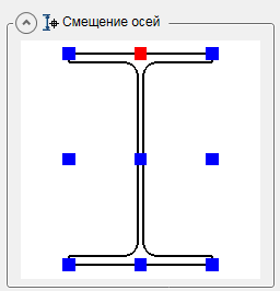
- In the Geometry tab, set the base level to -300, and the top mark to 3880.
- The Offset Axis tab is left unchanged (the center of the section).
- The Rotate tab is left unchanged (“0” rotation).
- The marking tab is left unchanged (positional callout, position).
10.5. Having set all the parameters, click OK and place the column along the axis "1".
10.6. Copy the column K2 on the remaining digital axis.
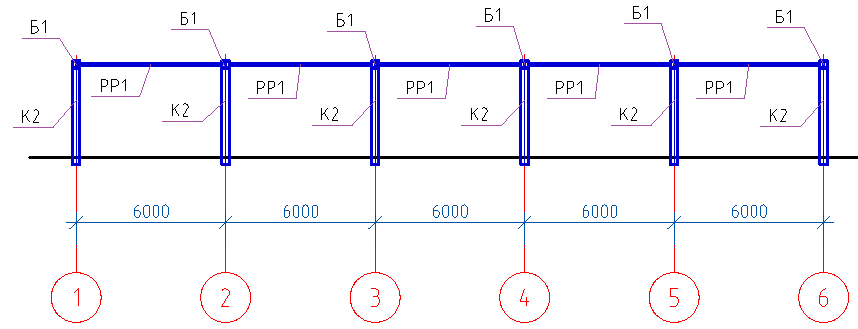
10.7. We will show on the section 2-2 beams B1, for this we will call the Beam command, then in the dialog window that will appear we will set the necessary parameters.
- In the Sheet tab of the elements select the type of the structural element Beams.
- Select the previously created brand B1.
- View - "section".
- The display is “full”.
- In the Geometry tab, leave unchanged (indicate on the drawing).
- In the Offset tab of the axes set (top center).
- In the Rotate tab, leave unchanged (turn "0").
- In the Marking tab, select the designation (positional callout).
- In the Sheet Items tab, the Include in the specification checkbox should be unchecked.
10.8. Having set all the parameters, click OK and place the beams at the level of the top of the columns along the digital axes.
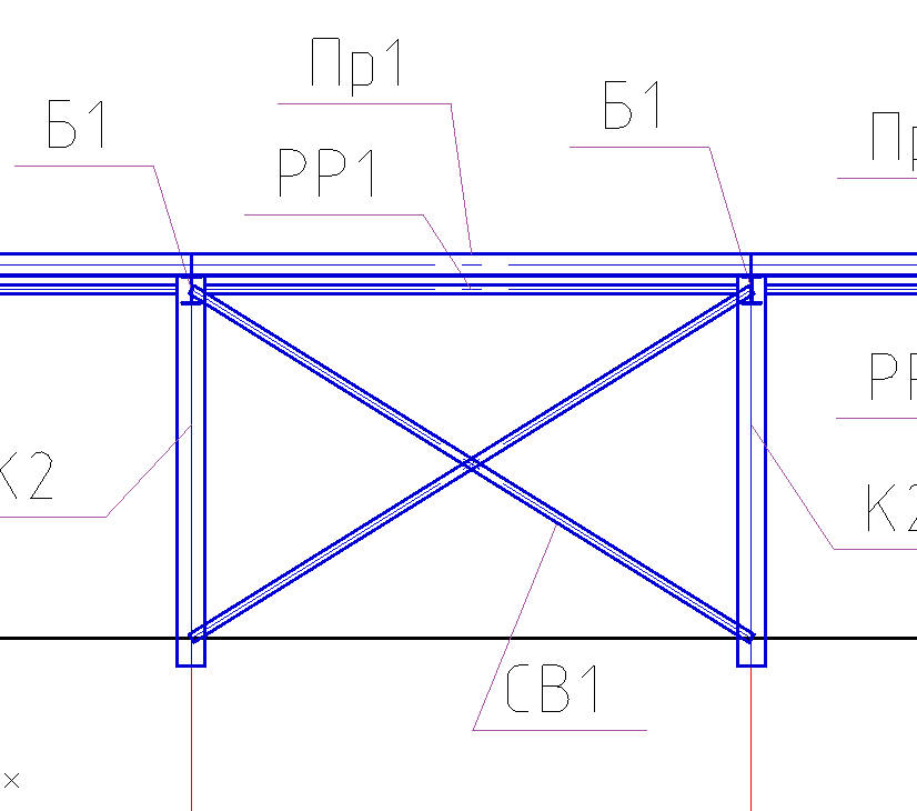
10.9. We will show the PP1 struts on the section 2-2, for this we will call the Beam command, then in the dialog window that appears we will set the necessary parameters.
- In the Sheet tab of the elements select the type of structural element of the Spacer.
- Select the previously created brand PP1.
- Front view".
- The display is “full”.
- In the Geometry tab, leave unchanged (indicate on the drawing).
- In the tab Offset axes set (center).
- In the Rotate tab, leave unchanged (turn "0").
- In the Marking tab, select the designation (positional callout).
- In the Sheet Items tab, the Include in the specification checkbox should be unchecked.
10.10. Having set all the parameters, click OK and place the struts in the level of the top of the columns along the digital axes.
10.11. We will show Pr1 runs in section 2-2, for this we will call the Beam command, then in the dialog window that will appear we will set the necessary parameters.
- In the Sheet tab of the elements select the type of the structural element Runs.
- Select the previously created brand Pr1.
- Front view".
- The display is “full”.
- In the Geometry tab, leave unchanged (indicate on the drawing).
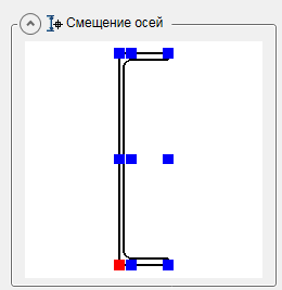
- In the tab Offset axes set (left bottom corner).
- In the Rotate tab, leave unchanged (turn "0").
- In the Marking tab, select the designation (positional callout).
- In the Sheet Items tab, the Include in the specification checkbox should be unchecked.
10.12. Having set all the parameters, click OK and place the runs on the top of the beams.
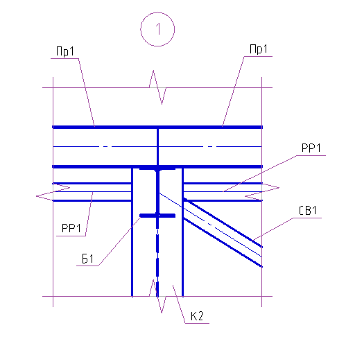
10.13. In section 2-2 between axes 3-4, we will show the vertical links of CB1, for this we will call the Beam command, then in the dialog window that appears we will set the necessary parameters.
- In the Sheet tab of the elements, select the type of the constructive element Links are vertical.
- Select the previously created brand CB1.
- Front view".
- The display is “full”.
- In the Geometry tab, leave unchanged (indicate on the drawing).
- In the tab Offset axes set (center).
- In the Rotate tab, leave unchanged (turn "0").
- In the Marking tab, select the designation (positional callout).
- In the Sheet Items tab, the Include in the specification checkbox should be unchecked.
10.14. Having set all the parameters, click OK and place the connections between the columns in 3-4 axes.
10.15. Perform the trimming of connections in the junction of the columns, for this we call the Trim Profiles command.
10.16. We specify in the quality of the contour of the trimming column.
10.17. Press Enter and indicate with the cursor the place of profile trimming. Pressing the left mouse button makes the trimming.
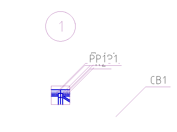
Chapter 11. Creating Nodes
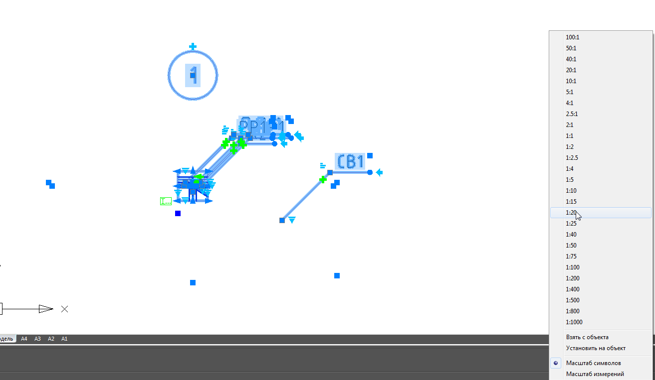
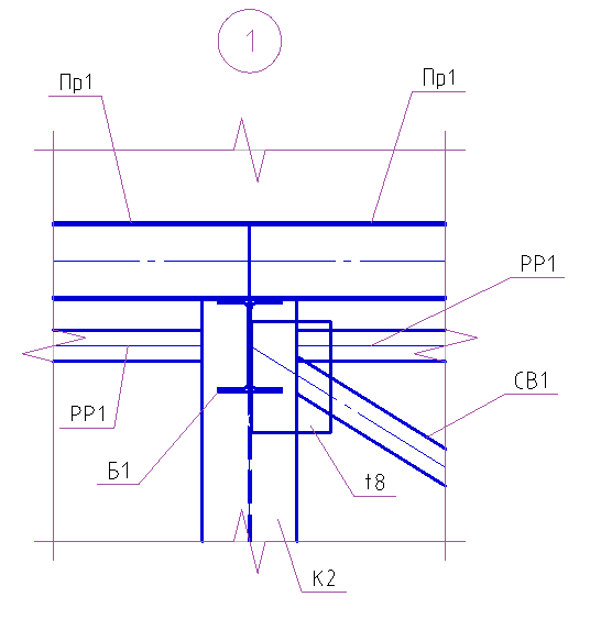
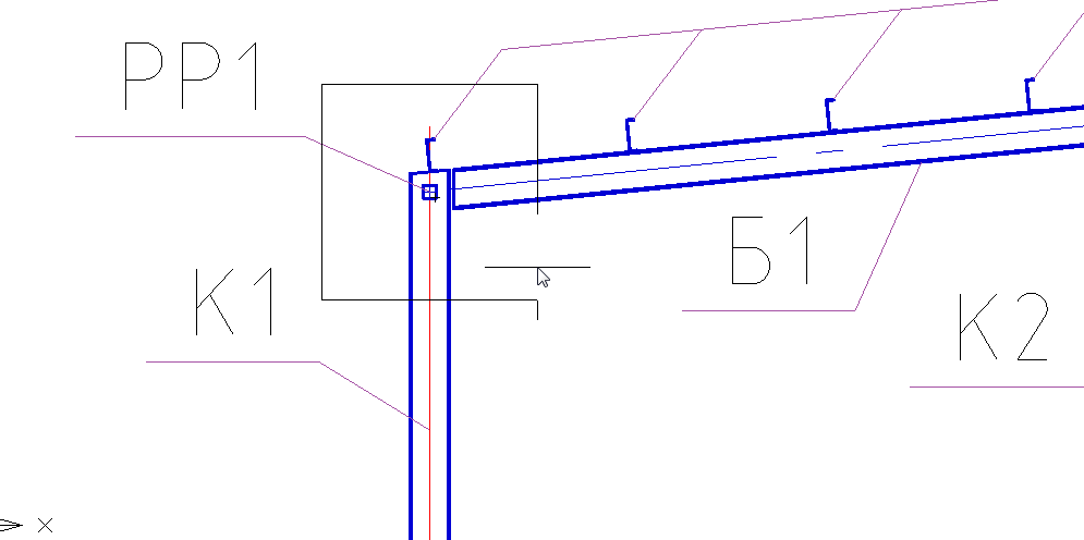
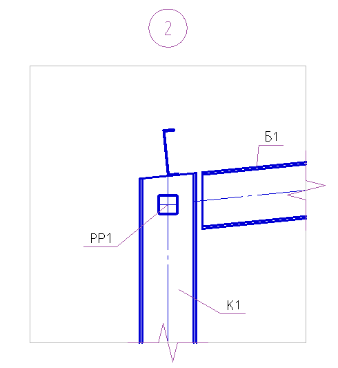
11.1. Create a junction of connections and struts to the column. On the Metal Toolbar, we call the Knot command, specify the base point of the node, and then the size of the node. Insert the selected fragment of the node to the free space in the drawing model.
11.2. Set the scale of the node 1:20 by selecting all the elements of the node.
11.3. Correct positioning of positional callouts and node number.
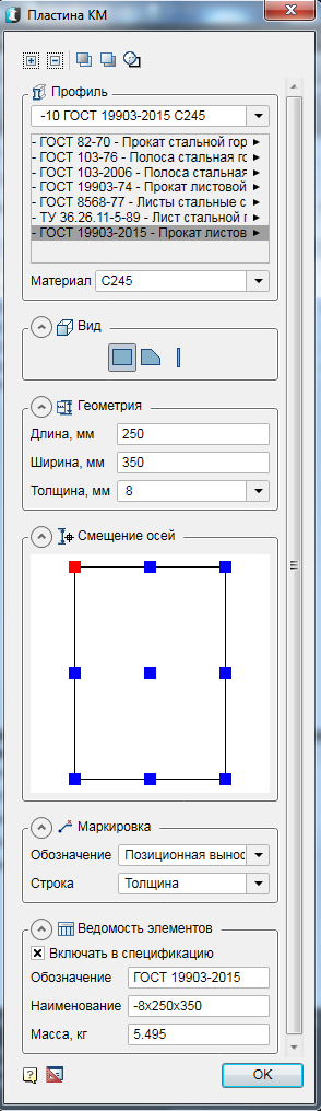
11.4. Create fasteners from the plates. Before you create a plate, set the scale of the drawing 1:20. On the Metal Toolbar, we call the Plate command, then in the dialog window that appears, set the necessary parameters.
- Select the rolled sheet profile according to GOST 19903-2015 standard with a thickness of 8 mm. C245 steel material.
- View - "rectangular."
- In the Geometry tab, specify the length and width of the plate.
- In the Axis Offset tab, we indicate the upper left corner.
- The Marking tab indicates the thickness of the plate.
- In the Sheet tab of the elements put a tick Include in the specification.
11.6. Move the plate with the command Move down relative to other structural elements. Call the command Move down, select our plate on the node, then press Enter, then select the elements with which the comparison will go (Column K2, Communication CB1, Spacer PP1). End the command with the Enter key.
11.7. Change the mode of overlap for the plate, after selecting our plate. To better visualize the invisible contour, select our plate and change its scale to 1:10.
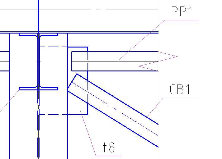
11.8. Using the stretch knobs, we change the length of the spacer PP1 and the coupling element CB1.
11.9. Copy the plate on the other side of the column K2 and change the length of the spacer PP1.
11.10. Show the stiffeners on the node. To do this, create a plate with a different type of display. On the Metal Toolbar, we call the Plate command, then in the dialog window that appears, set the necessary parameters.
- Select the sheet rolling profile according to GOST 19903-2015 standard with a thickness of 10 mm. C245 steel material.
- Side view".
- In the Geometry tab, specify the length and width of the plate.
- In the Axis Offset tab, we indicate the upper left corner.
- Tab Marking designation removed.
- In the Sheet tab of the elements put a tick Include in the specification.
11.11. Having set all the parameters, click OK and place the plate on the node so that the plate is not completely located on the column.
11.12. Move the plate with the command Move down relative to other structural elements. Call the command Move down, select our plate on the node, then press Enter, then select the elements with which the comparison will be made (Column K2). End the command with the Enter key.
11.13. Change the mode of overlap for the plate, after selecting our plate. To better visualize the invisible contour, select our plate and change its scale to 1:10.
11.14. Move the plate to the wall of the column K2, and then copy it for the entire node.
11.15. We show on the site welds.
11.16. Create a junction of the joining of the beam B1 to the column K1. Let's go to the incision 1-1. On the Metal Toolbar, we call the Knot command, specify the base point of the node, and then the size of the node. The selected fragment of the node is inserted into the free space in the drawing model.
11.17. Correct positioning of positional callouts and node number.
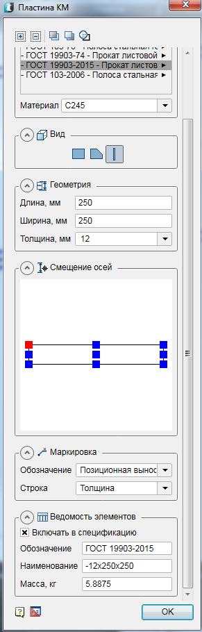
11.18. Create a supporting table for the beam B1. On the Metal Toolbar, we call the Plate command, then in the dialog window that appears, set the necessary parameters.
- Select the sheet rolling profile according to GOST 19903-2015 standard with a thickness of 12 mm. C245 steel material.
- Side view".
- In the Geometry tab, specify the length and width of the plate.
- In the Axis Offset tab, we indicate the upper left corner.
- The Marking tab indicates the thickness of the plate.
- In the Sheet tab of the elements put a tick Include in the specification.
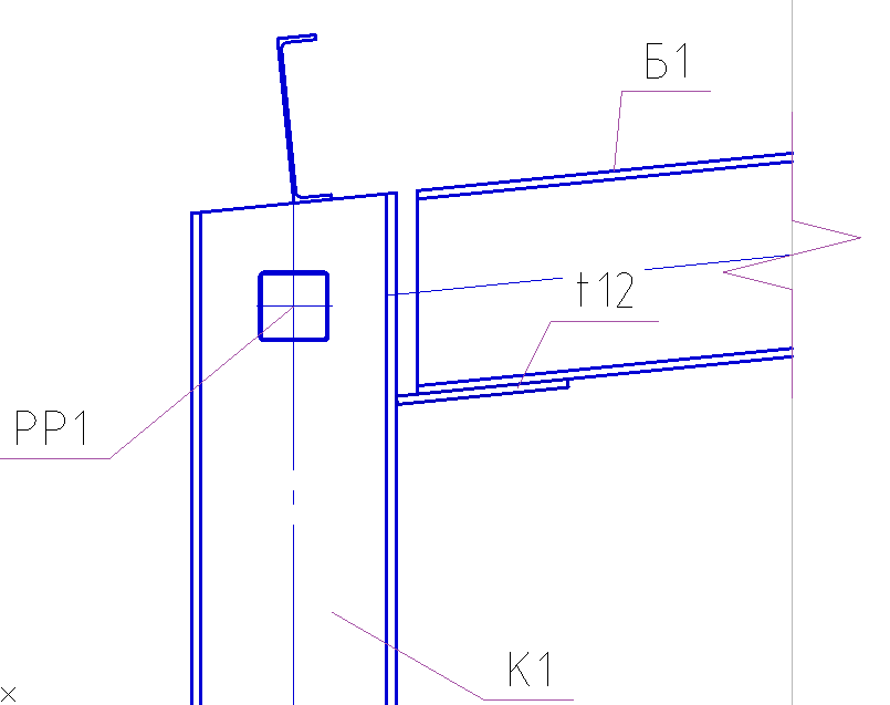
11.19. Having set all the parameters, click OK and place the plate on the node along the beam slope.
11.20. Create a support edge. On the Metal Toolbar, we call the Plate command, then in the dialog window that appears, set the necessary parameters.
- Select the sheet rolling profile according to GOST 19903-2015 standard with a thickness of 10 mm. C245 steel material.
- View - "Arbitrary outline."
- In the Geometry tab - we indicate the geometry in the drawing.
- The Marking tab indicates the thickness of the plate.
- In the Sheet tab of the elements put a tick Include in the specification.
11.21. Having set all the parameters, click OK and build the outline of the plate by pointing the mouse corners of the plate with the mouse cursor.
11.22. Create a plate top of the column. On the Metal Toolbar, we call the Plate command, then in the dialog window that appears, set the necessary parameters.
- Select the sheet rolling profile according to GOST 19903-2015 standard with a thickness of 10 mm. C245 steel material.
- Side view".
- In the Geometry tab, specify the length and width of the plate.
- In the Axis Offset tab, top center.
- The Marking tab indicates the thickness of the plate.
- In the Sheet tab of the elements put a tick Include in the specification.
11.23. Having set all the parameters, click OK and place the plate on the top of the column along the beam slope.
11.24. Perform trimming of the column head, for this we call the Trim Profiles command.
11.25. We specify the tip plate as the trimming contour. Press Enter and specify the place to trim the top of the columns with the cursor. Pressing the left mouse button makes the trimming.
11.26. Copy the top plate of the support table and change its geometric dimensions.
11.27. Double-click the dialog box of the copied plate and change the length to 270 mm, width to 145 mm. Next, adjust the position of the plate.
11.28. Create a plate for mounting the strut PP1. On the Metal Toolbar, we call the Plate command, then in the dialog window that appears, set the necessary parameters.
- Select the rolled sheet profile according to GOST 19903-2015 standard with a thickness of 8 mm. C245 steel material.
- Side view".
- In the Geometry tab, specify the length and width of the plate.
- In the tab Offset axes left center.
- The Marking tab indicates the thickness of the plate.
- In the Sheet tab of the elements put a tick Include in the specification.
11.29. After setting all the parameters, click OK and place the plate.
11.30. Move the vertical edge of the mount "up" relative to the cross section of the spacer PP1.
11.31. We show on the site welds.
Chapter 12. Layout of drawings on sheet format
12.1. Plans and sections are created on a scale of 1: 200, and before creating a sheet format, you need to set this scale. Using the Formats tool, we will create a horizontal A3 format and place plans and sections in it.
12.2. Add names to the plans and show the elevations on the cuts.
12.3 Nodes are created on a scale of 1:20 and before creating a sheet format, it is necessary to set this scale. Using the Formats tool, create a vertical A4 format and place nodes 1 and 2 in it.
Chapter 13. Creating Specifications
13.1. If we assume that the created nodes 1 and 2 will be the same for all frame members, in the project manager, you must manually set the number of plates that will be taken into account in the steel sheet specification.
13.2. Let's set the scale to 1: 200. Using the Formats tool, create a horizontal A3 format and place it on the drawing.
13.3. With the help of the Specification of Metal Rolling and Statement of Elements commands, we will generate these specifications and insert them into the sheet format.
Congratulations! You have successfully completed a trial test drive on the capabilities of nanoCAD DPS Metal Structures 1.2!
We invite you to take part in the free webinar “SPDS Metal Structures . Construction of a metal platform on a pile foundation ".
The purpose of the webinar is to demonstrate to CAD users how the efficiency of the work of design engineers is increased when using the specialized software for the DPS Metalwork. Within the framework of the webinar, a new program functionality will be demonstrated, namely, a new team for the creation of piles for various purposes. The program implements new parametric objects: reinforced concrete piles, steel piles of pipes intended for the construction of supports for oil pipelines, bridge supports, high-voltage power lines for antenna, mast structures, open switchgears, machines and mechanisms with dynamic loads, communication lines and other structures, according to project documentation in thawed, with seasonal freezing and permafrost soils. The functionality of the program performs automatic numbering of piles and automatically generates a specification for the pile and a group specification for the pile field.
Records of past webinars you can view on our YouTube channel .
More information on spds.club
Dmitry Gostev, Leading Engineer, Magma ComputerSource: https://habr.com/ru/post/449922/
All Articles