Cable TV networks for the smallest. Part 1: The overall architecture of the CATV network

As if the enlightened community did not scold television for a negative impact on consciousness, however, the television signal is present in almost all residential (and in many non-residential) premises. In big cities, this is almost always cable television, even if everyone around is out of habit called it “antenna”. And if the system for receiving on-air television is quite obvious (although it may also differ from the usual horned antenna on the windowsill, I will definitely tell about this later), then the cable television system may seem surprisingly difficult in its work and architecture. About this present a series of articles. I want to acquaint those interested in the principles of operation of KTV networks, as well as their operation and diagnostics.
Content of a series of articles
- Part 1: The overall architecture of the CATV network
- Part 2: Composition and waveform
- Part 3: Analog Signal Component
- Part 4: The digital component of the signal
- Part 5: Coaxial distribution network
- Part 6: RF Amplifiers
- Part 7: Optical Receivers
- Part 8: Optical Trunk Network
- Part 9: Head Station
- Part 10: Troubleshooting on a CATV network
I do not pretend to write a comprehensive textbook, but I will try to stay within the framework of a scientific journal and not overload articles with formulas and descriptions of technologies. That is why I left in the text "smart" words without explanation, googling on them you will be able to go as far as you need. After all, individually everything is well described, and I will only tell you how it all adds up to a cable television system. In the first part, I will describe the network structure superficially, and in the future I will review in more detail the principles of the entire system.
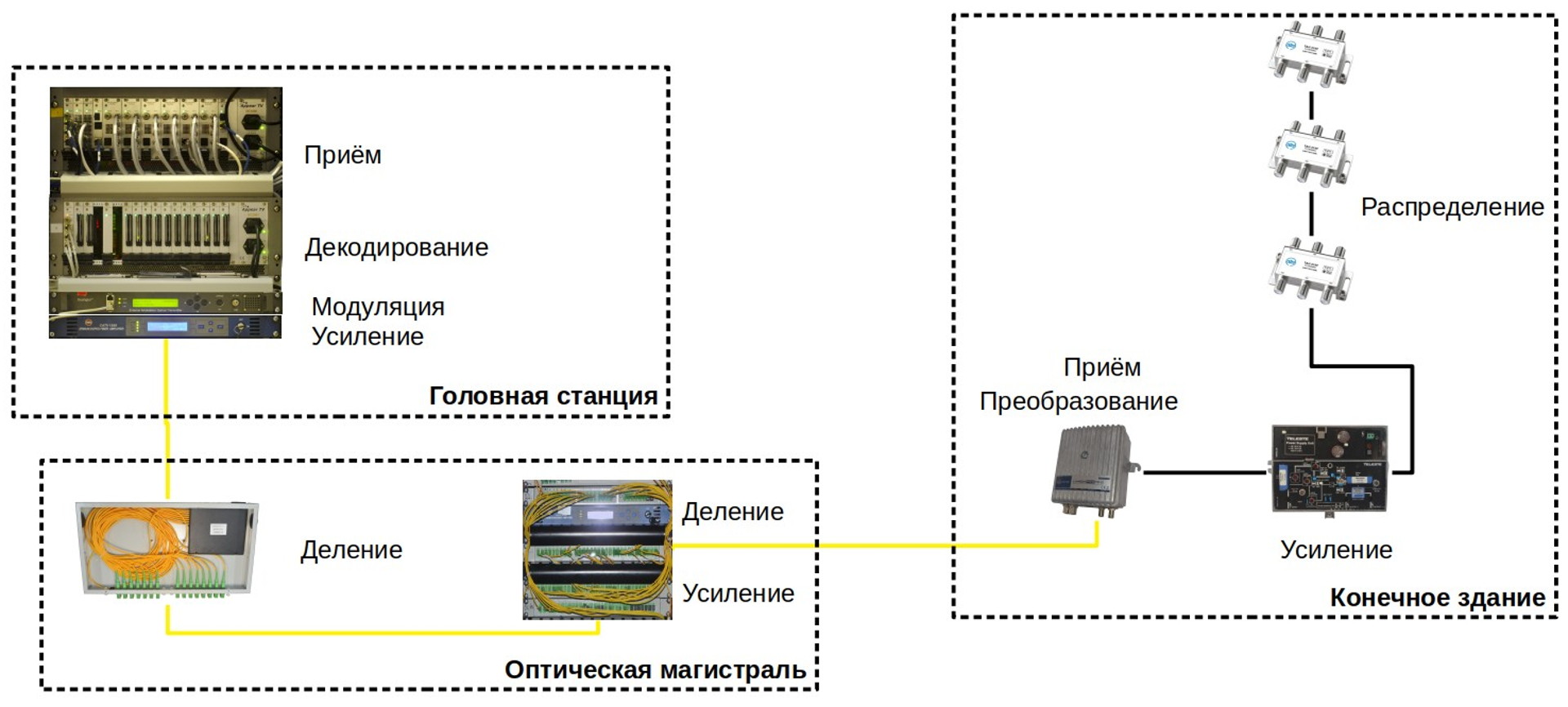
The cable television network has a tree structure. The signal is formed by the head station, which collects signals from different sources, forms one of them (according to a predetermined frequency plan) and gives it to the main distribution network in the required form. Today, the backbone network is, of course, optical and the signal goes to coaxial cable only within the final building.
')
Head station
Signal sources for the head station can be either satellite antennas (of which there may be a dozen), or digital streams sent directly by TV channels or other telecom operators. For receiving and assembling a signal from different sources, multichannel multiservice decoders / modulators are used, which are rack-mount chassis with various expansion cards providing connection of various interfaces, as well as decoding, modulating and generating the desired signal.
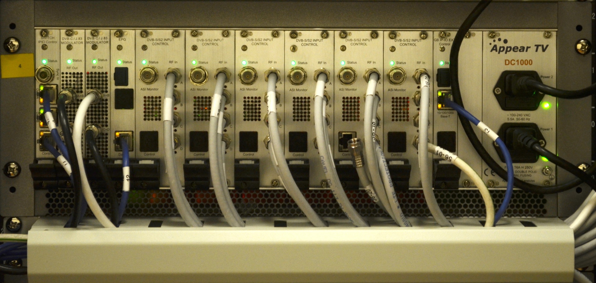
Here, for example, we see 6 satellite broadcast signal receiving modules and two DVB-C output modulators.
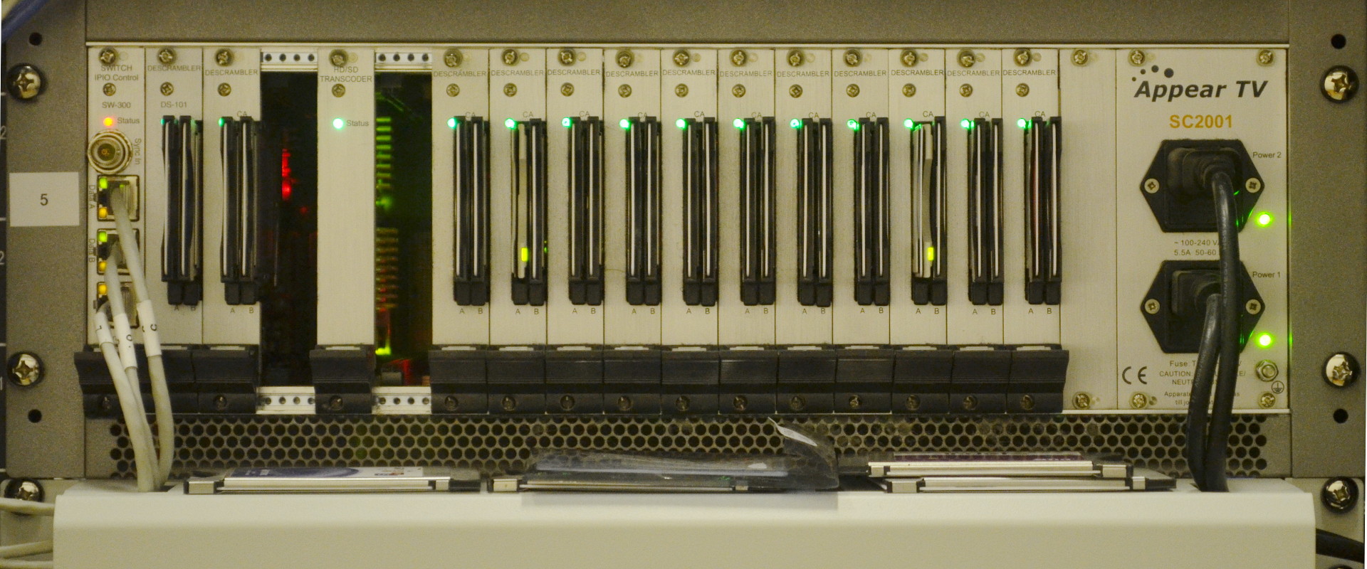
And this chassis is engaged in signal descrambling. It can be seen CAM modules, the same as inserted into the TV to receive closed channels.
The result of the work of this equipment is the output signal containing all the channels that we will give to subscribers, decomposed into frequencies in accordance with a given frequency plan. In our network it is the range from 49 to 855 MHz, containing both analog channels and digital channels in DVB-C, DVB-T and DVB-T2 formats:
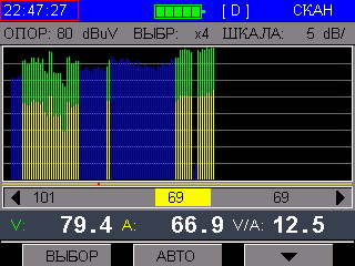
Signal spectrum display.
The generated signal is fed to an optical transmitter, which is essentially a media converter and transfers our channels into the optical medium to the traditional television wavelength of 1550nm.

Optical transmitter.
Main distribution network
The optical signal received from the headend is amplified by an optical erbium amplifier (EDFA) familiar to any signaller.

A couple dozen dBm of the signal level taken from the amplifier output can already be divided and sent to different areas. The division is made by passive dividers, for convenience, laid in the housing rack mounts.
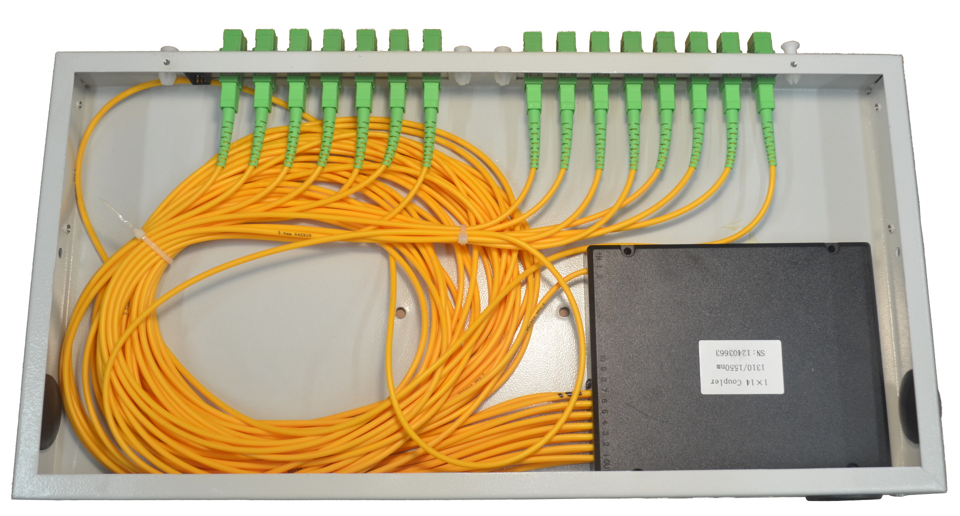
Optical divider inside single-unit optical cross.
The divided signal gets to the objects, where it can be reinforced with the help of the same amplifiers, or divided between other equipment, if necessary.
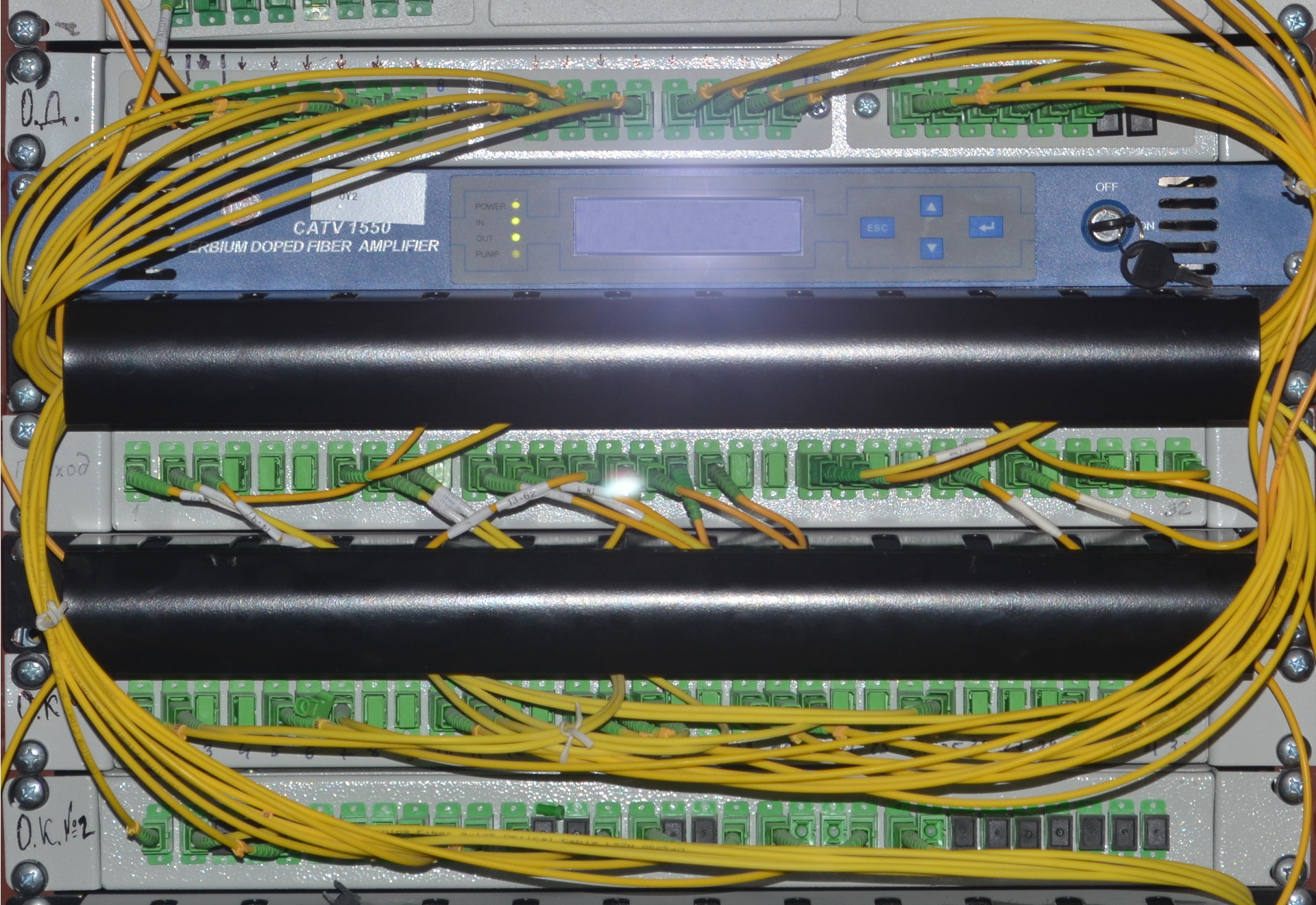
So may look node residential quarter. It includes an optical amplifier, a signal divider in the rack-mount cross, and an optical distribution cross, from which the fibers diverge to the optical receivers.
Subscriber Distribution Network
Optical receivers, like the transmitter, are medium converters: they transfer the received optical signal to a coaxial cable. OPs are different and different manufacturers, but their functionality is usually the same: level monitoring and basic signal adjustments, which I will discuss in detail in the following articles.
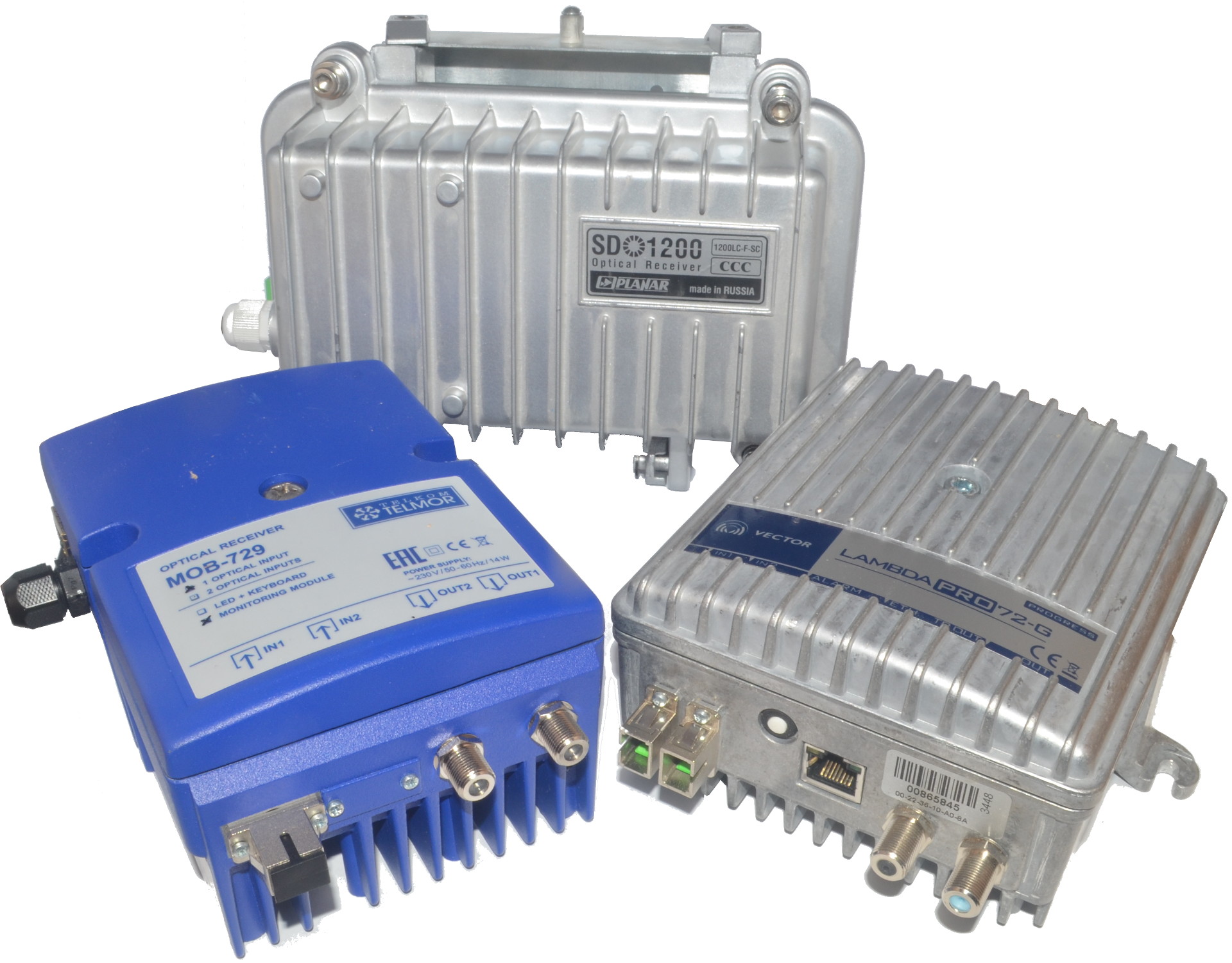
Optical receivers used in our network.
Depending on the architecture of the houses (number of floors, number of buildings and front doors, etc.), the optical receiver can stand at the beginning of each tower, or maybe one for several (sometimes even coaxial cable is laid between buildings) In the event of unavoidable attenuation on dividers and highways, they are compensated by amplifiers. Such as this, for example:
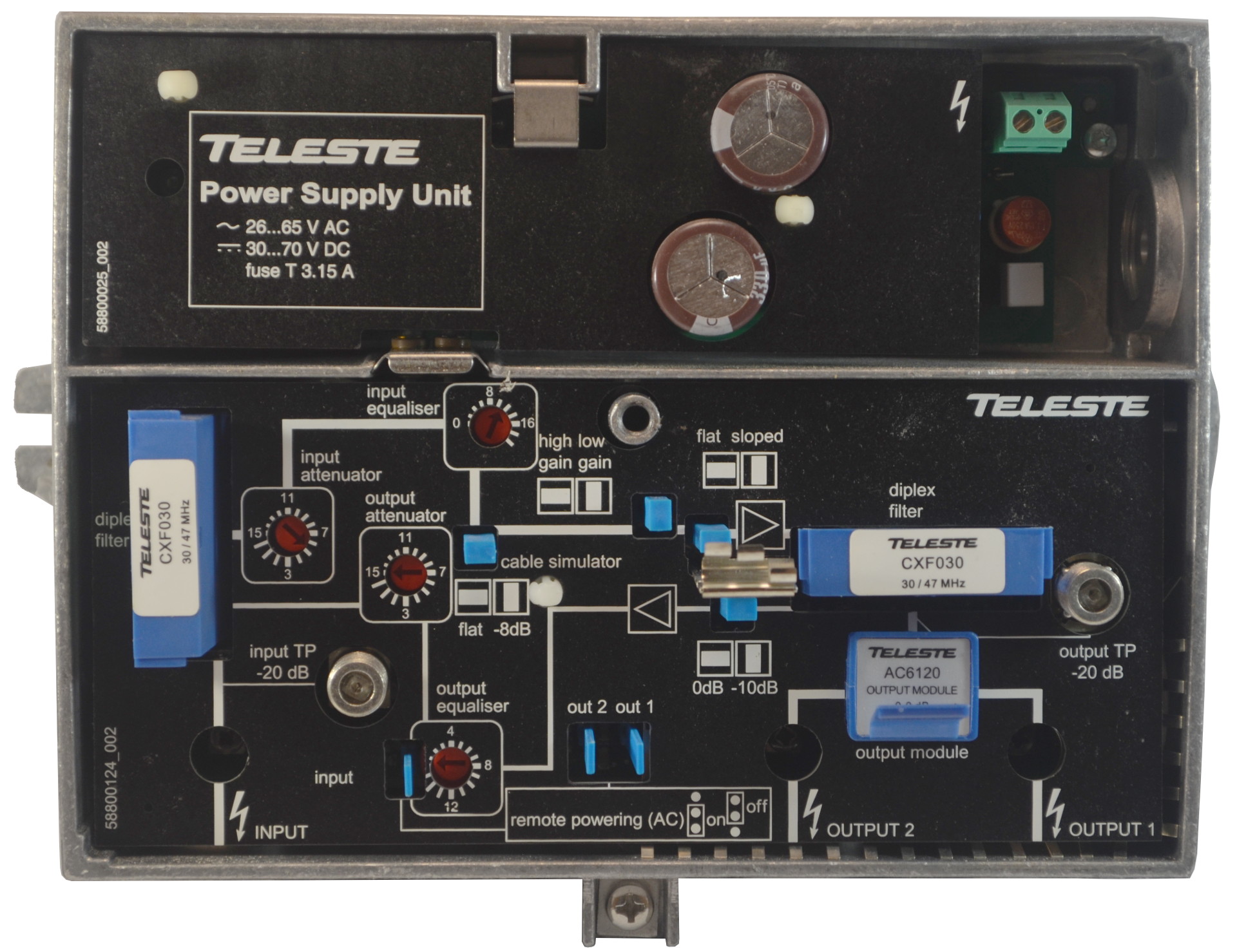
Amplifier of a signal KTV Teleste CXE180RF
Subscriber distribution network is built on a different type of coaxial cable and various dividers, which you can see in the low-voltage dashboard on your staircase
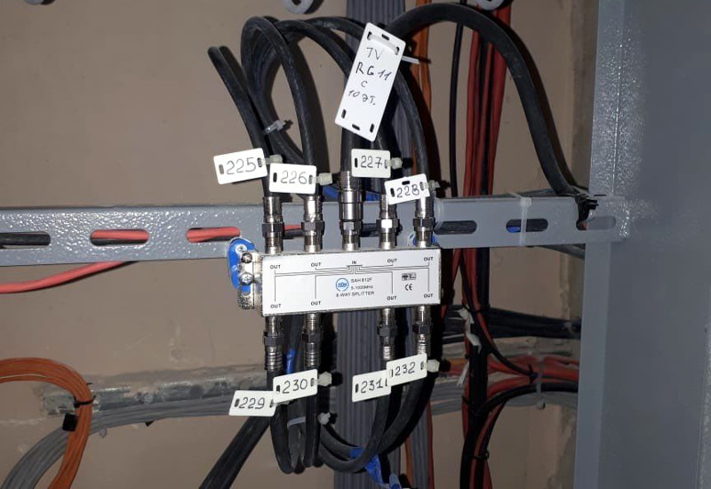
The outputs of subscriber splitters connect cables entering the apartment.
Of course, in most cases there are several TVs in each apartment and they are connected via additional splitters, which also contribute to attenuation. Therefore, in some cases (when there are many televisions in a large apartment) it is necessary to install additional signal amplifiers in the apartment, which for these purposes are smaller and weaker than the main ones.
Source: https://habr.com/ru/post/449322/
All Articles