How 3D scanning solves quality control tasks in production
Interview with an expert on 3D-technologies Georgy Kazakevich
- In the first part of the interview, we talked about reverse engineering. Now let's understand what is the control of geometry?
')
Geometry control is essentially quality control. Look here: the company receives the workpiece, which it must be finalized. If you make input control of these blanks, you can greatly reduce your headache at the manufacturing stage.
The cycle of processing and casting is a week, on the casting it is necessary to make holes, process planes and so on. Any casting has allowances, i.e. material that is removed from the workpiece during processing on the machine. Imagine that we process 100 elements, and it turns out that the 95th element lacks the allowance. We have already made 94, spent the time of the operator, electricity, worn out the cutting tool, and the whole party goes into marriage. This happens if there is no input control blanks.
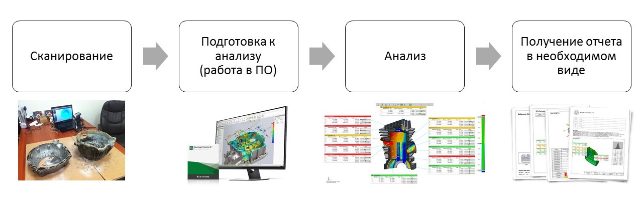
Fig. 1. Geometry control process using 3D scanning
- What does 3D-scanning give us in comparison with traditional methods of control?
- The bottom line is that the software allows the above process to loop. Suppose we have a series of identical parts in the amount of one thousand pieces. What needs to be done to conduct control with standard tools - templates, micrometers, calipers, etc.? We measure each of these thousands of details according to the list and draw up a table for each one. Now let's see how 3D scanning helps us.
Take a look at the diagram (Fig. 1): for the first part, the first three points are done manually (scanning, preparation for analysis and analysis directly), and the report is for you the software. For the next 999 parts, only the scan is done manually, the remaining three steps are performed by the software. Thus, you spend time only on digitization. And when controlling geometry, scanning is usually from 5 to 15% of the time spent, not more. Consequently, with flow control or mass production control, we begin to save a lot of time.
Previously, the company could afford to control one part out of a thousand, because it took a day. By implementing a 3D scan, you can control a hundred parts out of a thousand in just two days. On the first day we do everything manually, and we will spend only one more day on 99 parts - they only need to be scanned. Then we put the CAD-model in a certain folder and say to the software: “Work”.

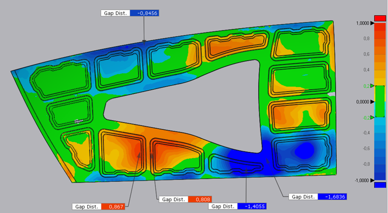
Fig. 2. Map of deviations of lining geometry
- Please tell us how it works using examples from iQB Technologies.
- There was a task to measure the thickness of the lining, successfully performed by the chief technical expert of our company, Alexey Chekhovich. There is a node for mixing liquids, it is metallic, because liquids are supplied under pressure. The problem is that properly processing the metal inside is, firstly, difficult, and secondly, expensive. In addition, metal is a material that interacts with many liquids, it can rust, corrode, etc. This node is covered from the inside with a special plastic compound. In order to achieve proper mixing of liquids, the coating must be uniform. If there are potholes in it, if it is uneven in thickness, turbulence will appear inside. They create additional pressure on the node, therefore, reduce its service life.
Previously, the company controlled one part out of a thousand, because it took a day. By implementing a 3D scan, you can control a hundred parts out of a thousand in just two days.
So, first a 3D scan of an uncoated unit was performed, then with a coating, and the results were compared. The red zone on the scan (fig. 2) is the cover. On the right picture you can see that it is uneven. Based on the results obtained, the customer may submit a claim to a subcontractor who deals with the application of this coating.

Fig. 3. Control of welded structure
The next example is the inspection of a welded structure performed by me. I traveled to Nizhny Novgorod to the plant of the company Liebherr, which produces metal structures for the assembly of industrial equipment. The metal sheets themselves come from Germany, they are welded in Russia and then sent back. Due to the fact that the design is quite large (2 m long), mounting holes are provided for attachment to other structures. If some kind of skew occurs during welding, the part will join in one place and not in the other. To avoid this, the factory decided before sending to Germany all the details of pre-scan and evaluate the deviations that were obtained during welding. In the table on the right (Fig. 3), we see the actual dimensions shown by the 3D scan. Deviations are displayed as a color map. Green is a good result, yellow is within tolerance, red is unacceptable deviation. Specifically, the part that we scanned, of course, does not pass and is considered a marriage.
- In what other industries did you use 3D-scanner and software to control geometry?

Fig. 4. Control of the geometry of the wing of the car
- For example, we had projects related to the automotive industry . Spare parts for cars, as you know, are quite expensive. They can always be ordered from China, but it is much more convenient to set up production in Russia. Our customer, who manufactures spare parts for high-end machines, began to receive complaints: the parts “play” when they are being put into place. We scanned the wing for BMW, made in Russia, and the wing of the original BMW. They compared them with each other and saw that the Russian part was slightly larger than required. Based on this, changes were made to the production cycle.
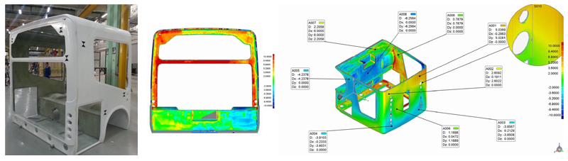
Fig. 5. Bus body
In Figure 6 you can see the body of the bus and the results of the 3D scan - this is a project that Alexey Chekhovich was involved in. In Moscow, there is a company that produces resin buses. Modern resins in strength can compete with metals, while they are much easier, and therefore more economical in terms of fuel consumption. This bus is going from several parts. The company noticed that during assembly some distortions and stresses arise. At the beginning, we were invited to shoot the made blanks. We filmed them and saw that the workpiece itself was a curve. Later we found out that the problem is not even in the blank, but in the form in which it was made. That is, the blank with the form perfectly matched, but the form itself was defective, and it had to be replaced. After that, it was decided that we would check the form about once every six months.
- Quality control includes operational control. Did you have to solve such problems using 3D scanning?
Yes, and this is usually associated with complex, expensive devices, such as an airplane . During operation, it is under enormous pressure, and there are restrictions on structural changes in the design that the aircraft acquires during operation. S7 has ordered a full Airbus 3D scan from us. We did not perform the analysis, as this data constitutes a commercial secret.

Fig. 6. Operational control of S7's Airbus
Pay attention to the scan, where you can see the sticker on the tail section (Fig. 6). The fact is that even such a thing as a sticker affects fuel consumption. The measuring systems that are at our disposal are so sensitive that they can calculate the optimal placement of the sticker. And at the request of the S7, a 3D scan of the tail of the aircraft was made with and without a sticker in order to understand how correctly it is located.

Fig. 7. Tooling control at an aircraft factory
I will mention one more project in the field of aviation. The customer of iQB Technologies was an aircraft factory, which initially commissioned us to analyze sheet products of rather large size (2 meters or more). Based on the measurements, we found out that the part is bent and does not fit into the required tolerances. And this is despite the fact that she passed the control at the plant itself.
After the part has been manufactured, it is placed on a wooden template (Fig. 9). If she lies flat, they conclude that she is fit. Since the 3D scanner showed deviations, we suggested checking the pattern. And here on the scan you can see a lot of zones with deviations. Such templates of large sizes, for which parts or parts are made, have a complex profile, and therefore they are difficult to control. The unprofitability of the template construction itself is, in fact, a big problem for many enterprises.
“And here a 3D scanner comes to the rescue ...”
- 3D-scanner in this case is an ideal device when it is necessary to measure products with a complex surface and large in size. This is the best solution for the production, which I described above.
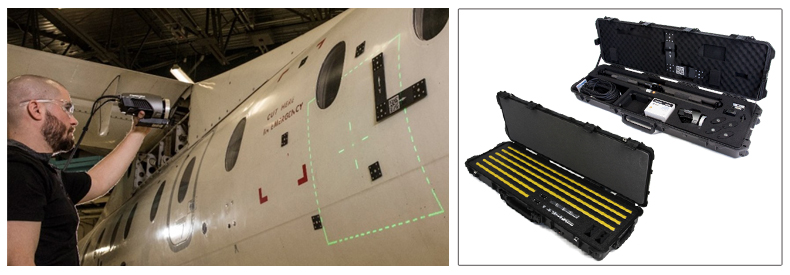
Fig. 8. Scanners in conjunction with the MaxSHOT Next photogrammetric system from Creaform are effectively used in aircraft and shipbuilding.
Since we are talking about 3D scanners, it is impossible not to mention such a topic as photogrammetry . This is a science that is engaged in determining the characteristics of objects, including the measurement of dimensions, from photographs. Each scanner is a kind of camera without zoom. You can shoot them objects that are either close or far away. That is, for example, either mountains, or someone's portrait. Because it is very important to know the exact distance between the cameras and the angle of convergence of the cameras in order to calculate the geometry. So, special devices were created that are called so-called photogrammetry devices. First of all, these are simply cameras that are completed with a set of lines (Fig. 8). The dimensions of these rulers with very high accuracy are measured by the coordinate measuring machine.
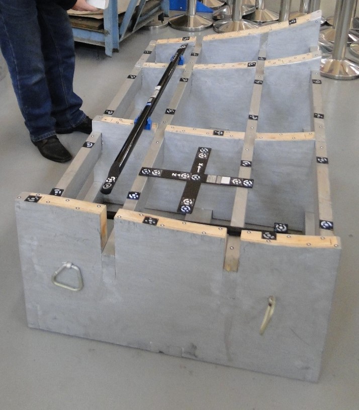
Fig. 9. Inspection of sheet metal parts.
So, you have a certain large object and there is a scanner, which is designed for shooting objects the size of a meter. Almost all scanners have a positioning system, i.e. they somehow determine their position in space relative to the object. Most often, the positioning system looks like a small round black-and-white label, which is pasted on the part (Fig. 7 right). If the part is large enough - obviously more than a meter, and we cannot scan it, then we additionally place a ruler and large square marks on this part, but at the same time we see that there are small round marks on the part. With the help of photogrammetry, we take a lot of pictures of the object from different angles. The more pictures, the better. Then the photogrammetry software recognizes large marks and a ruler, and using this ruler finds the distance between all the big marks — each of them is assigned a coordinate.
After that, small marks are recognized, coordinates are also assigned to relatively large ones, and large marks are deleted (Fig. 9). So simply, with the help of a camera and software, you get the exact coordinates of each of these small marks. They are recorded in a separate file that is loaded into the scanner software. Thus, a small 3D-scanner, which is guided by already known labels, you can scan parts or objects up to 20-30 meters in size. With such a simple and effective solution, geometry control problems are solved in many industries, including the aerospace industry and shipbuilding .
IQB Technologies invites you to the Metalworking-2019 exhibition at Expocentre Fairgrounds! We will present unique 3D solutions at our booth in Pavilion 5.1, and also hold a practical conference with a demonstration of 3D scanning and modeling (May 29, from 11:00 to 14:00). Details and registration for the conference link .
Source: https://habr.com/ru/post/449290/
All Articles