Test drive nanoCAD SPDS Construction site 8. Part 1
Test drive nanoCAD SPDS Construction site 8
We are starting to publish a test drive on the nanoCAD SPDS Construction Site. In the first part of the test drive, we will analyze the work with a special tool Project Manager, its main functions and ways of building elements of the construction genplan. In the second part of the test drive, we will consider the construction of roads and the selection of equipment.

Topic 1. Working with the Project Manager
1.1. Adding a new job
1.2. Adding new work from the classifier HESN
1.3. Assignment of bound pricing and resources to work
1.4. Appointment of construction equipment to work
1.5. Assigning material to work
1.6. Export project in the estimate program
1.7. Generation of bill of quantities
1.8. Generation of the list of machines and mechanisms
1.9. Generation of work schedule
1.10.Generation of the schedule of the need for machines and mechanisms
1.11. Generation of the schedule of staffing needs
1.12. Generation of the explanatory note
')
Theme 2. Design of the construction plan
2.1. Construction site
2.2. The contour of the building being constructed
2.3. Household Identifier
2.4. Temporary buildings of the town
2.5. Explication of temporary buildings
2.6. Water network
2.7. Construction site fencing
2.8. Safety signs
Topic 1. Working with the Project Manager
In this topic we will discuss the work with a special tool nanoCAD SPDS Construction Site - Project Manager and consider its main functions. The manager is designed to create a hierarchy of work, assignment of volumes and dates, as well as rates and resources for them. According to the compiled work, you can get a number of output documents.
To work, you will need the files "\ Topic 1_ Project Manager \ Task \ Project Manager.dwg" and "Project Manager.xml" located in the same directory. When you open a drawing file, the project file is loaded automatically. To start the exercise, open the “Project manager.dwg” file in nanoCAD Construction Site.
1.1. Adding a new job
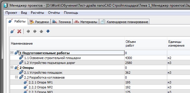
Call the Project Manager through the menu “Construction Site - Project Manager”. The project associated with this drawing file is automatically loaded and will be displayed in the Manager. On the "Works" tab, click the "Add Job" button.
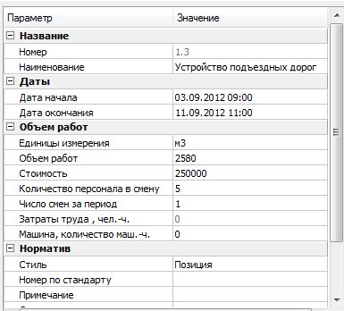
For new work in the right part of the dialog, enter the values shown in the figure.
New job takes its position in the structure of work according to the position of the cursor at the time of its creation. To move work to the desired location, use the buttons to move work.
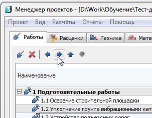
Move the job to section 3 “Span structures” to position 3.6.
1.2. Adding new work from the classifier HESN
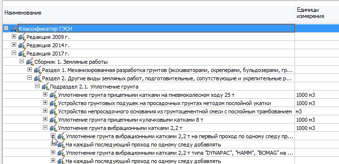
Now we add the work is not arbitrary, but from the classifier HESN. In the section of classifiers we will open the GESN classifier, we will deploy the 2017 edition, then “Part 1. Earthworks” - “Section 2. Other types of earthworks, preparatory, accompanying and fortifying” - “Subsection 2.1. Soil compaction ”-“ Soil compaction with 2.2 t vibratory rollers ”.
Place the cursor on this position and drag the job to 1 section “Preparatory work”. If necessary, use the work movement buttons to set it to position 1.2.
After that, set the unit of measure - "m3" and the volume equal to 450 m3.
1.3. Assignment of bound pricing and resources to work
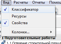
Switch to the “Pricing” tab of the Project Manager. Place the cursor on the added job “1.2. Soil compaction using 2.2 t vibration rollers. ” Make sure you have the classifier display enabled. To do this, in the "View" menu, check the appropriate settings.
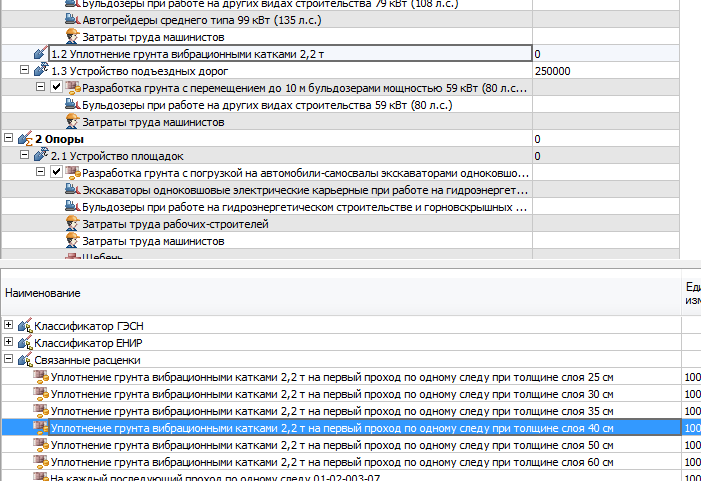
In the classifier section at the bottom of the window, the “Related quotations” section appears, if there are any for this work. Open this section and select the quotation “Soil compaction with 2.2 t vibratory rollers per first pass in one track at a layer thickness of 40 cm”. Holding the given price with the left mouse button, drag it to work “1.2. Soil compaction using 2.2 t vibration rollers. ”
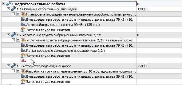
Pricing should appear with assigned resources under the specified work.
1.4. Appointment of construction equipment to work
Switch to the "Technology" tab. Place the cursor on the job “1.2. Soil compaction using 2.2 t vibration rollers. ” In the lower part of the window, select the category “Waste Technique”.
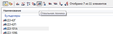
In this example, randomly select a bulldozer from the list and drag it to the right side of the dialog. A bulldozer will be assigned to work.

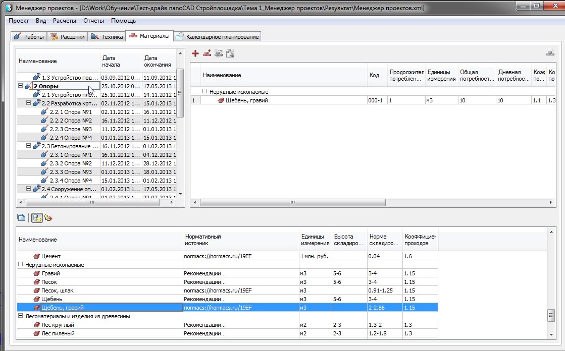
1.5. Assigning material to work
To assign materials to the selected work, switch to the technique tab. In the list of works, select the work “2.Opory”, in the classifier below select the required material “Crushed stone, gravel” and drag it to work. It will appear in the list of materials on the right with the parameters already entered, except for the duration and values of the need for the material.
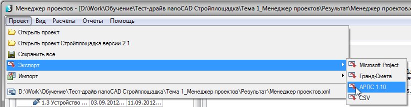
1.6. Export project in the estimate program
Works and information assigned to them can be downloaded for transfer to estimated programs. There is a separate download for the Grand Estimates program and to the universal data exchange format for estimated programs - ARPS.
To upload to the ARPS format, go to the Project-Export-ARPS 1.10 Manager dialog menu.
Save the file to your hard drive. Similarly, you can do unloading for the Grand Estimates.
1.7. Generation of bill of quantities
Switch to the “Works” tab and select all works with the Ctrl + A keys.
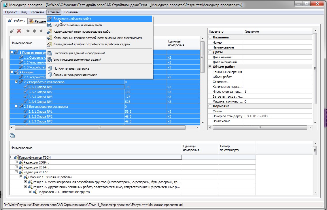
Next, run the "Reports - Bill of Work" command and place the table in the drawing. You can also get a statement of only the marked sections and work included in their composition.
1.8. Generation of the list of machines and mechanisms
Similarly, select all the work and run the command "Reports - Sheet of machines and mechanisms." Place the table in the drawing.
1.9. Generation of work schedule
Select all works with the Ctrl + A keys. Run the “Reports on the production schedule” command. In the settings dialog, set the time from 03/09/2012 to 07/28/2014. Select a grouping by months, filling - fill.
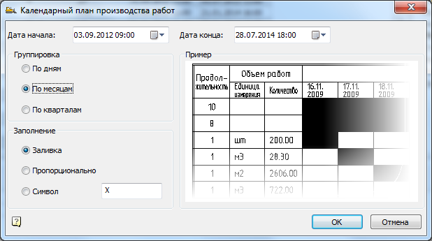
Place the received plan on the drawing.
1.10. Generation of the schedule of the demand for machines and mechanisms
The schedule can be obtained by analogy with the previous schedule.
1.11. Generating a workforce requirements schedule
Select all works with the Ctrl + A keys. Run the "Reports - Workforce Needs Schedule" command. Set the dates from 09/03/2012 to 07/28/2014 in the time settings dialog. Wait for the generation of the schedule and place it on the drawing. Set the schedule of labor movement below.
1.12. Explanatory note generation
Run the "Reports - Explanatory Note" command. Save the * .doc file to your hard drive, it will automatically open after that.
Theme 2. Design of the construction plan
In this topic, we will look at how to build the elements of the construction plan in the nanoCAD SPDS Construction Site .
To work, you will need the file "\ Subject 2_Ogeneration of the CST \ Task \ CST. Dwg". In the course of carrying out the exercises of this topic, we will launch all the commands from the main menu section “Construction Site-Stroygenplan”, therefore, further teams will be written in abbreviated form, without specifying this part of the path. To start the exercise, open the “SGP.dwg” file in the nanoCAD SPDS Construction Site.
2.1. Construction site
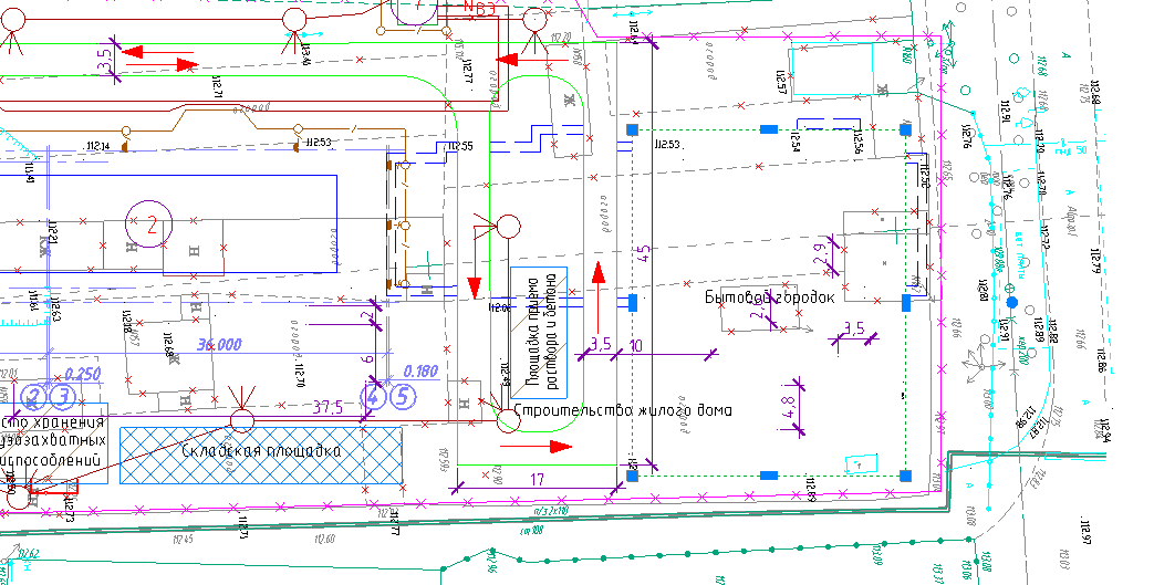
From the menu “Construction Sites”, run the command to build a construction site. This element serves as a conditional identifier for the construction site so that subsequent designations can be assigned to a specific site on the plan. In the dialog, select the “Construction Site” icon. In the properties, specify the name of the site - "Construction of a residential house", put the serial number - "1".
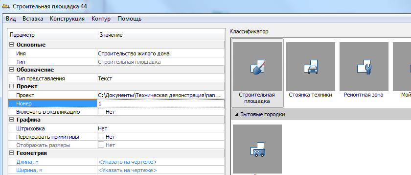
Further on the drawing conditionally indicate the boundaries of the site. This contour has nothing to do with real boundaries, since the object itself serves only as an identifier for other construction site objects. In the command options, select a rectangle and specify two diagonal points around the existing drawing objects. The conditional border area by default is indicated in blue.
2.2. The contour of the building being constructed
Build the contour of the building being constructed. To do this, run the command "Buildings - Erected Building." By default, the cursor in the classifier indicates the type of buildings we need. In the dialog, specify the name of the building - “Building being erected” and give it a serial number “2”.

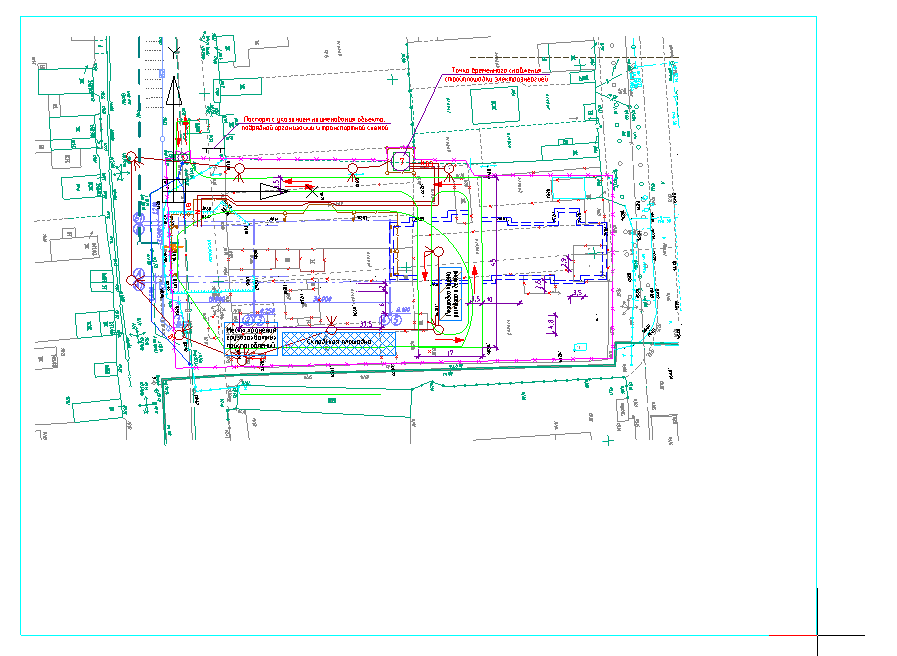
For ease of operation, select the option of building a rectangle in the command options. Specify the outline of the building as shown.
In this case, the dimensions of the building are indicated by us approximately, but in a real project everything is indicated exactly in size using various methods of construction.
2.3. Household Identifier
The identifier of a domestic town plays a similar role as a site identifier. It serves to determine whether the temporary buildings of a town belong to a particular town, since there may be several of them in the drawing. To add a household town, run the command “Household town-Household town”. In the dialogue, select the pictograph of a household campus, give the town a name - “Domestic Town”, the sequence number “3”. Please note that the specified town to the construction site. In our case, it is one, so it is not necessary to change this parameter. For simplicity, select the method of constructing a rectangle and indicate the diagonal points on the drawing.
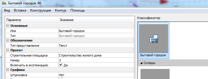
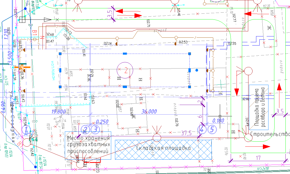
In our case, the boundaries of the domestic town are determined by us arbitrarily, as shown in the figure.
2.4. Temporary buildings of the town
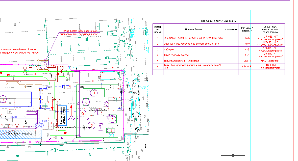
For a domestic town defined by us, it is now necessary to affix temporary buildings. Run the command "Household Town - Temporary Building." In the classifier, you can search by name. Choose "Sanitary-sanitary complex on 36 places (male)". When you set the cursor, the name is transferred to the properties automatically. Please note that the building belongs to a previously defined household town. Be sure to check the inclusion box.
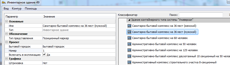
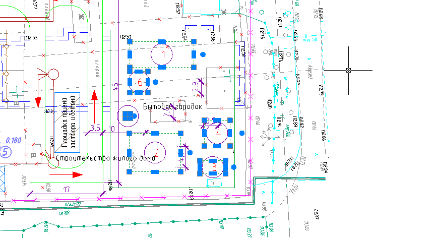
Set for it the sequence number "1" and place on the drawing within the boundaries of the town. Similarly, place other buildings, each time assigning the following sequence number:
- Dining-dispensing for 36 seats;
- First-aid post;
- Construction headquarters;
- Toilet cabin "Standard";
- Transformer substation power up to 630 kW.
- In the picture you can see the buildings of a domestic town with markers.
2.5. Explication of temporary buildings
Launch the Project Manager via the main menu of the program. In the Manager menu, call the construction of the explication through the menu "Reports - Explication of temporary buildings."
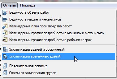
In the site selection dialog, select "Household town".
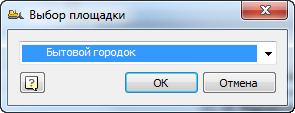
Place the explication in the drawing as shown in the figure.
2.6. Water network
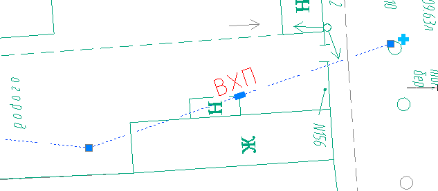
We put down the designation of the external engineering network on the plan. Run the command “Networks - VK - Water supply”. In the dialogue, select the icon "Temporary network of domestic water supply." Pay attention to belonging to the construction site.
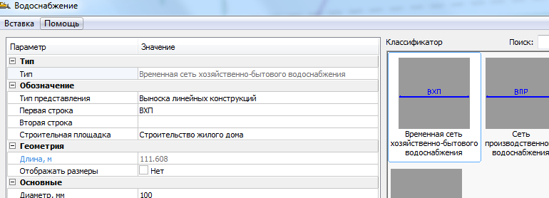
Build an arbitrary polyline on the plan. Select the line with the cursor. Next to the first specified point, a special marker in the form of a cross will be visible. Click on this marker and build along a line several wells.
2.7. Construction site fencing
Call the command "Fencing - Fencing". You can choose arbitrarily the type of fence and give it a name in the properties of the first and second line. Put a broken fence line around the construction site on the plan. Use the snapping option when setting the last segment. On the constructed line, click the special marker in the form of a cross and put down the gate mark along the fence.
2.8. Safety signs
Commands for installing safety signs are invoked through the main menu of the program “Construction Site - Signs - Safety Sign GOST 12.4.026”. You can search for the desired character by name. You can collect characters in a set and install them as a group in one command. In this case, select the signs and install them one by one. In this exercise, choose the signs arbitrarily. To do this, find the desired character and double-click on it, place it in the "Selected characters" section at the top of the dialog.
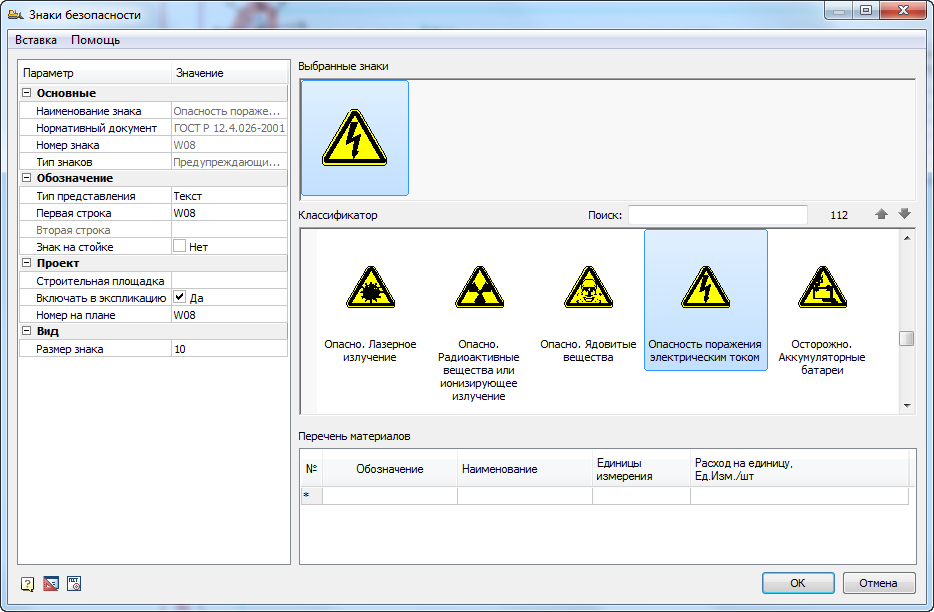
After that, click "OK" and place the mark on the drawing. Repeat the operation for multiple characters.
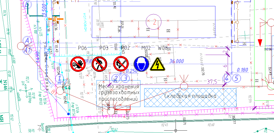
Run the Construction Site - Reports - Safety Signs Specification command. Set the specification at the bottom of the drawing. The specification is interactive. You can, for example, delete one of the characters, and it will automatically be updated.
Records of past webinars you can view on our YouTube channel .
More information on spds.club
Olga Artemyeva, Head of Software Development Department

Source: https://habr.com/ru/post/449166/
All Articles