Test drive nanoCAD SPDS Metal structures 1.2. Part 2
Test drive nanoCAD SPDS Metal structures 1.2 Part 2
We continue to publish a test drive on nanoCAD SPDS Metal structures. In the first part of the test drive, we began to build a production framework. In the second part, we will look at how to create vertical links, struts, runs and place them on the plan, as well as create a cross-section.

Chapter 6. Creating vertical links and placing them on the plan
6.1. On the Metal Toolbar, we call the Beam command, then in the dialog window that appears, set the necessary parameters.

')
6.2. In the dialog, set the necessary parameters for the beam:
- Choose a square pipe profile according to GOST 8639-82 standard size 100x5. C245 steel material.
- View from above".
- Display - "conditional".
- In the Geometry tab, leave unchanged (indicate on the drawing).
- The Offset Axis tab is left unchanged (the center of the section).
- The Rotate tab is left unchanged (“0” rotation).
- The Marking tab is left unchanged (callout of linear structures, position).
- In the Sheet Items tab, we tick Include in specification and Include in item list.
- Change the type of structural element by clicking on the Edit Types icon.

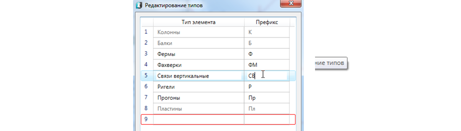
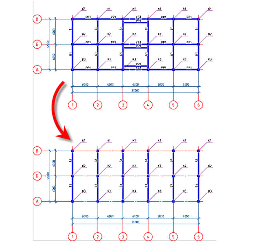
6.3. In the type editing dialog, we change the line: Element type - Vertical links, prefix - CB. After the change, click OK.
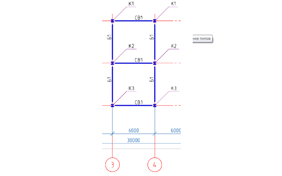
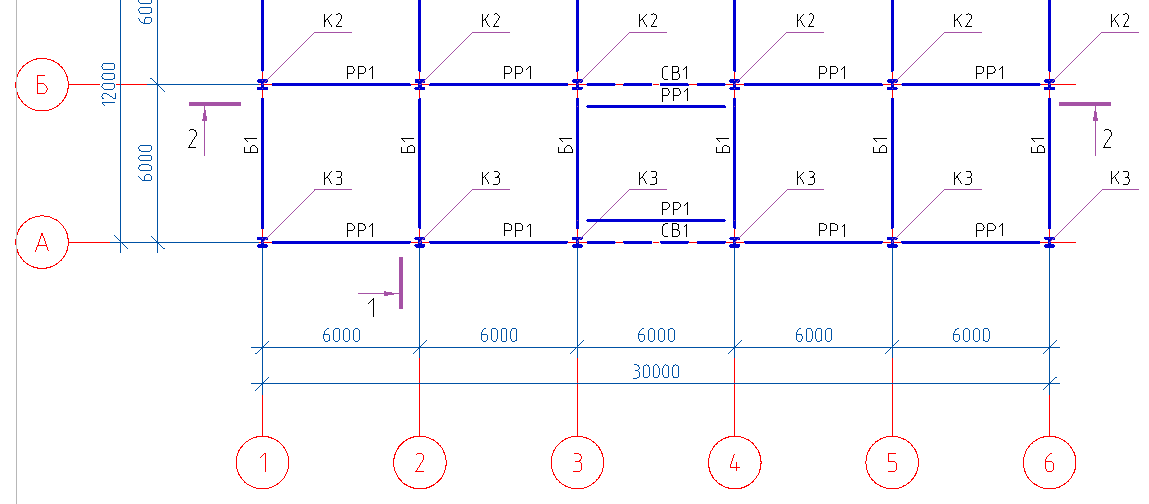
6.4. The dialog of the Beams window has changed to Vertical Connections, then click OK and arrange the connections between the axes "3-4".
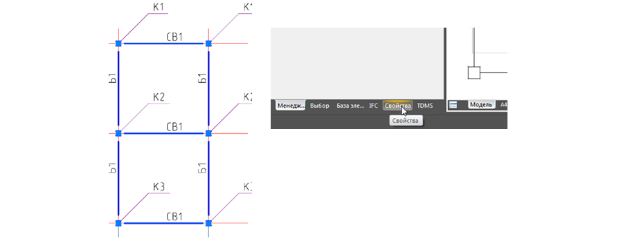
6.5. Select CB1 in the communication plan, then go to the Properties tab.
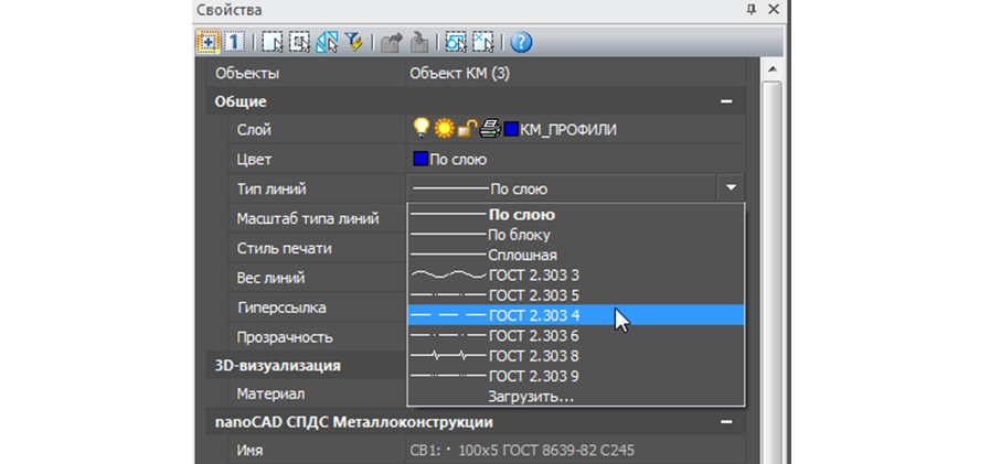
6.6. Properties window for CB1 links change the linetype to dashed.
Chapter 7. Creating spacers and placing them on the plan
7.1. Now you need to place the struts along the axis "A", "B", "C". To do this, call the Balka command again. In the dialog window that appears, the program has already saved the parameters we have previously entered (for CB1 links).
7.2. Change the type of structural element by clicking on the Edit Types icon
In the type editing dialog, we change the line: Element type - Spacers, Prefix - PP. After the change, click OK

7.3. The dialog window Connections vertical has changed to Struts, then click OK and arrange the struts along the letter axes.

Chapter 8. Creating runs and placing them on the plan
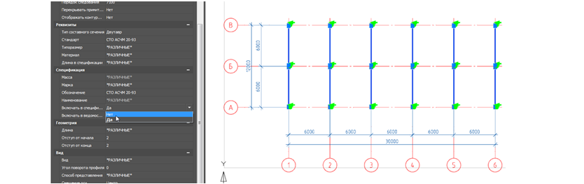
8.1. Create a separate plan for the placement of runs, for this we select a grid of axes with dimensions, columns, beams and copy them to a free space in the drawing model.
8.2. On the copied plan, select all the symbols, and then delete them with the Delete command.

8.3. After deleting the notation, we select all the columns and beams, then go to the Properties tab and for all selected elements change the Include attribute to the specification - None. This is done so that the same elements are not included in the specification two times.
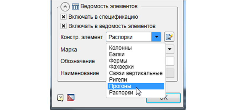
8.4. On the Metal Toolbar, we call the Beam command, then in the dialog window that appears, set the necessary parameters.
- Select the profile channel according to GOST 8240-97 standard size 24L. C245 steel material.
- View from above".
- Display - "conditional".
- In the Geometry tab, leave unchanged (indicate on the drawing).
- The Offset Axis tab is left unchanged (the center of the section).
- The Rotate tab is left unchanged (“0” rotation).
- The Marking tab is left unchanged (callout of linear structures, position).
- In the Sheet Items tab, we tick Include in specification and Include in item list.
- Change the type of structural element for Runs.
8.5. Having set all the parameters, click OK and arrange the runs between the digital axes with a step of 1500 mm.
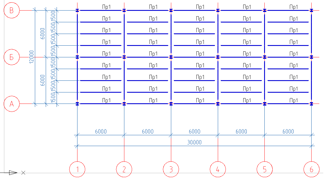
Attention! It is not necessary to insert structural elements alternately several times, you can insert one structural element, and then simply copy it.
Chapter 9. Creating a cross-section
9.1. On the toolbar SPDS call the command Cuts, sections.
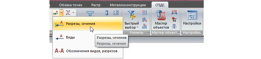
9.2. In the dialog box, specify the number - 1 and click OK.

9.3. Place the designation of the section "1-1" along the axis "2" on both plans.
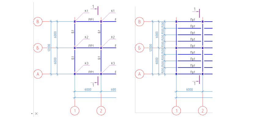
9.4. Place the designation of the section "2-2" along the axis "B" on both plans.
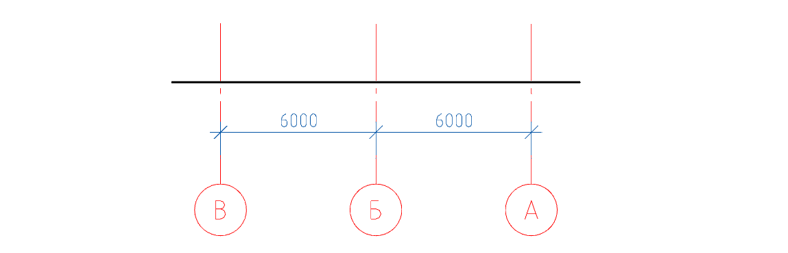
9.5. We proceed to the construction of the section 1-1. On the toolbar SPDS call the command Single axis, set the name of the axis "A" and tick the Dimension chain.

9.6. We place individual axes from right to left by specifying 6000 in the command line.

9.7. Perform the renaming of the axes.

9.8. On the section with the help of the Cut command, we will show the floor level.
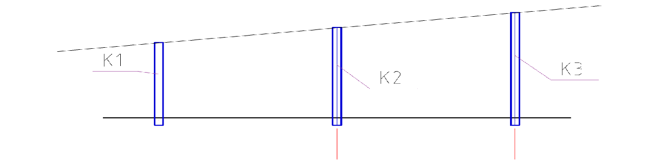
9.9. On the Metal Toolbar, we call the Column command, then in the dialog window that appears, set the necessary parameters
- In the Sheet of Elements tab, uncheck Include in specification and select the previously created brand of K1 from the list.

- Front view".
- The display is “full”.
- In the Geometry tab, set the base level to -300, and leave the ogolovka mark to 3000 by default (we will correct the ogolovka mark when building the section).
- The Offset Axis tab is left unchanged (the center of the section).
- The Rotate tab is left unchanged (“0” rotation).
- The marking tab is left unchanged (positional callout, position).
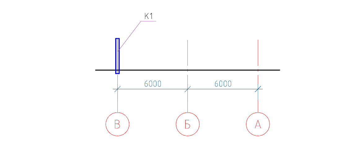
9.10. Having set all the parameters, click OK and place the column along the "B" axis.
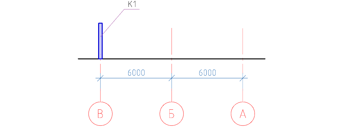
9.11. Move the column 300 mm down.
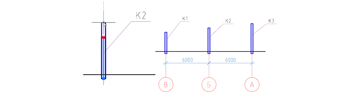
9.12. According to the description of the actions in paragraphs 9.9-9.11 we insert and displace columns K2, K3.
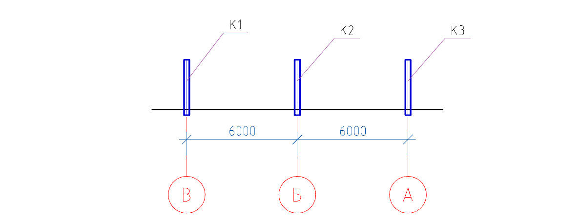
9.13. We will increase the length of the K2 column by 600 mm, K3 by 1200 mm using the stretch knobs.
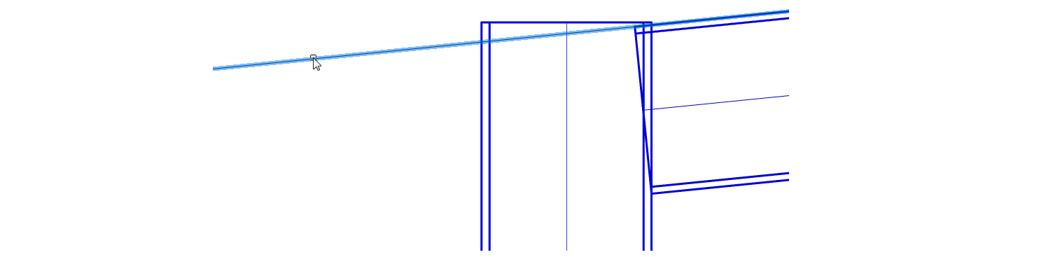
9.14. Using the Direct command, we will create a slope for the beams by connecting the upper right corner of the K1 and K3 columns.

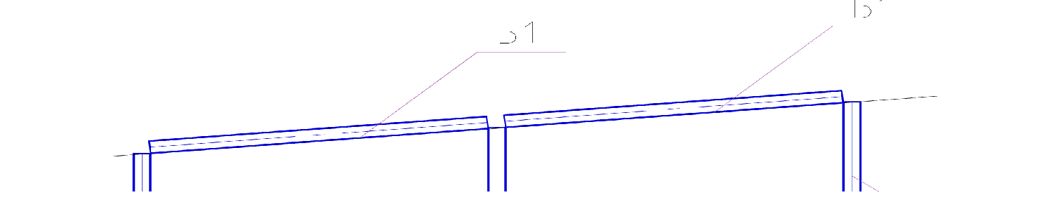
9.15. On the Metal Toolbar, we call the Beam command, then in the dialog window that appears, set the necessary parameters.
9.16. To begin with, in the upper part of the dialog you need to click on the Insert several icon, so that with several successive inserts into the drawing of this beam, its mark does not automatically change (the beam will be inserted with one mark).
- In the Sheet of Elements tab, we change the Type of the structural element to (beams).
- Select the previously created brand B1.
- Front view".
- The display is “full”.
- In the Geometry tab, leave unchanged (indicate on the drawing).
- The Offset Axes tab is set (bottom center).

- The Rotate tab is left unchanged (“0” rotation).
- The Marking tab is changed to (positional callout, position).
- In the Sheet Items tab, the Include in the specification checkbox should be unchecked.
9.17. Having set all the parameters, click OK and place the beams along the auxiliary line between the “B-B and B-A” axes.
9.18. Using the stretch knobs, extend the columns up 300 mm.
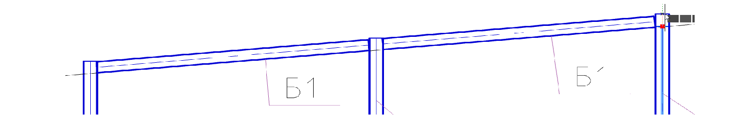
9.19. Move the auxiliary line to the top flange of the beam B1.
9.20. Perform the trimming of the top of the columns, for this we call the command Trimming profiles.

9.21. We specify the auxiliary line as the trimming contour.
9.22. Press Enter and specify the place to trim the top of the columns with the cursor. Pressing the left mouse button makes the trimming.

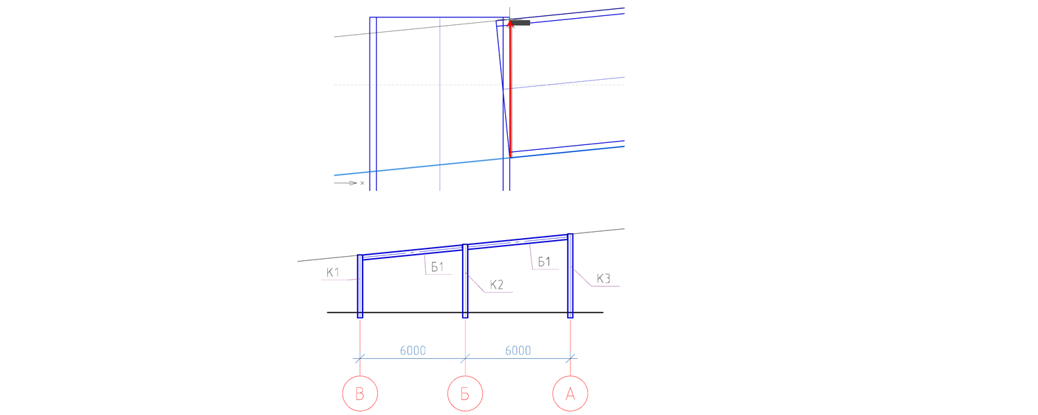
9.23. Create auxiliary lines (see Section 9.14) for trimming beams.
We will make auxiliary lines indented from the column edge by 30 mm.

9.24. Perform trimming beams B1, for this we call the command Trim profiles.
9.25 Let us specify the vertical auxiliary line as the contour of trimming.
9.26. Press Enter and specify the place to trim the beam with the cursor. Pressing the left mouse button makes the trimming.

9.27. After making the undercuts of the B1 beams, we remove the auxiliary lines.
9.28. We will show the runs in the section, for this we will call the Balka command, then in the dialog window that will appear we will set the necessary parameters.
- In the Sheet tab of the elements select the type of the structural element Runs.
- Select the previously created brand Pr1.
- View - "section". The main central axis - remove the check mark.
- The display is “full”.
- In the Geometry tab, leave unchanged (indicate on the drawing).
- In the Offset tab of the axes set (bottom left corner).

- In the Rotate tab, leave unchanged (turn "0").
- In the Marking tab we remove the designation (no).
- In the Sheet Items tab, the Include in the specification checkbox should be unchecked.
9.29. Having set all the parameters, click OK and place the run along the "B" axis.

9.30. Change the position of the girder using the turn knob.

9.31. Copy the run on the slope in increments of 1500 mm.
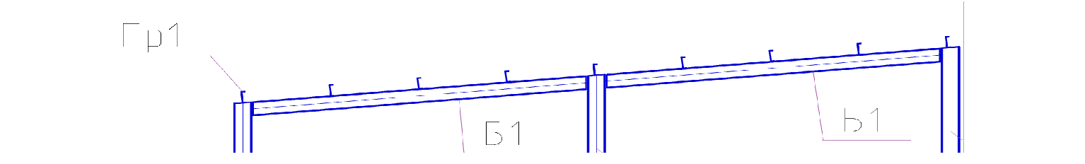
9.32. Using the SPDS tools, we will install the comb leader on the runs.

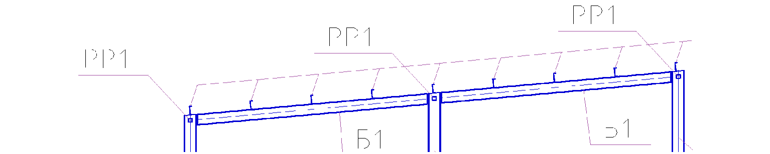
9.33. We will show on the cross section of the spacer, for this we will call the Beam command, then in the dialog window that will appear we will set the necessary parameters.
- In the Sheet tab of the elements select the type of structural element of the Spacer.
- Select the previously created brand PP1.
- View - "section". The main central axis - remove the check mark
- The display is “full”.
- In the Geometry tab, leave unchanged (indicate on the drawing).
- In the tab Offset axes set (center).
- In the Rotate tab, leave unchanged (turn "0").
- In the Marking tab we remove the designation (no).
- In the Sheet Items tab, the Include in the specification checkbox should be unchecked.
9.34. Having set all the parameters, click OK and place the struts along the axes "ABC". Spacers are placed 150 mm below the top of the columns.
9.35. Put the designation "1-1" for the section, for this we call the command Designations of types, sections

9.36. In the window that appears, enter the number "1-1", then click OK and place the designation on top of the drawing.

In the next part we will discuss how to create a longitudinal section.
We invite you to take part in the free webinar "Creating a metal farm in nanoCAD SPDS Metal".
The purpose of the webinar is to demonstrate to CAD users how the efficiency of the work of design engineers is increased when using specialized software nanoCAD DPS Metal structures. The participants of the webinar will get acquainted with the updated functionality of the program, will see two-way automatic communication between the project manager, the drawing and the specification. In the framework of the webinar, the tools of the nanoCAD software program, Metal Structures, which allow to design various elements of metal structures, will be considered. An example will be shown of how to use a parametric object to quickly design a truss metal truss and automatically generate a list of elements and a specification for rolled metal.
 Dmitry Gostev, Leading Engineer, Magma Computer
Source: https://habr.com/ru/post/448280/
All Articles