SMS monitoring of the weight of three hives for $ 35
Very little time has passed since the previous publication on the system for $ 30 .
What has changed over the past lunar month?
- Added solar battery - the time is almost unlimited.
- Added sending information on the call.
- Ability to work with all types of communication modules that have fallen into my field of vision - AiThinker, Goouu tech, SIM800 / 900, Neoway M590 *
But the most important thing is that the communication module and the microcontroller are now physically separated, which eliminates interference in its operation with the HX711.
And all this thanks to constructive criticism of habrovchan and beekeepers who have joined the discussion of the system.
The remaining TTX remain the same - the maximum weight of the hives is 200kg, after sunset a measurement is made, and the indicators are sent.
Anticipating criticism about the non-use of sleep modes and additional signal lines of GSM modules, I will say the following:
Each communication module has its own specifics - who falls asleep at a low signal level, who is at a high level, some - by double pressing.
The specifics of “do-it-yourself” implies some kind of creative part, which is exactly where it should be shown.
I did the same system with an eye on the further development of monitoring other parameters of the hive, where sleep is not really needed.
In general, in the title scheme - pure android basic system from which you can dance anywhere with the design and the number / set of sensors, modules, etc.
This same article is about weights, and under the cut is my personal vision and system performance.
One word - WELCOME! GO!
For a start, this system does not sleep ... at all, because a 6-volt two-battery solar battery, even in cloudy weather, produces 5 volts and up to one hundred milliamperes.
And the consumption of the entire system is 17mA, in standby mode (in GSM1800 standard) and about thirty on GSM900.
Besides, as already mentioned, this is done with an eye to implementing additional monitoring functions in real time (for example, a swarm can go out in 5 minutes) - there is no time to sleep ;-)
Want absolute energy saving, so it will be in the next publication, but it will be completely different story system.
* Yes, also about the footnote about communication modules - it's not that I become an adept of AiThinker, I just need to assemble Neoway myself, and SIM800L modules require a separate article on educational work with them.
In short, the selected GSM-ki - IMHO, the only ones that can work on 4 wires without additional dancing with tambourines, including power.
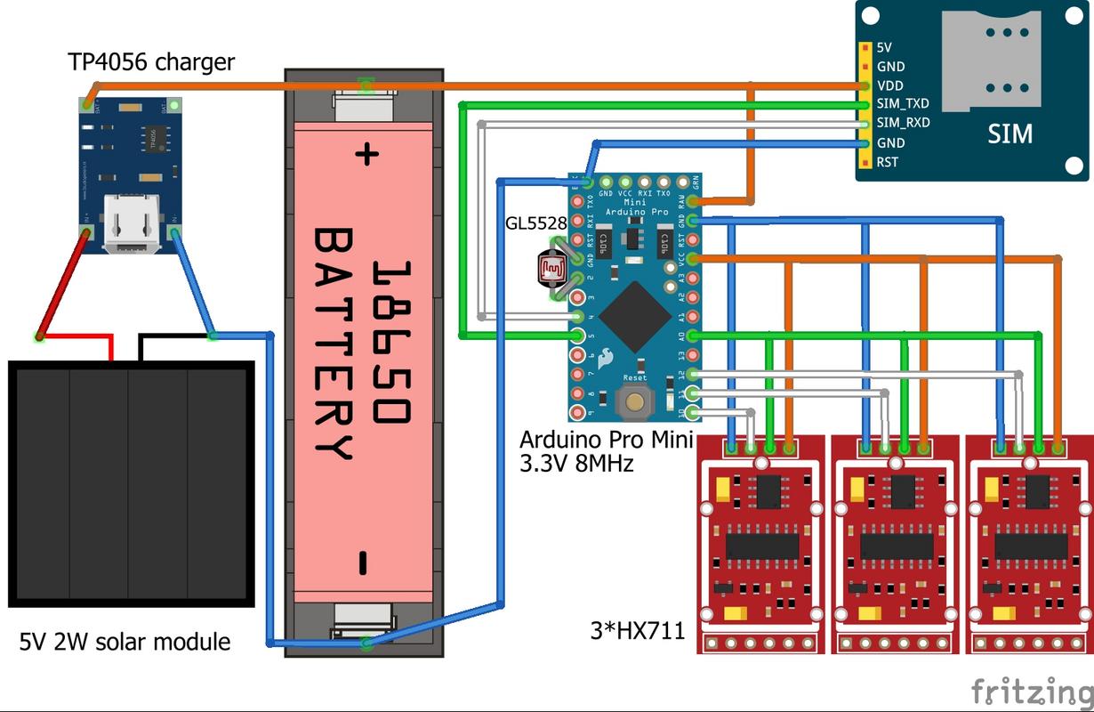
We will need the following set of equipment / materials:
- Arduino Pro Mini 3V
Attention should be paid to the linear converter chip - it should be exactly 3.3V - on the chip of the marking KB 33 / LB 33 / DE A10 - I got the Chinese confused and the whole batch
The boards in the store turned out to be 5 volt regulators and quartz at 16MHz. - USB-Ttl on the CH340 chip - you can even 5-volt, but then during the microcontroller's firmware, the Arduino will need to be disconnected from the GSM module in order not to burn the latter.
Boards on the PL2303 chip do not work under Windows 10. - GSM communication module Goouu Tech IOT GA-6-B or AI-THINKER A-6 Mini.
- GSM GPRS "YG-01" antenna
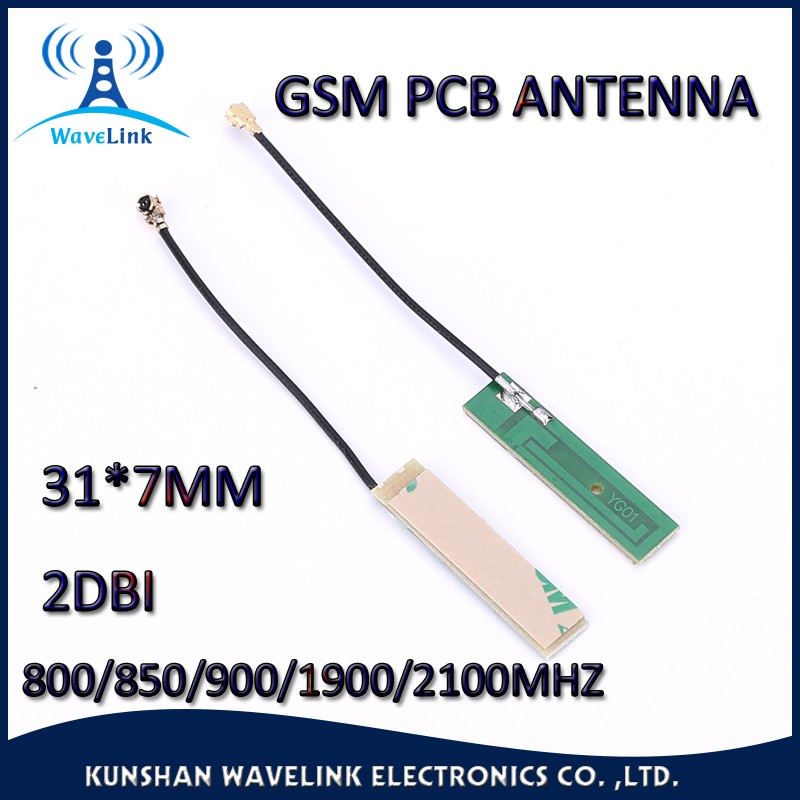
How they achieved such a gain is a mystery - it can be relatively complete lack of it ;-). - The starting package of the operator with good coverage in the location of your apiary.
Yes, the package must first be activated in a regular phone, DISABLE THE PIN REQUEST at the entrance, and replenish the account. - Dupont wire 20cm mother-mother - 4 pcs. (for connecting Arduino to USB-TTL)
- 3 pcs. HX711 - ADC for scales
- 6 strain gauges for weight up to 50kg
- 15 meters of 4-wire telephone cable - for connecting weight modules and GSM with ARDUINO.
- Photoresistor GL5528 (important is this, with a dark resistance of 1MΩ and a light resistance of 10-20 kΩ).
- two pairs of 6P6C plugs and sockets - telephone, sockets - with "tails"
- 50cm double-sided tape 10mm wide - for attaching the solar battery to the GSM-module body.
- TP4056 base battery charger for LiIon batteries
- Battery holder 18650 and, in fact, the battery itself.
- A bit of wax or paraffin (candle oil burner) - for moisture protection HX711
- A piece of wooden timber 25x50x300mm for the foundation of strain gauges.
- A dozen of self-tapping screws with a press washer of 4.2 × 19 mm for attaching the sensors to the base.
- Solar battery 5-6V 2W (there was no one in the next radio car - took two single-cell and a pair of 1N4148 diodes)
There is no reverse current through the charger, but parallel solar modules should be properly turned on through diodes - A box for a communication module and a solar battery (size 60x100mm) - you can take a suitable distribution box from electrical goods, I had a perfect plastic from business cards 30x60x100.
In addition, you will need uncured hands, soldering iron EPSN-25, rosin and solder POS-60.
For carpentry enough hacksaws for wood / metal, chisels and drills with a 3mm drill bit.
The system layout is as follows:

In any case, you should not have a GSM module closer than a meter from the Arduino - with a high signal power in the GSM900 standard, this may cause the microcontroller to reboot!
Well, the communication module with the solar battery - should be installed on the pole - and the reception will be better, and further from the bees.
Now proceed to the assembly:
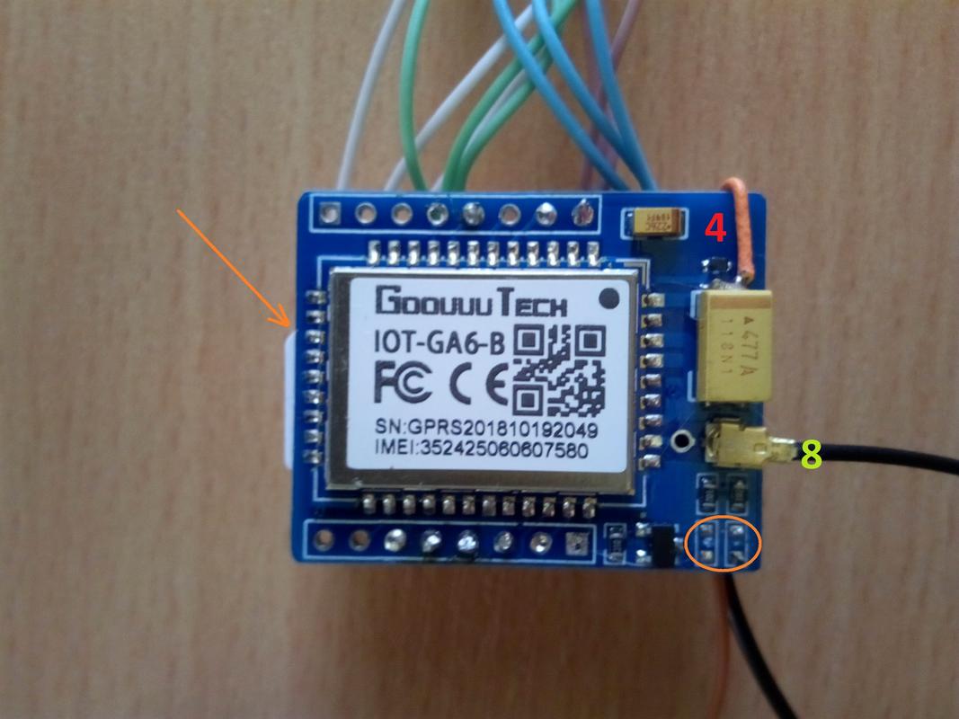
To begin with, we evaporate two LEDs from the GSM-module (the place where they were circled in an orange oval).
We insert the SIM card with the contact pads to the printed circuit board, the bevelled corner in the photo is indicated by the arrow.
Plus from the battery and the wire going to the controller it is soldered to the capacitor directly (4).
The fact is that the communication module itself requires 3.4–4.2V for its power supply, and its PWR contact is wired to a step-down downconverter, therefore, to operate from a li-ion voltage, it is necessary to bypass this part of the circuit.
Then we carry out a similar procedure with the LED on the Arduino board (the oval to the right of the square chip).
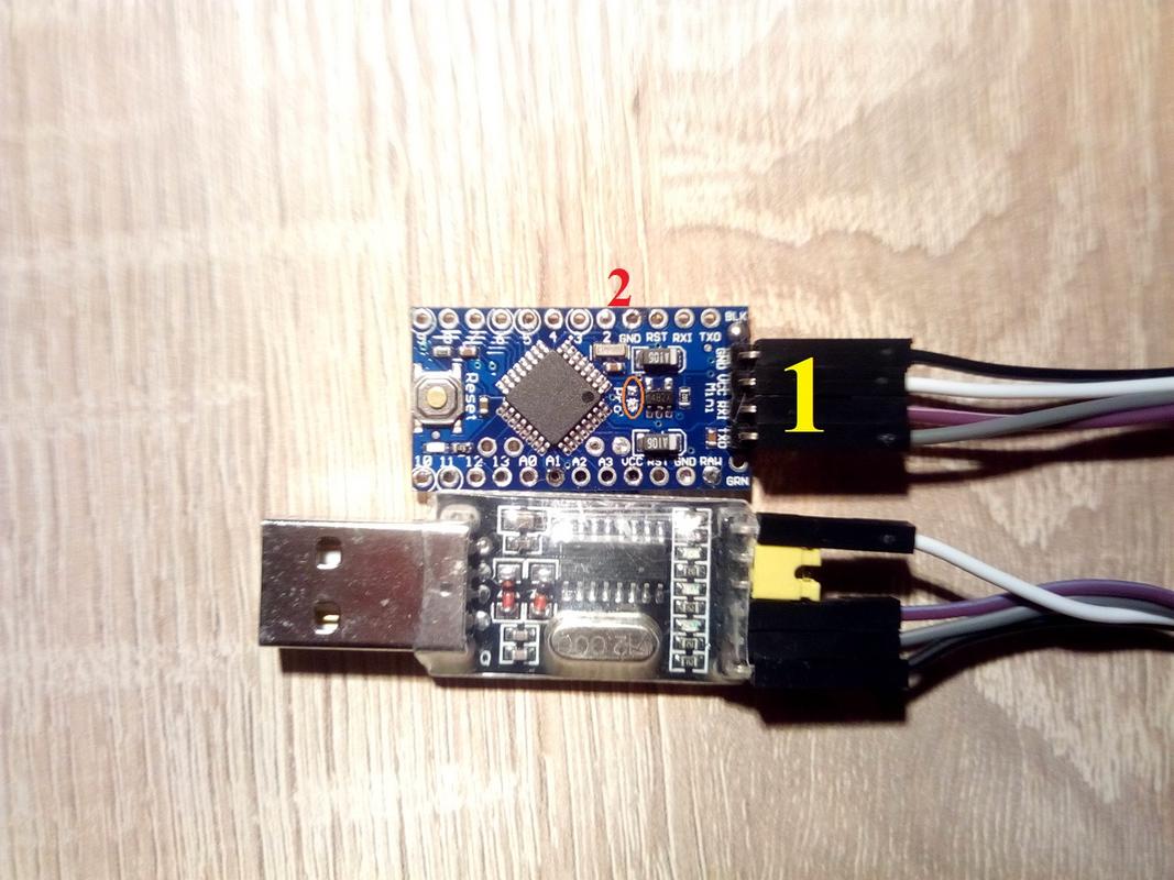
Solder the comb to the four pins (1), always horizontally - along the board.
The photoresistor shortens the legs to 10mm and solder it with 20 cm conductors to the GND and D2 terminals of the board (2).
We supply power through a linear converter - at low current consumption, the drop-out voltage drop is 0.1V.
On the other hand, by applying a stabilized voltage to the HX711 modules, we eliminate the need to modify them at a lower voltage (and, at the same time, from an increase in noise as a result of this operation).
Now you need to take 5 meters of a telephone four-wire cable, and unsolder between the microcontroller and the communication module according to the diagram at the beginning of the article (the colors of the wires correspond to reality).
We also solder the battery holder, everything else will be done a little later.
And now we will for some time digress from the soldering iron, and move on to the program part.
I will describe the sequence of actions for Windows:
First, you need to download and install / unzip the Arduino IDE program - the current version is 1.8.9, but I use 1.6.4
For simplicity, unpack the archive in the folder C: \ arduino- "number_Your_version", inside we will have the folder / dist, drivers, examples, hardware, java, lib, libraries, reference, tools, as well as the arduino executable file (among others).
Now we need a library to work with the HX711 ADC - green button "clone or download" - download ZIP.
Content (folder HX711-master) is placed in the directory C: \ arduino- "number_Your_version" \ libraries
Well, of course, the same driver for USB-TTL from the same github - from the unpacked archive, simply start the installer with the SETUP file.
For those who are reluctant to mess with libraries, I packed my build of the Arduino IDE program - just download and unpack it.
Run and configure the program C: \ arduino- "number_Your_version" \ arduino
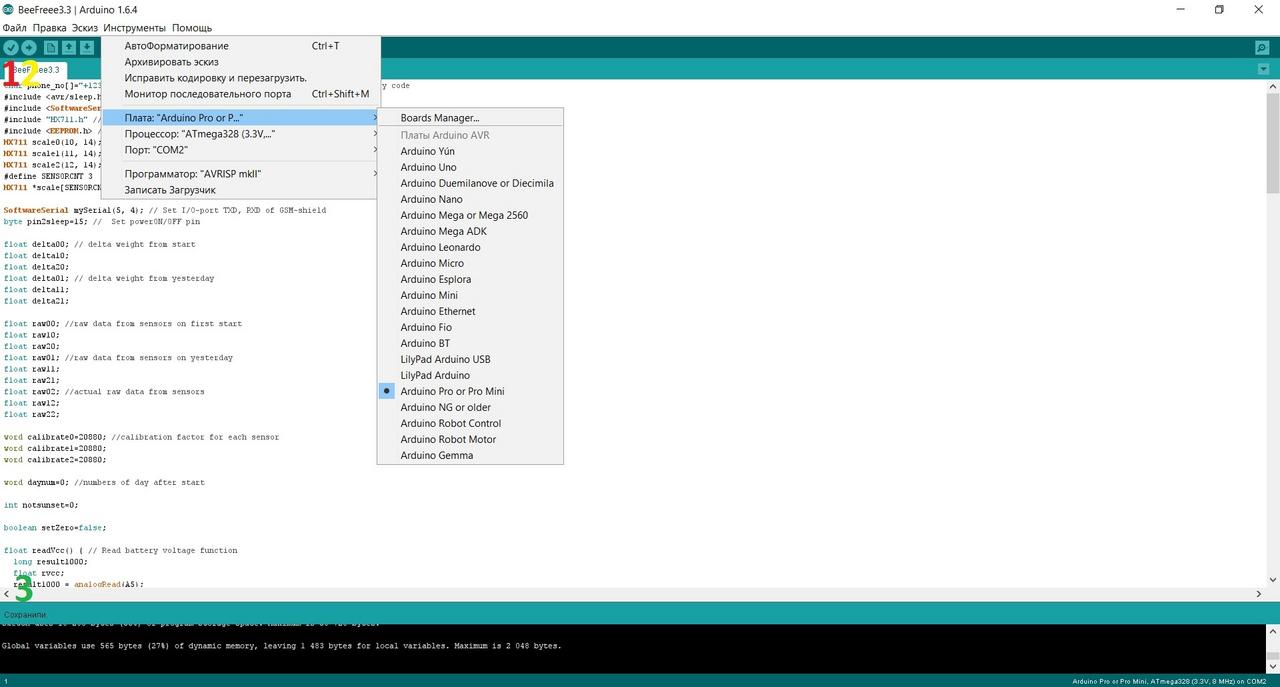
Go to "Tools" - select the "Arduino Pro or Pro Mini" board, Atmega 328 3.3V 8 MHz processor, port - number except the system COM1 (it appears after installing the CH340 driver with a USB-TTL adapter connected).
Ok, copy the following sketch (program), and paste it into the Arduino IDE window
char phone_no[]="+123456789012"; // Your phone number that receive SMS with counry code // NeverSleep #include <SoftwareSerial.h> // Sofrware serial library #include "HX711.h" // HX711 lib. https://github.com/bogde/HX711 #include <EEPROM.h> // EEPROM lib. HX711 scale0(10, 14); HX711 scale1(11, 14); HX711 scale2(12, 14); #define SENSORCNT 3 HX711 *scale[SENSORCNT]; SoftwareSerial mySerial(5, 4); // Set I/O-port TXD, RXD of GSM-shield float delta00; // delta weight from start float delta10; float delta20; float delta01; // delta weight from yesterday float delta11; float delta21; float raw00; //raw data from sensors on first start float raw10; float raw20; float raw01; //raw data from sensors on yesterday float raw11; float raw21; float raw02; //actual raw data from sensors float raw12; float raw22; word calibrate0=20880; //calibration factor for each sensor word calibrate1=20880; word calibrate2=20880; word daynum=0; //numbers of day after start int notsunset=0; boolean setZero=false; boolean forceSend=false; char ch = 0; char ch1 = 0; char ch2 = 0; char ch3 = 0; char ch4 = 0; void readVcc() // read battery capacity { ch = mySerial.read(); while (mySerial.available() > 0) { ch = mySerial.read(); } // empty input buffer from modem mySerial.println("AT+CBC?"); //ask gprs for battery status (for sim800 and neoway command must be "AT+CBC" ) delay(200); while (mySerial.available() > 0) { //read input string between coma and CR ch = mySerial.read(); if (ch ==','){ ch1 = mySerial.read(); ch2 = mySerial.read(); ch3 = mySerial.read(); ch4 = mySerial.read(); } } } // ********************************************************************** void SendStat() { detachInterrupt(digitalPinToInterrupt(0)); // turn off external interrupt digitalWrite(13, HIGH); if (!forceSend){ notsunset=0; for (int i=0; i <= 250; i++){ if ( !digitalRead(2) ){ notsunset++; } //is a really sunset now? you shure? delay(360); } } if ( notsunset==0 || forceSend ) { raw01=raw02; raw11=raw12; raw21=raw22; raw02=scale0.get_units(16); //read data from scales raw12=scale1.get_units(16); raw22=scale2.get_units(16); daynum++; delta00=(raw02-raw00)/calibrate0; // calculate weight changes delta01=(raw02-raw01)/calibrate0; delta10=(raw12-raw10)/calibrate1; delta11=(raw12-raw11)/calibrate1; delta20=(raw22-raw20)/calibrate2; delta21=(raw22-raw21)/calibrate2; readVcc(); delay(200); mySerial.println("AT+CMGF=1"); // Part of SMS sending delay(2000); mySerial.print("AT+CMGS=\""); mySerial.print(phone_no); mySerial.write(0x22); mySerial.write(0x0D); // hex equivalent of Carraige return mySerial.write(0x0A); // hex equivalent of newline delay(2000); mySerial.print("Turn "); mySerial.println(daynum); mySerial.print("Hive1 "); mySerial.print(delta01); mySerial.print(" "); mySerial.println(delta00); mySerial.print("Hive2 "); mySerial.print(delta11); mySerial.print(" "); mySerial.println(delta10); mySerial.print("Hive3 "); mySerial.print(delta21); mySerial.print(" "); mySerial.println(delta20); mySerial.print("Battery capacity is "); mySerial.print(ch1); mySerial.print(ch2); mySerial.print(ch3); mySerial.print(ch4); mySerial.println(" %"); if (forceSend) {mySerial.print("Forced SMS");} mySerial.println (char(26));//the ASCII code of the ctrl+z is 26 delay(3000); } forceSend=false; digitalWrite(13, LOW); attachInterrupt(0, SendStat , RISING); // Interrupt by HIGH level } // ************************************************************************************************* void switchto9600() { mySerial.begin(115200); // Open software serial port delay(16000); // wait for boot mySerial.println("AT"); delay(200); mySerial.println("AT"); delay(200); mySerial.println("AT+IPR=9600"); // Change Serial Speed delay(200); mySerial.begin(9600); mySerial.println("AT&W0"); delay(200); mySerial.println("AT&W"); } void setup() { // Setup part run once, at start pinMode(13, OUTPUT); // Led pin init pinMode(2, INPUT_PULLUP); // Set pullup voltage Serial.begin(9600); // ------------------------------------------------------------------------------- switchto9600(); // switch module port speed // ------------------------------------------------------------------------------- mySerial.begin(9600); delay(200); scale[0] = &scale0; //init scale scale[1] = &scale1; scale[2] = &scale2; scale0.set_scale(); scale1.set_scale(); scale2.set_scale(); delay(200); setZero=digitalRead(2); //if (EEPROM.read(500)==EEPROM.read(501) || setZero) // first boot/reset with hiding photoresistor if (setZero) { raw00=scale0.get_units(16); //read data from scales raw10=scale1.get_units(16); raw20=scale2.get_units(16); EEPROM.put(500, raw00); //write data to eeprom EEPROM.put(504, raw10); EEPROM.put(508, raw20); for (int i = 0; i <= 24; i++) { //blinking LED13 on reset/first boot digitalWrite(13, HIGH); delay(500); digitalWrite(13, LOW); delay(500); } } else { EEPROM.get(500, raw00); // read data from eeprom after battery change EEPROM.get(504, raw10); EEPROM.get(508, raw20); digitalWrite(13, HIGH); // turn on LED 13 on 12sec. delay(12000); digitalWrite(13, LOW); } delay(200); // Test SMS at initial boot readVcc(); delay(200); mySerial.println("AT+CMGF=1"); delay(2000); mySerial.print("AT+CMGS=\""); mySerial.print(phone_no); mySerial.write(0x22); mySerial.write(0x0D); // hex equivalent of Carraige return mySerial.write(0x0A); // hex equivalent of newline delay(2000); mySerial.println("INITIAL BOOT OK"); mySerial.print("Battery capacity is "); mySerial.print(ch1); mySerial.print(ch2); mySerial.print(ch3); mySerial.print(ch4); mySerial.println(" %"); mySerial.println (char(26));//the ASCII code of the ctrl+z is 26 delay(3000); raw02=raw00; raw12=raw10; raw22=raw20; attachInterrupt(0, SendStat , RISING); // Interrupt by HIGH level } void loop() { digitalWrite(13, LOW); ch=mySerial.read(); if ( ch=='R' ) { //wait first lerrer from "RING" string forceSend=true; mySerial.println("ATH"); SendStat(); ch=' '; } } In the first line, in quotes char phone_no [] = "+ 123456789012"; - instead of 123456789012 we put our phone number with the country code, which will receive SMS.
We press the check button (above the number one in the screenshot above) - if below (under the triple on the screen) "Compilation is complete" - then we can flash the microcontroller.
So, USB-TTL is connected to ARDUINO and the computer (as in the photo above), we put the charged battery in the holder (usually the LED on the new arduinka blinks once a second).
Now the firmware - we are training to press the red (silver) button of the microcontroller - this will need to be done strictly at a certain moment !!!
There is? We press the button "Load" (above the two in the screenshot), and carefully look at the line at the bottom of the interface (under the triple screen).
As soon as the inscription "compilation" is replaced by "loading" - press the red button (reset) - if everything is ok - the lights on the USB-TTL adapter blink, and at the bottom of the interface the inscription "Loaded"
While we are waiting for the arrival of the test SMS on the phone, I will tell you how the program works:
The first time the system is turned on, the system checks the bytes number 500 and 501 of the EEPROM; if they are equal, then the calibration data is not recorded, and the algorithm goes to the settings section.
The same happens if the photoresistor is shaded when turned on (cap from the pen) - the reset mode is activated.
Strain gauges should already be installed under the hives, since we simply fix the initial level of zero and then measure the change in weight (now just zero will come, since we haven’t connected anything yet).
At Arduino, the built-in LED of pin 13 will start blinking.
If the reset does not occur, the LED lights up for 12 seconds.
After that, a test SMS is sent with the message "INITIAL BOOT OK" and the percentage of battery charge.
Further, we have an interruption on the photosensor on the second pin (the pullup plus feature is enabled by the pullup function).
At the same time, after triggering another 3 minutes, the state of the photoresistor is checked - to avoid repeated / false positives.
In order for the system not to reset every time it is turned on, at least the first HX711 module must be connected (pins DT-D10, SCK-A0)
Then the load cell readings are taken, the weight change from the previous response (the first number in the row after Hive) and from the first start is calculated, the battery voltage is checked and this information is sent as SMS:

By the way, received SMS? Congratulations! We are in the middle of the road! The battery can be removed from the holder, the computer will not be needed further.
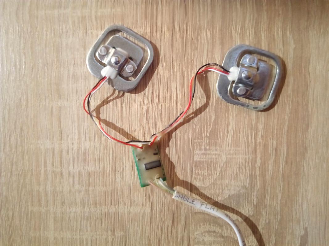
Proceed to the manufacture of sensors, for the beginning let's touch the layout of the sensors:
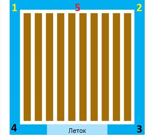
This is a hive plan - a top view.
Classically, 4 sensors are installed in the corners (1,2,3,4)
We will measure differently. Or rather, even in the third. Because the guys from BroodMinder do it differently:
In this design, the sensors are installed at positions 1 and 2, points 3.4 rely on the beam.
Then the sensors account for only half the weight.
Yes, this method has less accuracy, but still it is difficult to imagine that the bees build up all the frames with "tongues" from the cells along one wall of the hive.
So, I propose to reduce the sensors to point 5 in general - then there is no need for shielding the system, and when using light hives, you can do just one sensor.
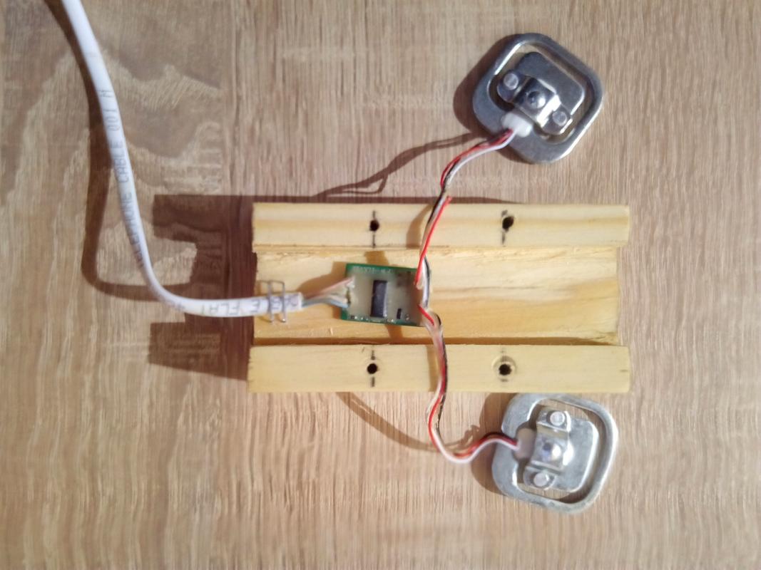
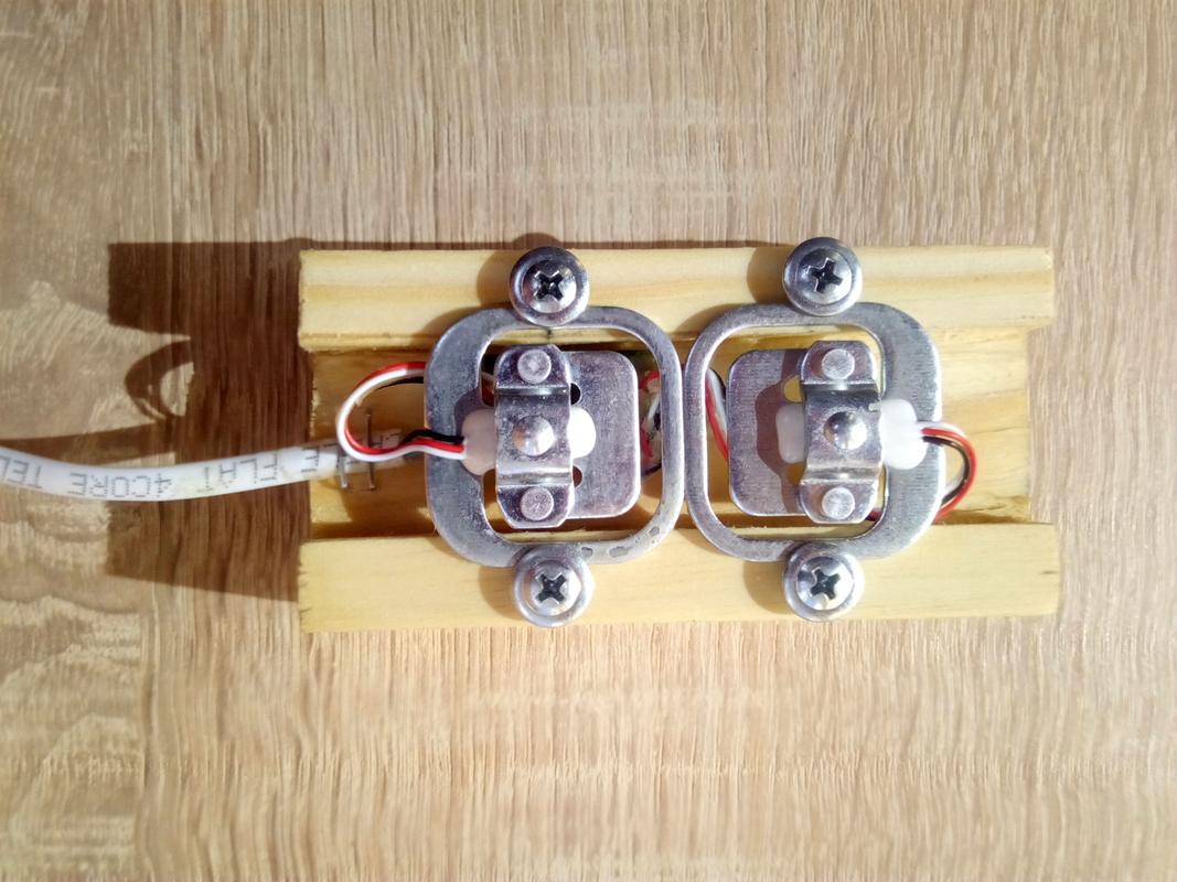
So, for one hive, we will have two strain gauges and one HX711 module, the decoupling scheme is as follows:
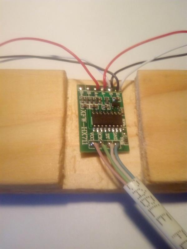
From the ADC board to the Arduino, there is 5 meters of a 4-wire telephone cable (in the case of modules of weight 2 and 3), the first sensor is connected with a 10 cm tail, but more on that later.
In general, we leave “tails” of 8 cm on the sensors, we clean the twisted pair and we solder everything as in the photo above.
Before starting the carpentry part, put the wax / paraffin in a suitable container to melt in a water bath.
Now we take our timber and divide by three pieces of 100mm
Next we mark the longitudinal groove 25 mm wide, 7-8 mm deep, with the help of a hacksaw and chisel we remove the excess - a U-shaped profile should come out.
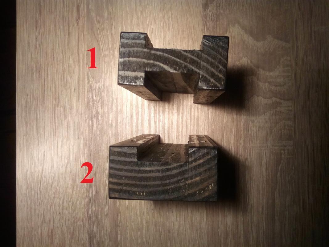
In fact, we need one N-shaped part 1 and two - P-shki, all 10 cm long.
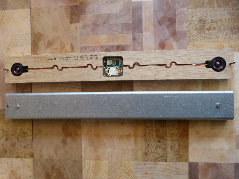
Why N-ka - do not believe it, we hide Arduino:
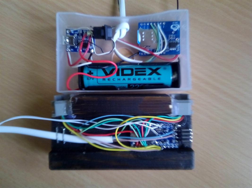
In addition, the 6P6C sockets for connecting sensors 2 and 3 are also attached here.
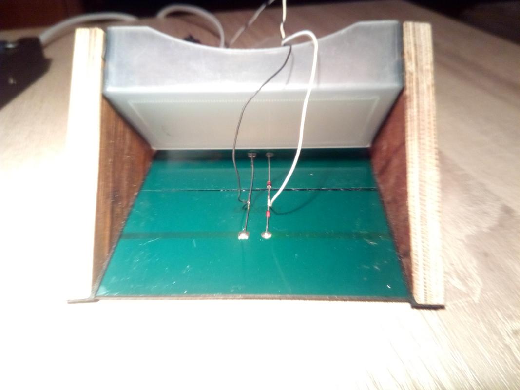
Is the wax warming up? - we dip our ADC boards there - this will protect them from moisture / fog:
We place it all on a wooden base (must be treated with antiseptic from rotting):
And finally, fix the sensors with self-tapping screws:
Next, we solder all the remaining components according to the scheme in the header and common sense.
In terms of the location of the components, it is desirable to show imagination, you should consider one thing - the distance between the microcontroller and the GSM-module must be at least one meter!
I have the same design:
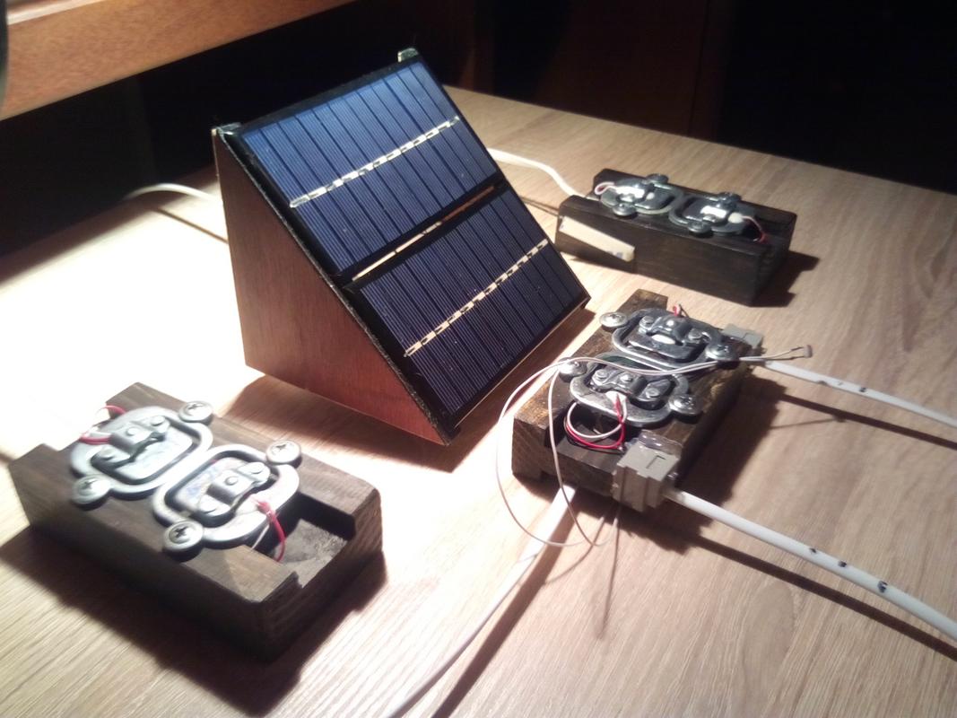
Yes, the installation angle of the panels, I took 45 degrees - because of the simplicity of manufacture, but it is close to the forty degrees that are optimal for summer at the latitude of Kiev.
Everything, now for the final check, we put the sensors on sectors of the circle, on top - a piece of plywood, reset the controller (turn on the system with the pen cap on the photodiode).
At the same time, the LED on arduinka should blink and test SMS should arrive.
Then we remove the cap from the photocell, and go to collect water in a 6 - liter plastic bottle.
We put the bottle on plywood and if several minutes have already passed from switching on, put the cap back on the photoresistor (imitating the sunset).
At the same time, the Arduino LED will light up, and you should receive an SMS with weight values of about 4 kg in all positions.
Congratulations! system successfully assembled!
If we now make the system work again, then in the first column of weight we get zeros.
Yes, in real conditions the photoresistor is desirable to be oriented vertically upwards.
Now I will give a brief manual for use:
- Install strain gauges under the rear walls of the hives (substitute a bar / board ~ 30mm thick under the front)
- Install a communication module with solar panels on an elevation, with a distance of several meters from the hives.
The orientation of the solar panels - to the south - can be on a compass (we will not catch the true one). - Shade the photoresistor and put the battery - the LED should blink and test SMS with the text "INITIAL BOOT OK" should come
Every evening, after sunset, SMS will arrive with a change in weight per day and from the moment of launch.
When you call the SIM-card number of the GSM module, the controller hangs up (we hear "The subscriber cannot receive the call") and an SMS arrives with extraordinary measurements.
In such a message will be an additional line - "Forced SMS";
Very little is left to the complete beauty of the system:
- Add a hardware autoreset system on the photosensor.
- Check other types of communication modules.
- Do everything under the ESP-8266 - firstly, it supports updating the firmware "over the air" - it is convenient the same.
Secondly - it can give statistics in the form of simple web pages.
And finally, if you have Wi-Fi, you can refuse GSM at all.
Oh yeah, I’m tired of messing with wires, and I promised a system with "absolute" energy saving.
In short, I decided to "fool around" a bit and do it all.
As far as possible - read the publication in a month!
See you on the pages of Habr,
The Electric Beekeeper Andrei
')
Source: https://habr.com/ru/post/448274/
All Articles