Visual logic editor for Unity3d. Part 1
Introduction
Hello dear readers, in today's article I would like to dwell on this phenomenon in the development of applications on Unity3d , such as visual development or, more precisely, development using visual presentation of code and logic. And, before continuing, I want to clarify right away that we are not talking about visual programming, from the word “absolutely”, no Blueprint variations in the Unity world and no generations of C # code. So what is meant by the visual editor of logic? If you are interested in the answer to this question, welcome under cat.
What is a visual logic editor?
Very often, and some say that during development, programmers write a lot of different code that does a lot of different things, from system tools to game mechanics. This code, if the programmer is “real,” is usually made unified and isolated so that it can be reused (within Unity, this code is the components, they are also MonoBehior’s heirs). It is not difficult to imagine that there can be a lot of such code, especially if this is not the first project. And now let's imagine that we are starting a new project and we need to make a lot of fast and different prototypes, and the team of programmers is limited, and the whole is busy with the main project or projects. Game designers are indignant, they need to test, check, producers run around managers trying to get a programmer for themselves, money is limited, time is running, etc., etc.
The other side of the coin, we (the programmers) wrote a lot of code in the form of components, they hang a large list on different objects of the scene. And here we are expanding the team, hired a new programmer, he opens the stage to figure out and is drowning in the mess of questions: who causes whom, in what order, what component is connected with which and how, etc. You reasonably say: - “And Documentation? ”Documentation is (although not at all a fact), but here it is a question of the lowest possible entry of new people into the team, and the time for this process is as short as possible.
How to solve the above situation? The answer in the title of the article is the Visual Logic Editor. What is it? This is an environment that allows you to visually operate with various components of logic and adjust their interrelations (in the “soft” version), as well as indirectly from the scene to operate with objects of the scene. If we describe it in a fabulously simple way, then it’s like in childhood to assemble different constructions from cubes (only in our case, the cubes are not rigidly interconnected, removing the lower one, our construction will not fall).
')
So, we have dealt with the definition, but what does this give us in the end?
- You can collect universal designs that can be reused in projects, which reduces the subsequent routine. Imagine some kind of pure field, which is our project, we just take the assembled structure from another game, put it on the field and that's it.
- It is possible to create a base of isolated “cubes” (mechanic, logician, functional) from which people who are not programmers could assemble the structures themselves.
- It is possible to replace constructions with others on the fly, thereby changing the behavior of logic.
- You can use constructions in deferred mode, for example, if the NPC is not present in the world now, then no logic associated with it will exist on our “field”.
- Since our cubes are not connected by rigid connections between each other, we can turn them off and turn on as we please and implement arbitrarily complex conditional and unconditional branching.
Well, that sounds pretty good? And what about the reality? If you open the Asset Store and see the Visual Scripting section, you can see, in principle, a large number of different plugins. Most of them are variations on the Blueprint theme from the Unreal Engine, i.e. essentially code generation. There are practically no systems that fit the concept of a visual editor of logic. The closest ones are:
- Playmaker . Yes, this is the FSM plugin, but nevertheless, it allows you to write your Actions. It is not so convenient from the point of view of the interface, but for certain things it is very good. Blizzard knowingly used it in Hearthstone.
- Behavior Designer / MoonBehavior , etc. state tree plugins. Already closer to what was described above, but a lot of limitations, after all, the state tree is not full-fledged logic on the components.
- Icode . This is an analogue of playmaker, that is, in fact, also a state machine.
Is there a way out, you ask, dear readers? I found only one to write my system, which I did, but the path to it was rather long and thorny.
Way
The idea to develop a visual logic plugin for Unity3D has arisen for a long time. At first it was just the thought that if it were like this, it would be cool. These thoughts appeared in the process of working on a project in which there were a lot of similar games, more than 20 pieces that had to be done very, very quickly. The first implementation was terrible in terms of the interface, although, of course, it allowed us to successfully develop the entire set of games at a given speed.
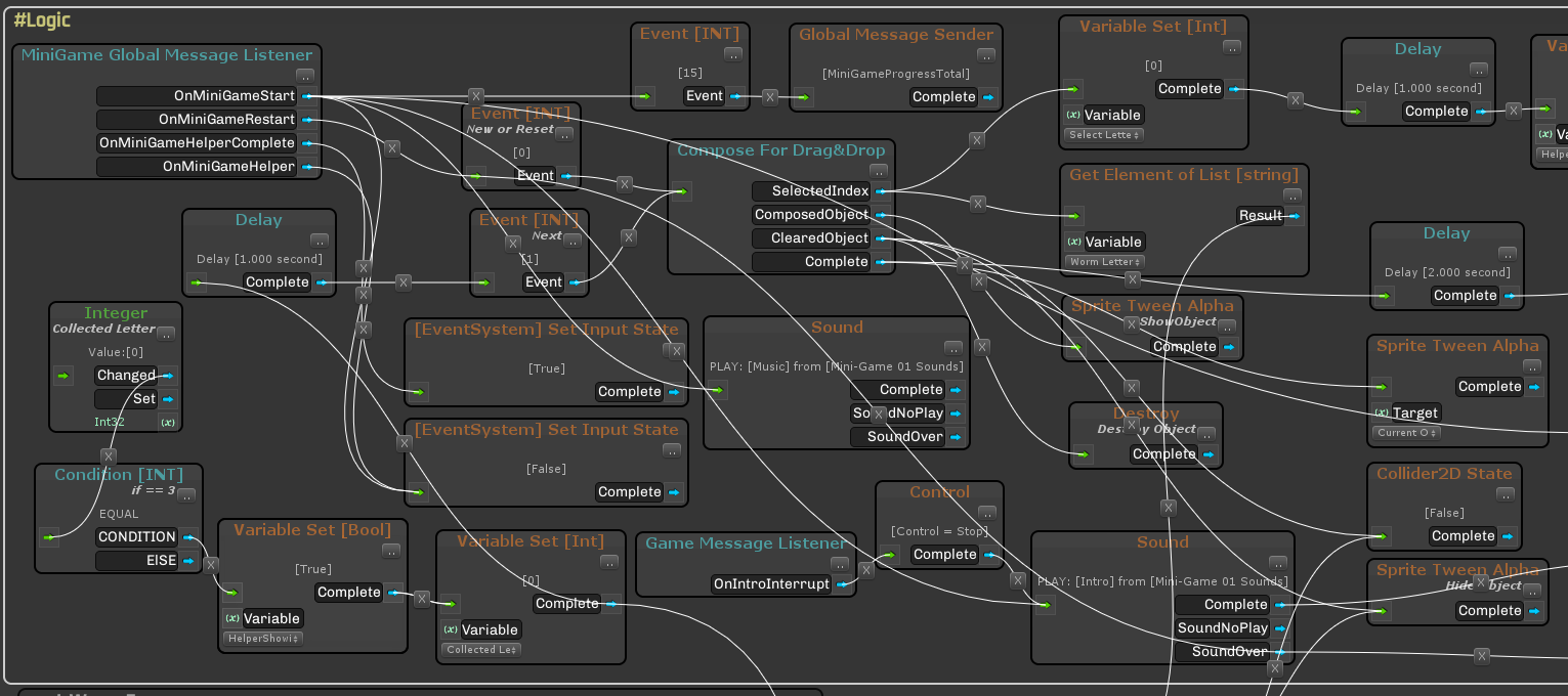
For the next project, it was decided to do a full-fledged visual editor, but in the end, because of the small experience, the implementation was not successful, everything was wildly slowed down, the number of links, etc. things went off scale so that it was impossible to figure out where (see screenshot and do not be scared).
After that, for some time the idea was postponed. I have already done the following projects on clean code, but the idea was still in my head. Gradually, taking into account past mistakes, the final (as it seemed to me) vision and list of requirements was formed. And in 2017, after the completion of the next freelancing project, I decided that I can afford to spend 6-7 months to work on this plugin and try to put it in the Asset Store (it still lies and is called Panthea VS ). From the point of view of work experience on such a complex project, everything was very cool, alas, the financial side is sad, after all being able to program and be able to sell, these are different things. It was November 2017, after which I slightly lost my motivation, divorced, changed the city, completely changed my life, and in order not to fall into samoedstvo I decided to look from a different angle on the theme of the visual editor of logic. The result was uViLEd , which I decided to post for free. Since I signed a full-time contract, I had to work on it on weekends and holidays, and it took all of 2018 and the beginning of 2019. uViLEd is a great rethinking of Panthea VS , full refactoring of the code under the Roslyn compiler (C # 7+), so everything works only starting from version 2018.3 of Unity3d.
Note : Several projects came out on Panthea VS (Android and iOS, in particular Lev's Truck and Typewriters), in principle, the experience is good, but the moment came that it’s one thing to write an editor, another thing is to learn how to use it correctly (no matter how strange it sounds ).
uViLEd and how to use it
Introduction
So, what I got in the end, first we look at the picture, and then we continue (there will be more pictures later).

What is basically a visual editor of logic.
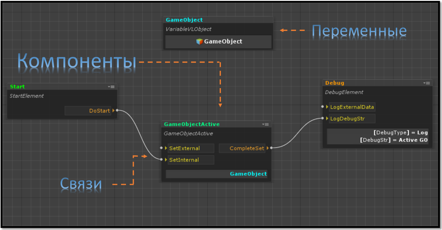
Here:
- Components are our code that implements this or that functionality, in fact, an analogue of MonoBehaviour , only in our case all components are inherited from the LogicComponent class, which in turn is ScriptableObject .
- Variables are such special ScriptableObjects that are allowed to store data (any, including custom structures and classes, links to scene objects, prefabs and assets). Variables are needed if it is necessary to make the data shared between components, that is, each component can refer to a variable of the desired type, and it will be one.
- Relationships are descriptions in visual form of which components, how and in what order the methods of each other are called. The relationships between components are defined using two specialized fields of the types INPUT_POINT and OUTPUT_POINT . A link is always formed as the output point of a component at the input point of another component. These links are not rigid, that is, they are not visible to the programmer and are not in the code either. They are present, only in the editor, and then when the scene is started, the logic controller itself understands the code. How this happens we will talk in a separate article.
Everything in a compartment — components, variables, and connections — form the logic . In general, nothing supercomplex, the programmer writes the code of components and variables, and the game designer or another (and maybe the same) programmer / script creates the logic by placing these components in the editor and setting up links and parameters.
Key features uViLEd
- Running logic (a set of components, variables and connections) in deferred mode, including starting from an external source (hard disk or server)
- Configure connections between components (call order, activation and deactivation)
- Easy integration of components and any other code, including MonoBehavior heirs
- Redefining the appearance of components in the editor (analogue to CustomPropertyDrawer)
- Setup of parameters of components through the inspector Unity3d
- Simple addition of components to the logic via the Drag & Drop script file or through the directory
- Component Grouping in Logic Editor
- Setting the display of components in the editor (inversion, minimization, activation and deactivation)
- Opening the component code editor directly from the logic editor
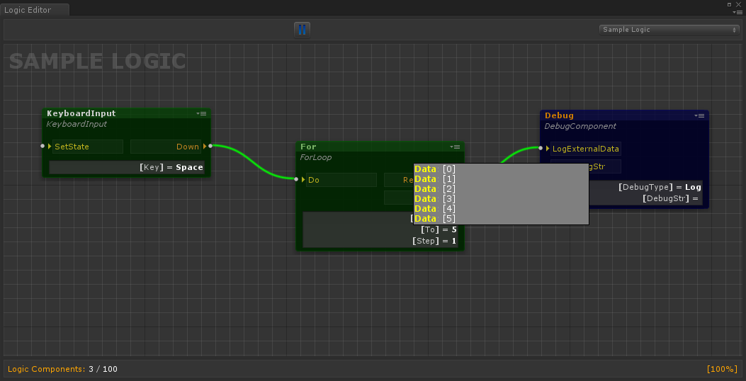
- Displaying debug data directly in the logic editor during startup in the editor
- Scaling visual logic editor
- If suddenly there are a large number of components in logic, then there is a possibility of searching them with focus when selecting (this also applies to variables)
- Step-by-step debugging in scene launch mode in the Unity3d editor with tracking of all transmitted data between components and variable values
- Supports MonoBehaviour methods and setting the order in which they are called. Note : here it is meant that by default there are no methods of type Start, Update, etc. in SO. therefore, their support has been added to the components themselves. In this case, using the ExecuteOrder attribute, you can customize the order in which the Start, Update, etc. methods are called.
- Support for Coroutine, async / await and all Unity3d attributes for the inspector, as well as support for CustomPropertyDrawer
Work with the editor
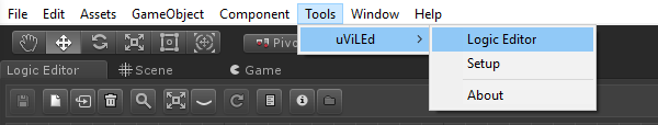
To start working with the editor, you need to open the scene and then start the editor itself.
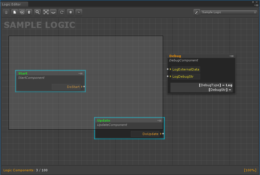
After launching the editor, we initialize the scene (the refresh button in the editor), after which it will be possible to create or add existing logic to the scene.
After creating the logic (the file that will describe the components, their parameters, relationships between components, variables and their values), you can fill it with meaning. To add a component or variable, simply drag the corresponding script into the area of the logic editor. An alternative option is to use a directory that is generated automatically using the ComponentDefinition attribute.

After we have added several components to the logic, they can be moved, including groups or combined into a visual group.
Let us consider in more detail what we are representing the component itself in the visual editor.
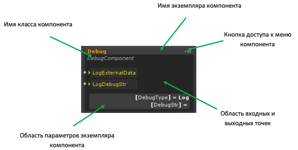
Here:
- The component's menu button opens a drop-down menu with which you can:
- Activate or deactivate the component
- Minimize the component (you can also do this by double clicking on the title)
- Invert component (swap input and output points)
- Hide or show component parameter area
- Open the component code editor.
- The component parameter area is the place where the values of the key component parameters are displayed, the composition of which depends on the programmer.
To configure the parameters (public fields or fields with the SerializeField attribute), you need to select the component in the logic editor and open the Unity3d inspector.
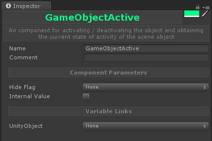
Here:
- In the upper right corner there is a button that allows you to change the color of the header, which is displayed in the logic editor.
- Name - field to set the name of the component instance
- Comment - the field for setting a comment to the component instance, is displayed in the logic editor when you hover the mouse cursor over the component
- Component Parameters - the area where the component parameters are displayed (public fields and fields marked with SerializeField)
- Variable Links - an area for setting references to variables (for more details, see the section on working with variables).
In order to visually group objects you need to select them, and then press the right button and select the corresponding item in the menu. Groups can be renamed, as well as change their colors.
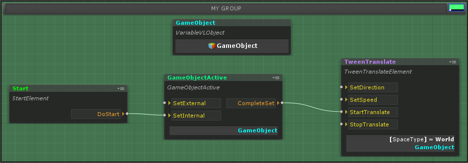
To scale the visual representation of the components, use the mouse wheel, everything is quite simple.
And the last thing I want to draw attention to is working with links between components.
To establish a connection, it is necessary to connect the output point of one component to the input point of another.
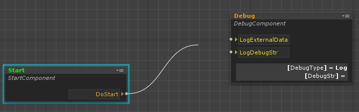
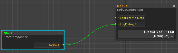
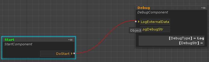
Links are established based on the type matching rule that the point transmits and receives. An exception is made for an input point that does not accept data; any output point can be connected to it. When a connection is established, the system automatically checks the type match and shows whether it is possible to establish this connection. Input and output points are specified in the component code using the following classes:
INPUT_POINT OUTPUT_POINT INPUT_POINT<T> OUTPUT_POINT<T> The first two classes are used for the input and output points that do not accept parameters, the second, respectively, vice versa. T can be any type.
public INPUT_POINT <float> InputFloatValue = new INPUT_POINT<float>(); public OUTPUT_POINT <float> OutputFloatValue = new OUTPUT_POINT<float>(); In order to call a chain of links, you must use the function Execute.
OutputFloatValue.Execute(5f); In order to handle such a call, in the component code you need to install a handler for the input point (about exactly where we will talk later).
InputFloatValue.Handler = value => Debug.Log(value); And in conclusion, I want to mention an important point about connections. If there are several connections from one point, then the editor has the ability to customize the order of their call.
Work with variables
As mentioned earlier, variables are special objects that allow data to be shared between components through references to them. Variables, like components, are created by programmers.
[ComponentDefinition(Name = "Float", Path = "uViLEd Components/Base/Variable/Base", Tooltip = "Variable for a floating-point number", Color = VLEColor.Cyan)] public class VariableFloat : Variable<float> { } As you can see, the base class for variables is the generic class Variable, where T is the data type that is enclosed in a variable, T can be any type that can be serialized.
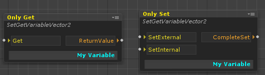
In the editor, variables are displayed as follows:
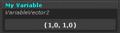
To change the display of the values of a variable, simply override the ToString method in the T type.
public struct CustomData { public readonly int Value01; public readonly int Value02; public CustomData (int value01, int value02) { Value01= value01; Value02= value02; } public override string ToString() { var stringBuilder = new StringBuilder(); stringBuilder.AppendLine("Value01 = {0}".Fmt(Value01)); stringBuilder.Append("Value02 = {0}".Fmt(Value02)); return stringBuilder.ToString(); } } Thus, a variable of this type will look like:
public class VariableCustomData : Variable<CustomData> { } In order to add a reference to a variable in a component, you must use a special class.
public VARIABLE_LINK<CustomData> CustomVariableLink = new VARIABLE_LINK<CustomData>(); After that, the link can be set in the inspector, while in the drop-down menu, I will show only CustomData variables, which greatly simplifies working with them.
For the convenience of working with variables, there are special methods that allow you to determine when a variable has changed its value or when any data has been set to it.
CustomVariableLink.AddSetEventHandler(CustomDataSet); CustomVariableLink.AddChangedEventHandler(CustomDataChanged); It is worth considering here that Changed works on the Equals condition, therefore, if structures and classes are used, this method must be redefined to ensure correct operation.
Work with Unity Objects
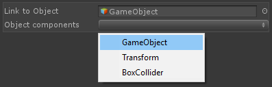
Due to the peculiarities of the uViLEd system, direct links to Unity objects cannot be used in it, since they cannot be restored when loading logic. To solve this problem, a specialized VLObject shell was created that allows you to create such links, as well as save and load them. Among other things, this shell has a special property editor that allows you to get components from any scene object (see the figure below) if you want to access them. With VLObject, you can store links not only to scene objects and their components, but also to prefabs and resource files, such as textures, sounds, etc.
Note : if existing logic is used in another scene, the object references will be lost, including prefab references, because the scene acts as their repository. This also needs to be taken into account if you plan to use logic as a template, in this case the best option would be to transfer the necessary references to it from the outside (for example, from logic tied to the scene).
It is also possible to restrict the type of Unity object that will be set to VLObject . This only affects the Unity inspector and is used for convenience.
[SerializeField] [TypeConstraint(typeof(Button))] private VLObject _button; Creating a logic component
In order to create a logic component, it is enough for a programmer to add a simple C # script file to a project (you can also create a component or variable right through the special menu in the Project tab) and change the code in it to the following:
[ComponentDefinition(Name = "MyComponent", Path = "MyFolder/MySubfolder", Tooltip = "this my logic component", Color = VSEColor.Green)] public class MyLogicComponent : LogicComponent { } As mentioned earlier, ComponentDefinition is an attribute that allows you to automatically generate a catalog of components, here it should be noted that Color (header color) is set in a string in the form of a HEX format.
LogicComponent is the base class of all components, which in turn is a successor of ScripatableObject .
Below is a simple example of a component that makes a branch on an incoming value of type bool:
public class IfBool : LogicComponent { public INPUT_POINT<bool> ValueToBeChecked = new INPUT_POINT<bool>(); public OUTPUT_POINT True = new OUTPUT_POINT(); public OUTPUT_POINT False = new OUTPUT_POINT(); public override void Constructor() { ValueToBeChecked.Handler = ValueToBeCheckedHandler; } private void ValueToBeCheckedHandler(bool value) { if(value) { True.Execute(); }else { False.Execute(); } } } So, as can be seen from the code, we created an input point for the component, which takes a value of type bool and two output points that are called depending on what value we received.
Perhaps you now have a question, what kind of Constructor is this? I explain. By default, ScriptableObject does not support Start , Update , etc. methods, but it supports the Awake , OnEnable , OnDisable, and OnDestroy methods. So, Awake (as well as OnEnable ), in case ScriptableObject is created via the CreateInstance method, is always called, and this is actually the problem. Due to the fact that an object is created in memory for serialization in the editor mode, it was necessary to exclude the work of the component code at that moment, therefore the Awake analogue was added in the form of the Constructor method, the same applies to the OnDisable and OnDestroy methods when deleting an object in the editor. If you need to correctly handle the removal of a component (when unloading a scene, for example), you must use the IDisposable interface.
In general, as you can see, there is nothing difficult in creating components. This is a normal class, which can be any code you want. In the particular case of the components in general may not contain input and output points, and communicate using global messages. By the way, for this there is a GlobalEvent class in uViLEd - this is a message system based on data types (you can read more about it in my article).
The last thing I would like to mention is the ability to configure the input and output points of the component, depending on the parameters of the component.
To do this in the component code, it is enough to implement one or both of the IInputPointParse and IOutputPointParse interfaces . Below is a sample code of an abstract generic class for Switch branching components, output points are automatically created here, depending on the SwitchValues parameter.
SwitchAbstract class code
public abstract class SwitchAbstract<T> : LogicComponent, IOutputPointParse { [Tooltip("input point for transmitting value, which should be checked")] public INPUT_POINT<T> ValueToBeChecked = new INPUT_POINT<T>(); [Tooltip("set of values for branching")] public List<T> SwitchValues = new List<T>(); protected Dictionary<string, object> outputPoints = new Dictionary<string, object>(); public override void Constructor() { ValueToBeChecked.Handler = ValueToBeCheckedHandler; } protected virtual bool CompareEqual(T first, T second) { return first.Equals(second); } protected virtual string GetValueString(T value) { var outputPontName = value.ToString(); #if UNITY_EDITOR if (!UnityEditor.EditorApplication.isPlaying) { if (outputPoints.ContainsKey(outputPontName)) { outputPontName += " ({0})".Fmt(outputPoints.Count); } } #endif return outputPontName; } private void ValueToBeCheckedHandler(T checkedValue) { foreach (var value in SwitchValues) { if (CompareEqual(checkedValue, value)) { ((OUTPUT_POINT)outputPoints[GetValueString(value)]).Execute(); return; } } } public IDictionary<string, object> GetOutputPoints() { #if UNITY_EDITOR if (!UnityEditor.EditorApplication.isPlayingOrWillChangePlaymode) { outputPoints.Clear(); } #endif if (outputPoints.Count == 0) { foreach (var value in SwitchValues) { outputPoints.Add(GetValueString(value), new OUTPUT_POINT()); } } return outputPoints; } } Debugging logic
To debug logic, uViLEd provides several mechanisms:
- Ability to display internal variables and their values in the logic editor in the scene run mode. To do this, use the ViewInDebugMode attribute .
- Ability to view the values of logic variables in the scene run mode
- Possibility of step-by-step debugging of the call of links between components and viewing of the data that is transferred between them
For the last item in uViLEd, a special mode is provided, which is turned on when the scene starts.
This mode, unfortunately, has certain limitations associated with the transition between scenes. In this case, the debug data from the previous scene and the logic will be lost, and in the new one they will be displayed only from the moment when the logic is activated in the editor.
Conclusion
In this article I have tried to briefly introduce you to the development approach that I use in my current projects. Despite the initial skepticism (and mine as well), practice shows much the convenience of its use, especially when prototyping. Among other things, the work of game designers has been greatly simplified, they do not climb into the scene, do not poke objects to customize the gameplay, they create a separate logic with a set of variables and components in which they can easily tune everything. Also of great advantage is the fact that in my projects, often the content is loaded from the outside. Using the visual logic editor, I can update the balance of the gameplay without updating the main application, in some cases, the logic itself can be changed.
For myself, I decided that a similar approach to development is quite possible to be, of course it does not apply to large projects, but it can be used there for some gameplay scripts to revitalize the world, in level design, etc. In my current projects (children's segment), he, so far, perfectly manifests itself.
What next?
This was the first part of a series of articles about the visual editor of the logic uViLEd, then there will be parts about:
- The core of the system : how the logic is loaded, why the ScriptableObject is selected, how the API is organized, what it allows to do, etc., what difficulties have arisen and how everything has been solved.
- Editor : how it was developed, how it works, what problems and what solutions, etc. things that would be redone now.
Write in the comments if you have specific questions that you want me to consecrate in subsequent articles.
PS : I tried to tell about the key points of uViLEd , if you have a desire you can read it by downloading the plugin from the Asset Store, there is complete documentation (though in English): user manual, guide for programmers and API.
Visual Logic Editor uViLEd
Global Messaging Article
Source: https://habr.com/ru/post/448190/
All Articles