Test drive nanoCAD SPDS Metal structures 1.2. Part 1
Test Drive
nanoCAD SPDS Metalware 1.2

Dear habrovtsy interested in CAD,
For several months of blogging at Habré, we received many questions about the basic tools of the SPDS Metalware and SPDS programs Building site. Therefore, we decided to create and publish test drive materials on these solutions on the nanoCAD platform. The materials will be published in parts and will help everyone who prefers to master the software on their own, get acquainted with the interfaces of the programs and go through the main design steps in them.
')
We start with nanoCAD SPDS Metal structures . In this publication, you will learn how to create a new project, a new assembly, an array of axes, learn how to create columns and beams and place them on the plan.
The program nanoCAD SPDS Metal 1.2 is designed to automate the development of design documentation brands KM.
The graphic core of nanoCAD SPDS Metal structures is the Russian graphic platform nanoCAD Plus 10.0, and the entire embedded functionality of nanoCAD SPDS 9.0 is used as the design tools for GOST.
Metallic structures are implemented in the form of parametric objects, which allows you to automatically generate statements of elements and specifications of metal.
This technical demonstration is intended to familiarize the end user with the basic features of the program nanoCAD DPS Metal Structures 1.2. The demonstration is based on the implementation of a specific example (building the skeleton of an industrial building), in which a number of operations are necessary to optimally understand the basic functionality of the program. To familiarize yourself with all the features of the program, use Help , which can be called up from the program by pressing the F1 key.
Chapter 1. Creating a New Project
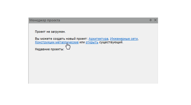
1.1. When you first start the program nanoCAD SPDS Metal structures in the window of the project manager, you need to select one of the options to start working on the project. You can load a previously completed project or create a new one. Let's create a new project by selecting the Metal Construction option.
Chapter 2. Creating a new assembly.
2.1. Create an assembly. Select the Assembly command from the drop-down list and click on it with the mouse cursor.
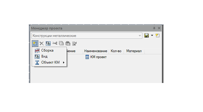
2.2. By default, the assembly was created, now this assembly must be renamed.

2.3. In the designation we indicate the code of the project, and in the name we write the name of the project.

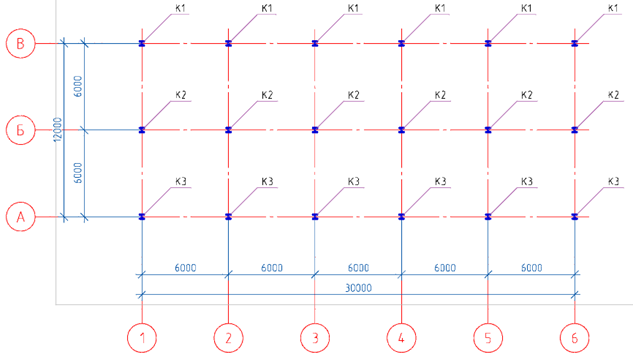
Chapter 3. Creating an array of axes.
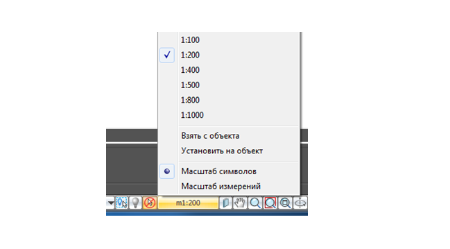
3.1. Before creating an array of axes, set the drawing scale to 1: 200 .
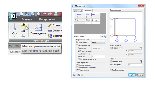
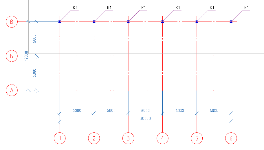
3.2. On the toolbar SPDS call the command Array of orthogonal axes . In the dialog box, set the number of steps along the letter axes - 2, the number of steps along the digital axes - 5. Let’s leave the step of the letter and number axes to 6000mm by default. Click OK and place the array of axes in the drawing model.

Chapter 4. Creating columns and placing them on the plan.
4.1. The main controls are the toolbar, the properties window, the context menu, and the command line .
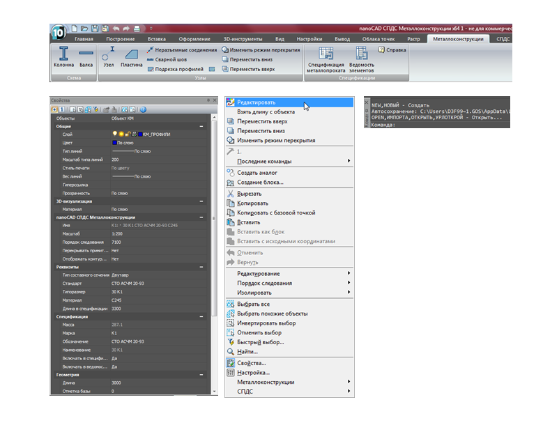
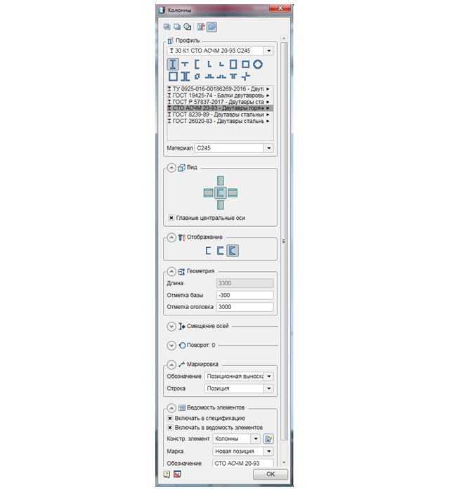
4.2. On the Metal Toolbar, we call the Column command, then in the dialog window that appears, set the necessary parameters.

4.3. To begin with, in the upper part of the dialog, you need to click on the Insert several icon, so that with several successive inserts into the drawing of this column, its mark does not automatically change (the column will be inserted with one mark).

4.4. In the dialog, set the necessary parameters for the column:
- We select the profile of the I-beam, column type according to the standard STO ASCM 20-93 and frame size 30K1. C245 steel material .
- View - "section".
- The display is “full”.
- In the Geometry tab, set the base level to -300, and leave the ogolovka mark to 3000 by default (we will correct the ogolovka mark when building the section).
- The Offset Axis tab is left unchanged (the center of the section).
- The Rotate tab is left unchanged (“0” rotation).
- The marking tab is left unchanged (positional callout, position).
- In the Sheet Items tab, we tick Include in specification and Include in item list . The type of the structural element is left by default (columns).
4.5. Having set all the parameters, click OK and place the columns along the "B" axis.
4.6. Having placed the columns, we finish the command by pressing the Esc key .
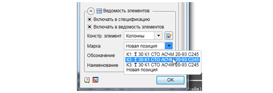
Attention! If for any reason you interrupted the layout command for the structural elements in the drawing and again want to continue placing the elements with the same brand and parameters, then you need to call the Beam / Column command and then select the required Element Mark in the Sheet of Elements tab.
4.7. Next, we need to place the columns along the axis "B" and "A". To do this, we call the Column command again, in the dialog window that appears, the program has already saved the previously entered parameters, click OK and place the columns along the axis “B”. After placement we finish the command with the Esc key . Similarly place the columns along the axis "A".
Chapter 5. Creating beams and placing them on the plan.
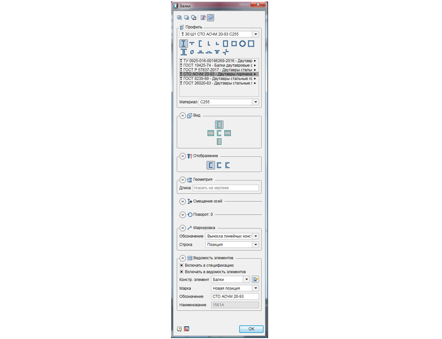
5.1. On the Metal Toolbar, we call the Beam command, then in the dialog window that appears, set the necessary parameters.

5.2. To begin with, in the upper part of the dialog you need to click on the Insert several icon, so that with several successive inserts into the drawing of this beam, its mark does not automatically change (the beam will be inserted with one mark).

5.3. In the dialog, set the necessary parameters for the beam:
- We choose a profile of an I-beam, of wide-shelf type according to the standard STO ASCM 20-93 and frame size 301. Material steel S255.
- View - from above.
- Display - "conditional".
- In the Geometry tab, leave unchanged (indicate on the drawing).
- The Offset Axis tab is left unchanged (the center of the section).
- The Rotate tab is left unchanged (“0” rotation).
- The Marking tab is left unchanged (callout of linear structures, position).
- In the Sheet Items tab, we tick Include in specification and Include in item list . The type of the structural element is left by default (beams).
5.4. Having set all the parameters, click OK and place the beams along the numerical axes.

5.5. Placing the beams, we complete the command by pressing the Esc key .
So, we have considered how the construction of the production building framework is carried out in nanoCAD SPDS Metal Structures.
In the next part we will analyze how to create vertical links, struts, runs and place them on the plan.
We invite you to take part in the free webinar "Creating a metal farm in nanoCAD SPDS Metal".
The purpose of the webinar is to demonstrate to CAD users how the efficiency of the work of design engineers is increased when using specialized software nanoCAD DPS Metal structures. The participants of the webinar will get acquainted with the updated functionality of the program, will see two-way automatic communication between the project manager, the drawing and the specification. In the framework of the webinar, the tools of the nanoCAD software program, Metal Structures, which allow to design various elements of metal structures, will be considered. An example will be shown of how to use a parametric object to quickly design a truss metal truss and automatically generate a list of elements and a specification for rolled metal.
 Dmitry Gostev, Leading Engineer, Magma Computer
Source: https://habr.com/ru/post/447836/
All Articles