Import 3D-models in Unity and pitfalls
We present the third article in our series on working with 3D models in Unity. Previous articles: “Features of working with Mesh in Unity” and “Unity: procedural editing of Mesh” .
In the world of computer graphics, there are many formats for representing 3D models. Some of them are positioned as universal, others as optimized for specific tasks or platforms. In any field they dream of working with a universal format, but reality tells us "no." Moreover, because of such a zoo, there is a vicious circle: the developers of “universal” tools invent their own internal formats to summarize the previous ones, increasing the population and producing means of format conversion. So there is a problem of data loss or corruption during conversion. The problem is as old as the world (IT world, of course), and it has not bypassed the import of models in Unity .
In this article we will talk about some of the difficulties that we have to deal with when working with models in Unity (features of the ModelImporter functioning, the difference in representations of 3D objects, etc.), as well as what tools we have created to overcome these difficulties.
')

Recall that for the API of video cards the minimal and only three-dimensional primitive is a triangle, while the geometry in FBX , for example, can be represented as quadrangles. Modern 3D-packages for creating models, as a rule, allow different levels of abstraction, but even there the result is rendered by means of triangles.
However, many tools are sharpened to work with quadrilaterals, which pushes 3D artists to use this primitive as the main one. In such cases, it is often required in TK to triangulate the model before implementation. If the triangulation is not done, the corresponding Unity module in standard mode automatically executes it when a file is added. Because of this, errors appear because the triangulation algorithms in different packages are implemented differently. When choosing a diagonal to divide a quadrilateral, ambiguity arises, hence most of the problems that can be divided into two groups.
The first is related to the correctness of the display of the model form. So, the shape of a non-planar quadrilateral directly depends on the choice of the diagonal.

Susanna triangulated in Blender (Quad Method: Beauty) and Unity (automatically upon import)
In addition, the baking algorithm for the normal map uses split data, which is why the difference in triangulation can generate artifacts in the form of a cross on a highlight.

Healthy man scooter and smoker scooter
Problems of the second group are found in the texture scan. For example, we have a quadrangle with a sufficiently blunt angle to cause an error. When previewed in a 3D package, it is broken by one of the diagonals into two completely folding triangles.
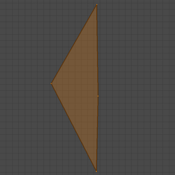
Source polygon

Blender Triangulated Ground
However, after importing into a project, it is found that this quadrilateral is broken by another diagonal and that one of the triangles is either generally degenerate or close to that.

Polygon in Unity with a triangle close to degenerate (the right triangle is almost indistinguishable from the segment)
The cause of the problems associated with the degeneracy of polygons are errors in floating-point calculations, as well as features of pixel interpolation during rendering. With such triangles, what the hell is happening: they jerk, each frame changes color. The extremely small size of the cross section creates difficulties in processing light, because of which parts of dynamic objects may flicker. And there is nothing good in the non-determinism of baking the lighting card .

In 3D modeling, there is often a difference between the actual number of vertices and their number in the 3D package. The essence of the problem lies in the information that is required for processing by the video card. The data structure for the vertex is predetermined and includes the position, normal, tangent, texture scan coordinates for each channel and color. That is, the two normals cannot be pushed into one vertex.
For some artists, it is not always obvious that the top is determined not only by its position. Modellers are well aware of the concepts of Hard / Soft Edges and UV Seams , but not everyone is aware of how they are implemented programmatically. Additionally confusing are 3D packages, which in standard mode show the number of vertices as the number of unique positions.
So, the usual Cube primitive is geometrically represented by 8 vertices. However, in order to correctly transfer the reflection of light from each face and correctly impose a texture, in each corner of the cube it is necessary to have 3 vertices with the same position, but different normals and texture coordinates, since in each of the corners 3 edges converge. A small block of documentation was devoted to this moment. There you can see examples.

Blender Cube Metrics

Cube Metrics in Unity
Faced with these and similar problems, we decided to create a tool for analyzing and validating models when importing into a Unity project. In other words, a custom validator that answers the query “Eat!” Will respond: “I will not! Rework, ”or spit out sets of warnings and values of various parameters, notifying you that something is not tasty.
For analysis and verification, we developed the following functionality:
What does this give us?
Calculations of the number of unique vertex positions, Hard Edges, UV Seams and colored vertices are necessary to check the conformity of the model conceived by the artist with the one that was imported into Unity . This functionality also allows you to monitor compliance with the requirements for optimizing the model (for example, so that the number of vertices does not exceed a certain value). Due to the same feature of 3D packages that actually show the number of unique positions, there are cases when the metric of the number of vertices in the model editor satisfies this restriction, but after adding a file to the project it may turn out that this is not the case.
Calculating the AABB and its center allows you to determine the offset of the model relative to the beginning of its own coordinate system. This is necessary for the predictable positioning of assets, which are initialized in the scene already while the application is running. Thus, the AABB building should have minY = 0 in an amicable way, and some chandeliers that are attached to the ceiling should have maxY = 0.


The output coordinates of the UV-sweep to the range of 0.0–1.0 - in most cases (for example, if the texture should be hidden on the model) is provided. Often, this approach is used to represent in the scene a multitude of low-detailed small objects (vegetation) and / or located in the distance, as well as tiling large homogeneous objects (buildings). In the case of tiling, the coordinate values of a specific UV channel are simply cut off the integer part at the shader level, if the Wrap Mode texture is set to Repeat .
Imagine now that you put the texture in the atlas (and covered with a blanket: 3). Already transformed coordinates corresponding to the atlas (x * scale + offset) will come to the shader. This time, most likely, there will be no whole part and there will be nothing to trim, and the model will crawl onto someone else’s texture (the blanket turned out to be small). This problem is solved in two ways.
The first one assumes that you pre-cut the whole part of the coordinates of the sweep. In this case, there is the likelihood of polygons overlapping, which we will discuss below.
The second is based on the fact that tiling textures are inherently an optimization method. Nobody forbids you to increase the size and sample the desired piece on the entire model. However, in this way the usable space of the atlas will be used inefficiently.

Texture overlays are also more often not random: they are needed to effectively use texture areas. It happens that a novice makes a mistake, the older comrade sees it, says a strong mot and a novice does not do that anymore. But it happens that the imposition of so small and is in such an unexpected place that the older comrade can not notice.
In an experienced team, the errors that were not noticed on the base sweep get into the project a bit more often than never. Another thing, when changing the conditions for the use of ready-made content.
Example. We worked with a set of models for dynamic objects in the game. Since there was no task to bake light for them, overlapping was allowed in the UV scan.
An example of basic UV scanning with overlays (shown in red)
But then we decided not to use these models as dynamic ones, but to arrange them as a static decor on the level. To optimize, as you know, the lighting of static objects in the scene is baked in a special atlas. These models did not have a separate UV2 channel for the lighting map , and the quality of the automatic generator operation in Unity did not suit us, so we decided to use the basic texture scan for baking as often as possible.
There were obvious problems with correct lighting. It is obvious that the rays that fall into some of the statue in the eye, should not create glareat the fifth point on the back of the head.
Incorrectly baked model lighting (left) and corrected (right)
Unity, when forming the lighting map , first of all tries to use the UV2 channel. If it is empty, then the main UV is used , if this one is empty, then excuse me, here you are an exception. There are two ways to bake models in a lighting map without pre-prepared UV2 in Unity .
As a first, Unity offers automatic generation of UV2 based on model geometry. This is faster than doing it manually; moreover, this tool can be configured using several parameters. But even despite this, the final imposition of light and shade is often unsatisfactory for highly detailed objects due to seams and wicking in the wrong places, besides the packaging of parts of such a scan is not the most effective.

The second way is to use the basic UV scan for baking. A very attractive option, because when working with one texture scan, there is less chance of making a mistake than working with two. For this reason, we try to minimize the number of models, in the base UV of which there are overlaps. The created toolkit helps us to do this.
Checking the texture scan for the sufficiency of a given pixel indent at a given texture resolution is more accurate UV validation based on rasterization. More about this method will be discussed in the next article in the series.
Summarize. Of course, it is almost impossible to track all the nuances: sometimes you have to put up with the imperfection of the result in order to complete the task on time. However, the identification of even some of these shortcomings allows you to speed up the development of the project and improve its quality.
In the world of computer graphics, there are many formats for representing 3D models. Some of them are positioned as universal, others as optimized for specific tasks or platforms. In any field they dream of working with a universal format, but reality tells us "no." Moreover, because of such a zoo, there is a vicious circle: the developers of “universal” tools invent their own internal formats to summarize the previous ones, increasing the population and producing means of format conversion. So there is a problem of data loss or corruption during conversion. The problem is as old as the world (IT world, of course), and it has not bypassed the import of models in Unity .
In this article we will talk about some of the difficulties that we have to deal with when working with models in Unity (features of the ModelImporter functioning, the difference in representations of 3D objects, etc.), as well as what tools we have created to overcome these difficulties.
')
Features of the ModelImporter
Recall that for the API of video cards the minimal and only three-dimensional primitive is a triangle, while the geometry in FBX , for example, can be represented as quadrangles. Modern 3D-packages for creating models, as a rule, allow different levels of abstraction, but even there the result is rendered by means of triangles.
However, many tools are sharpened to work with quadrilaterals, which pushes 3D artists to use this primitive as the main one. In such cases, it is often required in TK to triangulate the model before implementation. If the triangulation is not done, the corresponding Unity module in standard mode automatically executes it when a file is added. Because of this, errors appear because the triangulation algorithms in different packages are implemented differently. When choosing a diagonal to divide a quadrilateral, ambiguity arises, hence most of the problems that can be divided into two groups.
The first is related to the correctness of the display of the model form. So, the shape of a non-planar quadrilateral directly depends on the choice of the diagonal.
Susanna triangulated in Blender (Quad Method: Beauty) and Unity (automatically upon import)
In addition, the baking algorithm for the normal map uses split data, which is why the difference in triangulation can generate artifacts in the form of a cross on a highlight.
Healthy man scooter and smoker scooter
Problems of the second group are found in the texture scan. For example, we have a quadrangle with a sufficiently blunt angle to cause an error. When previewed in a 3D package, it is broken by one of the diagonals into two completely folding triangles.
Source polygon
Blender Triangulated Ground
However, after importing into a project, it is found that this quadrilateral is broken by another diagonal and that one of the triangles is either generally degenerate or close to that.
Polygon in Unity with a triangle close to degenerate (the right triangle is almost indistinguishable from the segment)
The cause of the problems associated with the degeneracy of polygons are errors in floating-point calculations, as well as features of pixel interpolation during rendering. With such triangles, what the hell is happening: they jerk, each frame changes color. The extremely small size of the cross section creates difficulties in processing light, because of which parts of dynamic objects may flicker. And there is nothing good in the non-determinism of baking the lighting card .
I am a 3D package, I see it
In 3D modeling, there is often a difference between the actual number of vertices and their number in the 3D package. The essence of the problem lies in the information that is required for processing by the video card. The data structure for the vertex is predetermined and includes the position, normal, tangent, texture scan coordinates for each channel and color. That is, the two normals cannot be pushed into one vertex.
For some artists, it is not always obvious that the top is determined not only by its position. Modellers are well aware of the concepts of Hard / Soft Edges and UV Seams , but not everyone is aware of how they are implemented programmatically. Additionally confusing are 3D packages, which in standard mode show the number of vertices as the number of unique positions.
So, the usual Cube primitive is geometrically represented by 8 vertices. However, in order to correctly transfer the reflection of light from each face and correctly impose a texture, in each corner of the cube it is necessary to have 3 vertices with the same position, but different normals and texture coordinates, since in each of the corners 3 edges converge. A small block of documentation was devoted to this moment. There you can see examples.
Blender Cube Metrics
Cube Metrics in Unity
Enough tolerating this!
Faced with these and similar problems, we decided to create a tool for analyzing and validating models when importing into a Unity project. In other words, a custom validator that answers the query “Eat!” Will respond: “I will not! Rework, ”or spit out sets of warnings and values of various parameters, notifying you that something is not tasty.
For analysis and verification, we developed the following functionality:
- counting the number of unique positions of vertices, colored vertices, Hard Edges , UV Seams ;
- calculation of Axis-Aligned Bounding Box (AABB) and its center;
- determination of the output of UV- scan coordinates for the range of 0.0–1.0;
- definition of texture overlays;
- checking the texture scan for the sufficiency of the specified pixel indentation at the specified texture resolution.
What does this give us?
Calculations of the number of unique vertex positions, Hard Edges, UV Seams and colored vertices are necessary to check the conformity of the model conceived by the artist with the one that was imported into Unity . This functionality also allows you to monitor compliance with the requirements for optimizing the model (for example, so that the number of vertices does not exceed a certain value). Due to the same feature of 3D packages that actually show the number of unique positions, there are cases when the metric of the number of vertices in the model editor satisfies this restriction, but after adding a file to the project it may turn out that this is not the case.
Calculating the AABB and its center allows you to determine the offset of the model relative to the beginning of its own coordinate system. This is necessary for the predictable positioning of assets, which are initialized in the scene already while the application is running. Thus, the AABB building should have minY = 0 in an amicable way, and some chandeliers that are attached to the ceiling should have maxY = 0.
The output coordinates of the UV-sweep to the range of 0.0–1.0 - in most cases (for example, if the texture should be hidden on the model) is provided. Often, this approach is used to represent in the scene a multitude of low-detailed small objects (vegetation) and / or located in the distance, as well as tiling large homogeneous objects (buildings). In the case of tiling, the coordinate values of a specific UV channel are simply cut off the integer part at the shader level, if the Wrap Mode texture is set to Repeat .
Imagine now that you put the texture in the atlas (and covered with a blanket: 3). Already transformed coordinates corresponding to the atlas (x * scale + offset) will come to the shader. This time, most likely, there will be no whole part and there will be nothing to trim, and the model will crawl onto someone else’s texture (the blanket turned out to be small). This problem is solved in two ways.
The first one assumes that you pre-cut the whole part of the coordinates of the sweep. In this case, there is the likelihood of polygons overlapping, which we will discuss below.
The second is based on the fact that tiling textures are inherently an optimization method. Nobody forbids you to increase the size and sample the desired piece on the entire model. However, in this way the usable space of the atlas will be used inefficiently.
Texture overlays are also more often not random: they are needed to effectively use texture areas. It happens that a novice makes a mistake, the older comrade sees it, says a strong mot and a novice does not do that anymore. But it happens that the imposition of so small and is in such an unexpected place that the older comrade can not notice.
In an experienced team, the errors that were not noticed on the base sweep get into the project a bit more often than never. Another thing, when changing the conditions for the use of ready-made content.
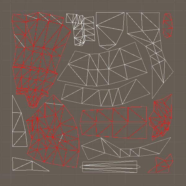
Example. We worked with a set of models for dynamic objects in the game. Since there was no task to bake light for them, overlapping was allowed in the UV scan.
An example of basic UV scanning with overlays (shown in red)
But then we decided not to use these models as dynamic ones, but to arrange them as a static decor on the level. To optimize, as you know, the lighting of static objects in the scene is baked in a special atlas. These models did not have a separate UV2 channel for the lighting map , and the quality of the automatic generator operation in Unity did not suit us, so we decided to use the basic texture scan for baking as often as possible.
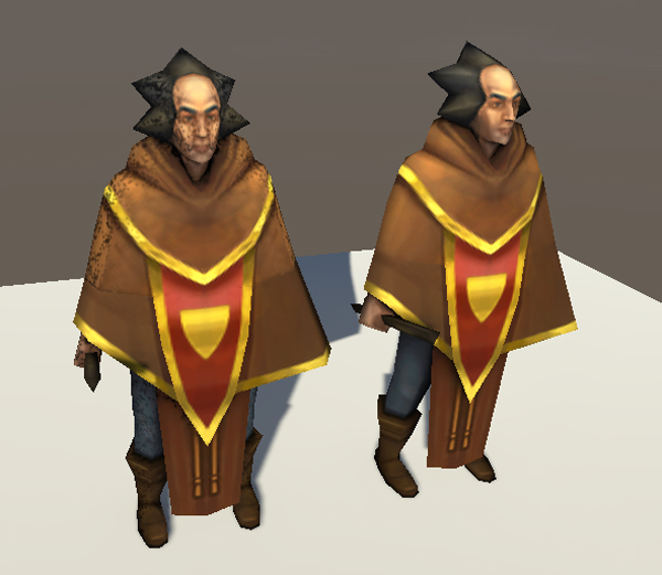
There were obvious problems with correct lighting. It is obvious that the rays that fall into some of the statue in the eye, should not create glare
Incorrectly baked model lighting (left) and corrected (right)
Unity, when forming the lighting map , first of all tries to use the UV2 channel. If it is empty, then the main UV is used , if this one is empty, then excuse me, here you are an exception. There are two ways to bake models in a lighting map without pre-prepared UV2 in Unity .
As a first, Unity offers automatic generation of UV2 based on model geometry. This is faster than doing it manually; moreover, this tool can be configured using several parameters. But even despite this, the final imposition of light and shade is often unsatisfactory for highly detailed objects due to seams and wicking in the wrong places, besides the packaging of parts of such a scan is not the most effective.
The second way is to use the basic UV scan for baking. A very attractive option, because when working with one texture scan, there is less chance of making a mistake than working with two. For this reason, we try to minimize the number of models, in the base UV of which there are overlaps. The created toolkit helps us to do this.
Checking the texture scan for the sufficiency of a given pixel indent at a given texture resolution is more accurate UV validation based on rasterization. More about this method will be discussed in the next article in the series.
Summarize. Of course, it is almost impossible to track all the nuances: sometimes you have to put up with the imperfection of the result in order to complete the task on time. However, the identification of even some of these shortcomings allows you to speed up the development of the project and improve its quality.
Source: https://habr.com/ru/post/447820/
All Articles