Climbing Elbrus - Reconnaissance. Technical Part 1. Registers, stacks and other technical details
 As promised , we continue to talk about the development of Elbrus processors . This article is technical. The information given in the article is not official documentation, because it was obtained from the study of Elbrus, much like a black box. But it will certainly be interesting for a better understanding of the architecture of Elbrus, because although we had official documentation, many of the details became clear only after lengthy experiments, when Embox did work.
Recall that in the previous article we talked about the basic system load and the serial port driver. Embox started, but for further progress, interrupts, a system timer were needed, and, of course, I would like to enable some set of unit tests, and for this we need setjmp. This article will focus on the registers, stacks, and other technical details necessary to implement all of these things.
We begin with a brief introduction to the architecture, which is the minimum information necessary to understand what will be discussed further. In the future, we will refer to information from this section.
Brief Introduction: Stacks
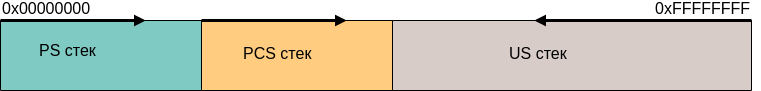
There are three stacks in Elbrus:
')
- Procedure Stack (PS)
- Link Stack (Procedure Chain Stack - PCS)
- User Stack - US
Let us examine them in more detail. The addresses in the figure are conditional; they show which direction the movement is going - from a larger address to a smaller one or vice versa.
The procedure stack (PS) is intended for data submitted to “operational” registers.
For example, it can be function arguments, in “normal” architectures this concept most closely corresponds to general-purpose registers. In contrast to “normal” processor architectures, the E2K registers used in functions are stacked on a separate stack.
The stack of binding information (PCS) is designed to accommodate information about the previous (caller) procedure and used during the return. Data on the return address, as well as in the case of registers, fit into a separate place. Therefore, stack promotion (for example, to exit by exception in C ++) is a more laborious process than in “normal” architectures. On the other hand, this eliminates stack overflow problems.
Both of these stacks (PS and PCS) are characterized by a base address, size, and current offset. These parameters are set in the PSP and PCSP registers, they are 128-bit and in assembler you need to refer to specific fields (for example, high or low). In addition, the operation of the stacks is closely related to the concept of the register file, more on this below. Interaction with the file occurs through the mechanism of pumping / paging registers. In this mechanism, the so-called “hardware pointer to the top of the stack” of the procedural or binding information plays an active role, respectively. This is also below. It is important that at each moment of time the data of these stacks are either in the RAM or in the register file.
It is also worth noting that these stacks (procedural stack and stack of binding information) grow upwards . We encountered this when implementing context_switch.
The user stack is also specified by the base address and size. The current index is in the USD.lo register. At its core, this is a classic stack that grows down. Only in contrast to “ordinary” architectures, information from other stacks does not fit there (registers and return addresses).
One non-standard, in my opinion, requirement for the boundaries and sizes of stacks is alignment by 4K, with what should be aligned on 4Kb with both the base address of the stack and its size. In other architectures, I have not seen such a restriction. We encountered this detail again when implementing context_switch.
Brief introduction: Registers. Register files. Register windows
Now that we have dealt with the stacks a bit, we need to understand how the information is presented in them. To do this, we need to introduce some more concepts.
Register file (RF) is a set of all registers. There are two register files that we need: one binding information file (chain file - CF), the other one is called a register file (RF), it stores “operational” registers that are stored on the procedural stack.
The register window is the region (set of registers) of the register file that is currently available.
I will explain in more detail. What is a set of registers, I think, no one needs to explain.
It is well known that one of the bottlenecks in the x86 architecture is just a small number of registers. In RISC-architectures with registers easier, usually about 16 registers, of which several (2-3) are used for official needs. Why not just make 128 registers, because it would seem that it will increase system performance? The answer is quite simple: in the processor instruction, you need a place to store the register address, and if there are a lot of them, a bit is also needed for it. Therefore, they go to all sorts of tricks, they make shadow registers, register banks, windows and so on. By shadow registers, I mean the principle of register organization in ARM. If an interruption or other situation occurs, then another set of registers is available with the same names (numbers), while the information stored in the original set remains there. Register banks, in fact, are very similar to shadow registers, there is simply no hardware switching of register sets and the programmer chooses which bank (set of registers) to access now.
Register windows are designed to optimize work with the stack. As you probably understand, in a “normal” architecture you enter a procedure, save registers onto a stack (or the calling procedure saves depends on agreements) and you can use registers, because the information is already stored on the stack. But access to memory is slow, and therefore must be avoided. Let us at the time of entering the procedure just make a new set of registers available, the data on the old one will be saved, and that means they do not need to be dropped into memory. In this case, when you return back to the calling procedure, the previous register window will also return, therefore all the data on the registers will be relevant. This is the concept of a register window.
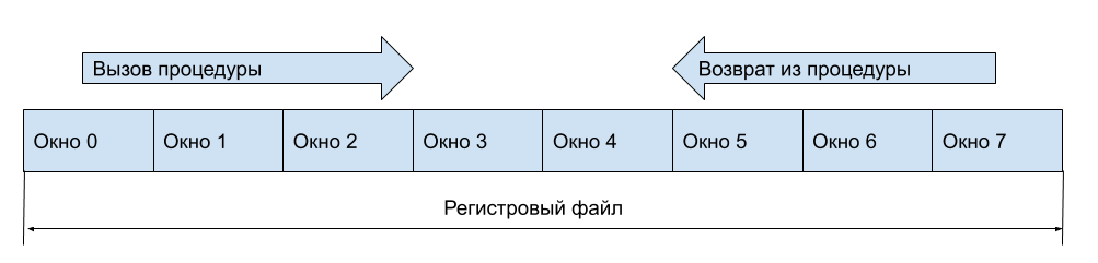
It is clear that it is still necessary to keep registers on the stack (in memory), but this can be done when the free register windows have run out.
And what to do with input and output registers (arguments at the entrance to the function and the return result)? Let's window will contain part of the registers visible from the previous window, more precisely, part of the registers will be available for both windows. Then in general, when you call a function, you do not have to access memory. Suppose our registers look like this
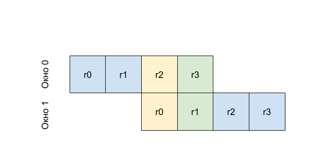
That is, r0 in the first window will be the same register as r2 at zero, and r1 from the first window will be the same register as r3. That is, by writing to r2 before calling the procedure (changing the window number), we get the value at r0 in the called procedure. This principle is called the rotating window mechanism.
Let's optimize a little more, because the creators of Elbrus did just that. Let's have a window, we will not have a fixed size, and variable, the window size can be set at the moment of entering the procedure. Do the same with the number of rotated registers. This of course will lead us to some problems, because if in classic rotated windows, there is an index of the window, through which it is determined that you need to save data from the register file to the stack or load it. But if you enter not the window index, but the index of the register with which our current window begins, this problem will not arise. In Elbrus, these indices are contained in the registers PSHTP (for the PS procedure stack) and PCSHTP (for the PCS procedure information stack). The documentation refers to as “hardware pointers to the top of the stack.” Now you can once again try to re-read about the stacks, I think it will be more clear.
As you understand, this mechanism implies that you have the ability to control what is in memory. That is, synchronize the register file and the stack. I mean the system programmer. If you are an application programmer, then the equipment will provide transparent input and output from the procedure. That is, if when you try to select a new window, the registers are not enough, then the register window will automatically “roll out”. In this case, all data from the register file will be saved to the corresponding stack (in memory), and the “pointer to the hardware top of the stack” (offset index) will be reset to zero. Similarly, the swap of the register file from the stack occurs automatically. But if you are developing, for example, context switching, which we actually did, then you need a mechanism for working with the hidden part of the register file. In Elbrus, the FLUSHR and FLUSHC commands are used for this. FLUSHR - cleaning the register file, all windows except the current one are dropped onto the procedural stack, the PSHTP index is reset to zero. FLUSHC - clears the link information file, everything except the current window is reset to the link information stack, the PCSHTP index is also reset to zero.
Brief Introduction: Implementation in Elbrus
Now that we have discussed non-obvious work with registers and stacks, let's talk more specifically about the different situations in Elbrus.
When we enter the next function, the processor creates two windows: a window in the PS stack and a window in the PCS stack.
A window in the PCS stack contains information necessary to return from a function: for example, IP (Instruction Pointer) of the instruction where it will be necessary to return from the function. With this, everything is more or less clear.
The window in the PS stack is somewhat trickier. The concept of the registers of the current window is introduced. In this window, you have access to the registers of the current window -% dr0,% dr1, ...,% dr15, ... That is, for us, as a user, they are always numbered from 0, but this is numbered relative to the base address of the current window. Through these registers, the arguments are passed when the function is called, and the value is returned, and used as general purpose registers within the function. Actually, this was explained when considering the mechanism of rotating register windows.
The size of the register window in Elbrus can be controlled. This, as I said, is needed for optimization. For example, we will only need 4 registers in the function to pass arguments and some calculations, in this case the programmer (or compiler) decides how many registers to allocate for the function, and based on this sets the window size. The window size is set by the setwd operation:
setwd wsz=0x10 Sets the window size in terms of quad-registers (128-bit registers).
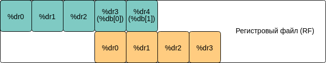
And now let's say you want to call a function from a function. For this, the concept of a rotated register window is already described. The picture above shows a fragment of the register file, where the function with window 1 (green) calls the function with window 2 (orange). In each of these two functions, you will have your own% dr0,% dr1, ... But the arguments will be transmitted through the so-called rotated registers. In other words, part of the registers of window 1 will become the registers of window 2 (note that these two windows overlap). These registers are also set by the window (see Rotating registers in the picture) and are addressed% db [0],% db [1], ... Thus, the register% dr0 in window 2 is nothing but the register% db [0] in window 1.
The window of rotated registers is set by the setbn operation:
setbn rbs = 0x3, rsz = 0x8 rbs sets the size of the window to be rotated, and rsz sets the base address, but relative to the current register window. Those. Here we have allocated 3 registers, starting from the 8th.
Based on the foregoing, let us show how the function call looks. For simplicity, we assume that the function takes one argument:
void my_func(uint64_t a) { } Then to call this function you need to prepare the window of rotated registers (we have already done this through setbn). Next, in the register% db0 put the value that will be passed to my_func. After that, you need to call the CALL instruction and do not forget to tell her where the rotating register window begins. We now skip the preparation for the call (the disp command), since it is not related to registers. As a result, the assembler call this function should look like this:
addd 0, %dr9, %db[0] disp %ctpr1, my_func call %ctpr1, wbs = 0x8 So, with the registers a bit sorted out. Now let's look at the stack of related information. It stores the so-called registers CR-s. In fact, two - CR0, CR1. And they already contain the necessary information to return from the function.

The CR0 and CR1 registers of the function window, which called the function with the registers marked in orange, are marked in green. The CR0 registers contain the Instruction Pointer function and a certain predicate file (PF-Predicate File), the story about it is beyond the scope of this article.
The CR1 registers contain data such as PSR (processor status word), window number, window size, and so on. In Elbrus, everything is so flexible that each procedure even saves information on CR1 whether floating point operation is included in the procedure and a register containing information about program exceptions, but of course you have to pay for this by saving additional information.
It is very important not to forget that the register file and the binding information file can be pumped out and pumped up from RAM and back (from the PS and PCS stacks described above). This point is important when implementing setjmp described below.
SETJMP / LONGJMP
And, finally, having somehow understood how the stacks and registers are arranged in Elbrus, you can start something useful, that is, add a new functionality to Embox.
In Embox, unit-testing requires setjmp / longjmp, so we had to implement these functions.
For implementation, you need to save / restore the registers: CR0, CR1, PSP, PCSP, USD, - already familiar to us from a brief introduction. In essence, saving / restoring is implemented in the forehead, but there is a significant nuance that is often hinted at in the description of the stacks and registers, namely: the stacks must be synchronized, because they are located not only in memory, but also in the register file. This nuance means that you need to take care of several features, without which nothing will work.
The first feature is to disable interrupts at times of save and restore. When restoring interrupts, it is necessary to prohibit, otherwise a situation may arise in which we enter the interrupt handler with half-switched stacks (meaning pumping the swap of register files described in the “short description”). And while saving, the problem is that after entering and exiting the interrupt, the processor can again pump up a part of the register file from the RAM (and this will spoil the PSHTP = 0 and PSHTP = 0 invariant conditions, just about them below). Actually, therefore, in both setjmp and longjmp, interrupts must be disabled. Here it is also necessary to note that experts from the MCST have advised us to use atomic brackets instead of disabling interrupts, but for now we are using the simplest (understandable to us) implementation.
The second feature is associated with the paging / pumping of the register file from memory. It consists in the following. The register file has a limited size and therefore is often pumped to memory and back. Therefore, if we simply save the values of the PSP and PSHTP registers, then we will fix the value of the current pointer in the memory and in the register file. But as the register file changes, then at the time the context is restored, it will point to data that is already incorrect (not what we “saved”). In order to avoid this, you need to flush the entire register file into memory. Thus, when saving to setjmp, we have the PCSP.ind registers in memory and the PCSHTP.ind registers in the register window. It turns out that you need to save all the PSSP.ind + PCSHTP.ind registers. Below is the function that performs this operation:
/* First arg is PCSP, 2nd arg is PCSHTP * Returns new PCSP value with updated PCSP.ind */ .type update_pcsp_ind,@function $update_pcsp_ind: setwd wsz = 0x4, nfx = 0x0 /* Here and below, 10 is size of PCSHTP.ind. Here we * extend the sign of PCSHTP.ind */ shld %dr1, (64 - 10), %dr1 shrd %dr1, (64 - 10), %dr1 /* Finally, PCSP.ind += PCSHTP.ind */ addd %dr1, %dr0, %dr0 E2K_ASM_RETURN It is also necessary to clarify a small point in this code described in the comment, namely, it is necessary to programmatically expand the sign in the PCSHTP.ind index, because the index can be negative and is stored in an additional code. To do this, we first shift to (64-10) to the left (64-bit register), 10 bits to the field, and then back.
The same goes for the PSP (stack of procedures)
/* First arg is PSP, 2nd arg is PSHTP * Returns new PSP value with updated PSP.ind */ .type update_psp_ind,@function $update_psp_ind: setwd wsz = 0x4, nfx = 0x0 /* Here and below, 12 is size of PSHTP.ind. Here we * extend the sign of PSHTP.ind as stated in documentation */ shld %dr1, (64 - 12), %dr1 shrd %dr1, (64 - 12), %dr1 muld %dr1, 2, %dr1 /* Finally, PSP.ind += PSHTP.ind */ addd %dr1, %dr0, %dr0 E2K_ASM_RETURN With a small difference (the field is 12 bits, and the registers are counted there in 128-bit terms, that is, the value needs to be multiplied by 2).
Setjmp code itself
C_ENTRY(setjmp): setwd wsz = 0x14, nfx = 0x0 /* It's for db[N] registers */ setbn rsz = 0x3, rbs = 0x10, rcur = 0x0 /* We must disable interrupts here */ disp %ctpr1, ipl_save ipd 3 call %ctpr1, wbs = 0x10 /* Store current IPL to dr9 */ addd 0, %db[0], %dr9 /* Store some registers to jmp_buf */ rrd %cr0.hi, %dr1 rrd %cr1.lo, %dr2 rrd %cr1.hi, %dr3 rrd %usd.lo, %dr4 rrd %usd.hi, %dr5 /* Prepare RF stack to flush in longjmp */ rrd %psp.hi, %dr6 rrd %pshtp, %dr7 addd 0, %dr6, %db[0] addd 0, %dr7, %db[1] disp %ctpr1, update_psp_ind ipd 3 call %ctpr1, wbs = 0x10 addd 0, %db[0], %dr6 /* Prepare CF stack to flush in longjmp */ rrd %pcsp.hi, %dr7 rrd %pcshtp, %dr8 addd 0, %dr7, %db[0] addd 0, %dr8, %db[1] disp %ctpr1, update_pcsp_ind ipd 3 call %ctpr1, wbs = 0x10 addd 0, %db[0], %dr7 std %dr1, [%dr0 + E2K_JMBBUFF_CR0_HI] std %dr2, [%dr0 + E2K_JMBBUFF_CR1_LO] std %dr3, [%dr0 + E2K_JMBBUFF_CR1_HI] std %dr4, [%dr0 + E2K_JMBBUFF_USD_LO] std %dr5, [%dr0 + E2K_JMBBUFF_USD_HI] std %dr6, [%dr0 + E2K_JMBBUFF_PSP_HI] std %dr7, [%dr0 + E2K_JMBBUFF_PCSP_HI] /* Enable interrupts */ addd 0, %dr9, %db[0] disp %ctpr1, ipl_restore ipd 3 call %ctpr1, wbs = 0x10 /* return 0 */ adds 0, 0, %r0 E2K_ASM_RETURN When implementing longjmp, it is important not to forget about the synchronization of both register files, therefore you need to flush not only the register window (flushr), but also the flush binding information file (flushc). We describe the macro:
#define E2K_ASM_FLUSH_CPU \ flushr; \ nop 2; \ flushc; \ nop 3; Now that all the information is in memory, we can safely restore registers to longjmp.
C_ENTRY(longjmp): setwd wsz = 0x14, nfx = 0x0 setbn rsz = 0x3, rbs = 0x10, rcur = 0x0 /* We must disable interrupts here */ disp %ctpr1, ipl_save ipd 3 call %ctpr1, wbs = 0x10 /* Store current IPL to dr9 */ addd 0, %db[0], %dr9 /* We have to flush both RF and CF to memory because saved values * of P[C]SHTP can be not valid here. */ E2K_ASM_FLUSH_CPU /* Load registers previously saved in setjmp. */ ldd [%dr0 + E2K_JMBBUFF_CR0_HI], %dr2 ldd [%dr0 + E2K_JMBBUFF_CR1_LO], %dr3 ldd [%dr0 + E2K_JMBBUFF_CR1_HI], %dr4 ldd [%dr0 + E2K_JMBBUFF_USD_LO], %dr5 ldd [%dr0 + E2K_JMBBUFF_USD_HI], %dr6 ldd [%dr0 + E2K_JMBBUFF_PSP_HI], %dr7 ldd [%dr0 + E2K_JMBBUFF_PCSP_HI], %dr8 rwd %dr2, %cr0.hi rwd %dr3, %cr1.lo rwd %dr4, %cr1.hi rwd %dr5, %usd.lo rwd %dr6, %usd.hi rwd %dr7, %psp.hi rwd %dr8, %pcsp.hi /* Enable interrupts */ addd 0, %dr9, %db[0] disp %ctpr1, ipl_restore ipd 3 call %ctpr1, wbs = 0x10 /* Actually, we return to setjmp caller with second * argument of longjmp stored on r1 register. */ adds 0, %r1, %r0 E2K_ASM_RETURN Context switch switching (context switch)
After we dealt with setjmp / longjmp, the basic implementation of context_switch seemed to us quite understandable. After all, as in the first case, we need to save / restore the binding information registers and stacks, plus we need to correctly restore the processor status register (UPSR).
I will explain. As in the case of setjmp, when saving registers, you first need to reset the register file and the binding information file into memory (flushr + flushc). After that, we need to save the current values of the CR0 and CR1 registers in order to jump back to exactly where the current flow was switched from when returning. Next, save the PS, PCS, and US stack descriptors. And finally, it is necessary to take care of the proper restoration of the interrupt mode - for these purposes we also save the UPSR register.
Assembler context_switch code:
C_ENTRY(context_switch): setwd wsz = 0x10, nfx = 0x0 /* Save prev UPSR */ rrd %upsr, %dr2 std %dr2, [%dr0 + E2K_CTX_UPSR] /* Disable interrupts before saving/restoring context */ rrd %upsr, %dr2 andnd %dr2, (UPSR_IE | UPSR_NMIE), %dr2 rwd %dr2, %upsr E2K_ASM_FLUSH_CPU /* Save prev CRs */ rrd %cr0.lo, %dr2 rrd %cr0.hi, %dr3 rrd %cr1.lo, %dr4 rrd %cr1.hi, %dr5 std %dr2, [%dr0 + E2K_CTX_CR0_LO] std %dr3, [%dr0 + E2K_CTX_CR0_HI] std %dr4, [%dr0 + E2K_CTX_CR1_LO] std %dr5, [%dr0 + E2K_CTX_CR1_HI] /* Save prev stacks */ rrd %usd.lo, %dr3 rrd %usd.hi, %dr4 rrd %psp.lo, %dr5 rrd %psp.hi, %dr6 rrd %pcsp.lo, %dr7 rrd %pcsp.hi, %dr8 std %dr3, [%dr0 + E2K_CTX_USD_LO] std %dr4, [%dr0 + E2K_CTX_USD_HI] std %dr5, [%dr0 + E2K_CTX_PSP_LO] std %dr6, [%dr0 + E2K_CTX_PSP_HI] std %dr7, [%dr0 + E2K_CTX_PCSP_LO] std %dr8, [%dr0 + E2K_CTX_PCSP_HI] /* Load next CRs */ ldd [%dr1 + E2K_CTX_CR0_LO], %dr2 ldd [%dr1 + E2K_CTX_CR0_HI], %dr3 ldd [%dr1 + E2K_CTX_CR1_LO], %dr4 ldd [%dr1 + E2K_CTX_CR1_HI], %dr5 rwd %dr2, %cr0.lo rwd %dr3, %cr0.hi rwd %dr4, %cr1.lo rwd %dr5, %cr1.hi /* Load next stacks */ ldd [%dr1 + E2K_CTX_USD_LO], %dr3 ldd [%dr1 + E2K_CTX_USD_HI], %dr4 ldd [%dr1 + E2K_CTX_PSP_LO], %dr5 ldd [%dr1 + E2K_CTX_PSP_HI], %dr6 ldd [%dr1 + E2K_CTX_PCSP_LO], %dr7 ldd [%dr1 + E2K_CTX_PCSP_HI], %dr8 rwd %dr3, %usd.lo rwd %dr4, %usd.hi rwd %dr5, %psp.lo rwd %dr6, %psp.hi rwd %dr7, %pcsp.lo rwd %dr8, %pcsp.hi /* Restore next UPSR */ ldd [%dr1 + E2K_CTX_UPSR], %dr2 rwd %dr2, %upsr E2K_ASM_RETURN Another important point is the initialization of the OS thread. In Embox, each thread has a certain primary procedure.
void _NORETURN thread_trampoline(void); In which all further work of a flow will be executed. Thus, we need to somehow prepare the stacks to call this function, it is here that we are faced with the fact that there are three stacks, and they are not growing in the same direction. According to the architecture, the flow is created with a single stack, more precisely, it is a single place for the stack, at the top we have a structure that describes the flow itself, and so on, here we had to take care of different stacks, do not forget that they should be aligned 4 KB, do not forget any access rights and so on.
As a result, at the moment we decided that we will divide the space under the stack into three parts, a quarter under the stack of binding information, a quarter under the procedural stack and half under the user stack.
I cite the code in order to be able to estimate how big it is, you need to take into account that this is minimal initialization.
/* This value is used for both stack base and size align. */ #define E2K_STACK_ALIGN (1UL << 12) #define round_down(x, bound) ((x) & ~((bound) - 1)) /* Reserve 1/4 for PSP stack, 1/4 for PCSP stack, and 1/2 for USD stack */ #define PSP_CALC_STACK_BASE(sp, size) binalign_bound(sp - size, E2K_STACK_ALIGN) #define PSP_CALC_STACK_SIZE(sp, size) binalign_bound((size) / 4, E2K_STACK_ALIGN) #define PCSP_CALC_STACK_BASE(sp, size) \ (PSP_CALC_STACK_BASE(sp, size) + PSP_CALC_STACK_SIZE(sp, size)) #define PCSP_CALC_STACK_SIZE(sp, size) binalign_bound((size) / 4, E2K_STACK_ALIGN) #define USD_CALC_STACK_BASE(sp, size) round_down(sp, E2K_STACK_ALIGN) #define USD_CALC_STACK_SIZE(sp, size) \ round_down(USD_CALC_STACK_BASE(sp, size) - PCSP_CALC_STACK_BASE(sp, size),\ E2K_STACK_ALIGN) static void e2k_calculate_stacks(struct context *ctx, uint64_t sp, uint64_t size) { uint64_t psp_size, pcsp_size, usd_size; log_debug("Stacks:\n"); ctx->psp_lo |= PSP_CALC_STACK_BASE(sp, size) << PSP_BASE; ctx->psp_lo |= E2_RWAR_RW_ENABLE << PSP_RW; psp_size = PSP_CALC_STACK_SIZE(sp, size); assert(psp_size); ctx->psp_hi |= psp_size << PSP_SIZE; log_debug(" PSP.base=0x%lx, PSP.size=0x%lx\n", PSP_CALC_STACK_BASE(sp, size), psp_size); ctx->pcsp_lo |= PCSP_CALC_STACK_BASE(sp, size) << PCSP_BASE; ctx->pcsp_lo |= E2_RWAR_RW_ENABLE << PCSP_RW; pcsp_size = PCSP_CALC_STACK_SIZE(sp, size); assert(pcsp_size); ctx->pcsp_hi |= pcsp_size << PCSP_SIZE; log_debug(" PCSP.base=0x%lx, PCSP.size=0x%lx\n", PCSP_CALC_STACK_BASE(sp, size), pcsp_size); ctx->usd_lo |= USD_CALC_STACK_BASE(sp, size) << USD_BASE; usd_size = USD_CALC_STACK_SIZE(sp, size); assert(usd_size); ctx->usd_hi |= usd_size << USD_SIZE; log_debug(" USD.base=0x%lx, USD.size=0x%lx\n", USD_CALC_STACK_BASE(sp, size), usd_size); } static void e2k_calculate_crs(struct context *ctx, uint64_t routine_addr) { uint64_t usd_size = (ctx->usd_hi >> USD_SIZE) & USD_SIZE_MASK; /* Reserve space in hardware stacks for @routine_addr */ /* Remark: We do not update psp.hi to reserve space for arguments, * since routine do not accepts any arguments. */ ctx->pcsp_hi |= SZ_OF_CR0_CR1 << PCSP_IND; ctx->cr0_hi |= (routine_addr >> CR0_IP) << CR0_IP; ctx->cr1_lo |= PSR_ALL_IRQ_ENABLED << CR1_PSR; /* Divide on 16 because it field contains size in terms * of 128 bit values. */ ctx->cr1_hi |= (usd_size >> 4) << CR1_USSZ; } void context_init(struct context *ctx, unsigned int flags, void (*routine_fn)(void), void *sp, unsigned int stack_size) { memset(ctx, 0, sizeof(*ctx)); e2k_calculate_stacks(ctx, sp, stack_size); e2k_calculate_crs(ctx, (uint64_t) routine_fn); if (!(flags & CONTEXT_IRQDISABLE)) { ctx->upsr |= (UPSR_IE | UPSR_NMIE); } } The article also contained work with interruptions, exceptions and timers, but since it turned out to be so big, we decided to tell about it in the next part .
Just in case, I repeat, this material is not official documentation! For official support, documentation, and the rest, you need to contact the MCST directly. The code in Embox is naturally open, but in order to build it, you will need a cross-compiler, which, again, can be obtained from the MCST .
Source: https://habr.com/ru/post/447704/
All Articles